EP1522687B2 - Collecteur à couche d'air - Google Patents
Collecteur à couche d'air Download PDFInfo
- Publication number
- EP1522687B2 EP1522687B2 EP04018050.7A EP04018050A EP1522687B2 EP 1522687 B2 EP1522687 B2 EP 1522687B2 EP 04018050 A EP04018050 A EP 04018050A EP 1522687 B2 EP1522687 B2 EP 1522687B2
- Authority
- EP
- European Patent Office
- Prior art keywords
- shells
- another
- air
- accordance
- exhaust gas
- Prior art date
- Legal status (The legal status is an assumption and is not a legal conclusion. Google has not performed a legal analysis and makes no representation as to the accuracy of the status listed.)
- Expired - Lifetime
Links
Images

Classifications
-
- F—MECHANICAL ENGINEERING; LIGHTING; HEATING; WEAPONS; BLASTING
- F01—MACHINES OR ENGINES IN GENERAL; ENGINE PLANTS IN GENERAL; STEAM ENGINES
- F01N—GAS-FLOW SILENCERS OR EXHAUST APPARATUS FOR MACHINES OR ENGINES IN GENERAL; GAS-FLOW SILENCERS OR EXHAUST APPARATUS FOR INTERNAL-COMBUSTION ENGINES
- F01N13/00—Exhaust or silencing apparatus characterised by constructional features
- F01N13/08—Other arrangements or adaptations of exhaust conduits
- F01N13/10—Other arrangements or adaptations of exhaust conduits of exhaust manifolds
-
- F—MECHANICAL ENGINEERING; LIGHTING; HEATING; WEAPONS; BLASTING
- F01—MACHINES OR ENGINES IN GENERAL; ENGINE PLANTS IN GENERAL; STEAM ENGINES
- F01N—GAS-FLOW SILENCERS OR EXHAUST APPARATUS FOR MACHINES OR ENGINES IN GENERAL; GAS-FLOW SILENCERS OR EXHAUST APPARATUS FOR INTERNAL-COMBUSTION ENGINES
- F01N13/00—Exhaust or silencing apparatus characterised by constructional features
- F01N13/18—Construction facilitating manufacture, assembly, or disassembly
- F01N13/1888—Construction facilitating manufacture, assembly, or disassembly the housing of the assembly consisting of two or more parts, e.g. two half-shells
- F01N13/1894—Construction facilitating manufacture, assembly, or disassembly the housing of the assembly consisting of two or more parts, e.g. two half-shells the parts being assembled in longitudinal direction
-
- F—MECHANICAL ENGINEERING; LIGHTING; HEATING; WEAPONS; BLASTING
- F01—MACHINES OR ENGINES IN GENERAL; ENGINE PLANTS IN GENERAL; STEAM ENGINES
- F01N—GAS-FLOW SILENCERS OR EXHAUST APPARATUS FOR MACHINES OR ENGINES IN GENERAL; GAS-FLOW SILENCERS OR EXHAUST APPARATUS FOR INTERNAL-COMBUSTION ENGINES
- F01N13/00—Exhaust or silencing apparatus characterised by constructional features
- F01N13/08—Other arrangements or adaptations of exhaust conduits
- F01N13/10—Other arrangements or adaptations of exhaust conduits of exhaust manifolds
- F01N13/102—Other arrangements or adaptations of exhaust conduits of exhaust manifolds having thermal insulation
-
- F—MECHANICAL ENGINEERING; LIGHTING; HEATING; WEAPONS; BLASTING
- F01—MACHINES OR ENGINES IN GENERAL; ENGINE PLANTS IN GENERAL; STEAM ENGINES
- F01N—GAS-FLOW SILENCERS OR EXHAUST APPARATUS FOR MACHINES OR ENGINES IN GENERAL; GAS-FLOW SILENCERS OR EXHAUST APPARATUS FOR INTERNAL-COMBUSTION ENGINES
- F01N13/00—Exhaust or silencing apparatus characterised by constructional features
- F01N13/18—Construction facilitating manufacture, assembly, or disassembly
- F01N13/1872—Construction facilitating manufacture, assembly, or disassembly the assembly using stamp-formed parts or otherwise deformed sheet-metal
-
- F—MECHANICAL ENGINEERING; LIGHTING; HEATING; WEAPONS; BLASTING
- F01—MACHINES OR ENGINES IN GENERAL; ENGINE PLANTS IN GENERAL; STEAM ENGINES
- F01N—GAS-FLOW SILENCERS OR EXHAUST APPARATUS FOR MACHINES OR ENGINES IN GENERAL; GAS-FLOW SILENCERS OR EXHAUST APPARATUS FOR INTERNAL-COMBUSTION ENGINES
- F01N2450/00—Methods or apparatus for fitting, inserting or repairing different elements
- F01N2450/22—Methods or apparatus for fitting, inserting or repairing different elements by welding or brazing
-
- F—MECHANICAL ENGINEERING; LIGHTING; HEATING; WEAPONS; BLASTING
- F01—MACHINES OR ENGINES IN GENERAL; ENGINE PLANTS IN GENERAL; STEAM ENGINES
- F01N—GAS-FLOW SILENCERS OR EXHAUST APPARATUS FOR MACHINES OR ENGINES IN GENERAL; GAS-FLOW SILENCERS OR EXHAUST APPARATUS FOR INTERNAL-COMBUSTION ENGINES
- F01N2470/00—Structure or shape of exhaust gas passages, pipes or tubes
- F01N2470/24—Concentric tubes or tubes being concentric to housing, e.g. telescopically assembled
-
- F—MECHANICAL ENGINEERING; LIGHTING; HEATING; WEAPONS; BLASTING
- F01—MACHINES OR ENGINES IN GENERAL; ENGINE PLANTS IN GENERAL; STEAM ENGINES
- F01N—GAS-FLOW SILENCERS OR EXHAUST APPARATUS FOR MACHINES OR ENGINES IN GENERAL; GAS-FLOW SILENCERS OR EXHAUST APPARATUS FOR INTERNAL-COMBUSTION ENGINES
- F01N2530/00—Selection of materials for tubes, chambers or housings
- F01N2530/02—Corrosion resistive metals
- F01N2530/04—Steel alloys, e.g. stainless steel
-
- F—MECHANICAL ENGINEERING; LIGHTING; HEATING; WEAPONS; BLASTING
- F02—COMBUSTION ENGINES; HOT-GAS OR COMBUSTION-PRODUCT ENGINE PLANTS
- F02B—INTERNAL-COMBUSTION PISTON ENGINES; COMBUSTION ENGINES IN GENERAL
- F02B37/00—Engines characterised by provision of pumps driven at least for part of the time by exhaust
Definitions
- the present invention relates to an air gap manifold for connecting exhaust gas outlet openings of an internal combustion engine, in particular motor vehicle engine, with an exhaust inlet opening of an exhaust system, with an inner part with a plurality of push-fit into each other exhaust ducts, a surrounding the inner part, gas-tight outer part and an existing between the inner part and outer part air gap.
- An example of such an air gap bend is in EP 0 582 985 A shown.
- the invention has for its object to provide an air gap bend of the type mentioned, on the one hand is low in the production and on the other hand allows compliance with the emissions regulations.
- the exhaust ducts of the inner part are at least partially formed by shells, which are connected to each other by common edge-side forming, in particular folding.
- the formation of the exhaust ducts of the inner part of shells is particularly inexpensive to manufacture.
- the shells can be pulled cheaply.
- Especially compared to welded joints results in a great cost advantage, especially when exhaust manifolds for turbocharger must be manufactured without welding spatter. Only expensive laser and TIG welding techniques can then be considered.
- the forming compound of the shells according to the invention is for a sweat-spatter and on the other hand with little effort feasible.
- the tightness of the forming connection between the shells is sufficient, since the outer shell of the manifold is absolutely gas-tight and therefore a small leakage of the inner part does not cause problems.
- the thickness of the inner part can be kept relatively low, since no minimum thickness is required for the forming connection of the shells other than welding.
- various types of steel for example, austenitic steel can be used.
- the shells of the inner part may be provided with beads.
- the shells of the outer part may have beads to increase the rigidity.
- the shells of the outer part are preferably welded together.
- the welded joints can be arranged on the outside, so that there is no risk of contamination of the interior of the exhaust manifold. It can also be used more cost-effective welding processes.
- the inner shells can be locked by individual welds against each other. Since only a few spot welds are required to reliably prevent displacement, simple spot welds can be used without undue cost increase.
- the shells can be embossed together.
- the outer part preferably consists of two half-shells.
- the exhaust passages of the inner part preferably each consist of two half-shells.
- a particularly advantageous use of the air gap bend according to the invention is given in internal combustion engines with a turbocharger, since the manifold according to the invention can be made particularly inexpensive welding spatter free.
- the preparation of the air-gap bend according to the invention is carried out such that first the one part of the exhaust ducts forming shells of the inner part are inserted into each other according to the desired sliding seat arrangement, then the respective other part of the exhaust ducts forming shells also, and then only the associated shells of the exhaust pipes together be joined together by pairs together edge formed, in particular folded.
- the individual exhaust ducts are not first composed of, for example, two shells and then inserted the exhaust ducts formed in one another, but the nesting is done separately for each half of the inner part, and only then are the two halves of all exhaust ducts of the inner part connected to each other simultaneously.
- the cross sections of the exhaust ducts in the sliding seat areas are adapted to each other.
- the shells of the respective exhaust ducts are locked if necessary by welding points against each other. Then, the inner part is inserted into the shells of the outer part and these are connected in a gas-tight manner by welding.
- the shells of the inner part are preferably made of sheet metal, in particular by deep drawing. Preferably beads are embossed in order to increase the rigidity of the shells.
- two half shells are manufactured per exhaust guide, which are then connected to each other simultaneously with the other half shells.
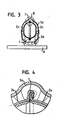
- the illustrated air gap manifold comprises an inner part 1 with a plurality of push-fit into each other inserted exhaust ducts 2, 3 and 4 and a surrounding the inner part 1 at a distance, gas-tight outer part 5. Between inner part 1 and outer part 5 is thereby formed an air gap 6, the heat insulation of Exhaust manifold causes.
- the exhaust ducts 2, 3 and 4 are each formed of two half shells 2a and 2b, 3a and 3b, 4a and 4b, which are connected to one another at the edge.
- the connection is a folded connection, as in Fig. 4 is shown.
- the edge of one half-shell 3a is bent around the edge of the other half-shell 3b.
- the exhaust ducts 2, 3 and 4 are, as I said, inserted into each other with sliding fit.
- a falzoker area 8 is formed, to which the associated end 3 ", 4" of each adjacent Exhaust guide 2, 3 and 4 is arranged with sliding seat.
- the other end 2 "of the exhaust gas guide 2 is connected in a gastight manner together with the outer shell 5 to a first inlet flange 9.
- a second inlet flange 10 is gas-tightly connected to the outer shell 5 and the end 11 'of a lateral branch 11 of the exhaust gas guide 3.
- Third and fourth inlet flanges 12, 13 are finally gas-tightly connected to the outer shell 5 and to a respective rigid sleeve 14, 14.
- the sleeve 14 is seated in a lateral branch 15 of the exhaust gas guide 4 and the sleeve 14 'is also fitted with a sliding fit in the second end 4' Exhaust system 4.
- the exhaust gas guide 4 has a second branch 16, in which a further sleeve 17 is inserted with sliding seat.
- This sleeve 17 is connected in a gastight manner with an outlet flange 18 together with the outer part 5.
- a continuing pipe of a conventional exhaust system can be connected. Accordingly, the inlet flanges 9, 10, 12 and 13 can be connected to exhaust gas outlet openings of an internal combustion engine.
- the outer part 5 also has two half shells 5a, 5b.
- the parting plane I of the half-shells 5a and 5b extends at an angle of approximately 90 ° to the parting plane II of the half-shells 2a, 2b, 3a, 3b, 4a and 4b of the inner part 1, and approximately parallel to the plane of the flanges 9, 10th , 12 and 13.
- the production of the illustrated air-gap bend essentially takes place in such a way that firstly all half-shells 2a, 2b, 3a, 3b, 4a and 4b of the inner part 1 and 5a and 5b of the outer part 5 are produced.
- beads 19 can be introduced into the half shells.
- each one half shells 2a, 3a and 4a of the inner part 1 are inserted into each other according to the desired sliding seat arrangement.
- the half-shells 2b, 3b and 4b of the inner part 1 are inserted into one another.
- the sleeves 14 and 14 ' the nested shells 2a, 3a and 4a and 2b, 3b and 4b are inserted into a forming tool.
- the inner part is finished and is used after removal from the forming tool in the lower shell 5b of the outer part 5. Together with this, the inner part 1 is then gas-tightly connected to the inlet flanges 9, 10, 12 and 13, in particular welded. Then, the sleeve 17 is welded gas-tight together with the upper shell 5a of the outer part 5 with the outlet flange 18. Subsequently, the upper shell 5a of the outer part 5 is placed on the lower shell 5b and welded gas-tight in the overlapping region.
- the two half-shells 5a, 5b of the outer part 5 can be connected to each other by normal welding methods, since the weld is on the outside.
- the illustrated and described embodiment of the inner part with sliding seats allows otherwise in a known manner a substantially unhindered thermal expansion of the exhaust ducts 2, 3 and 4 of the inner part 1, in particular a greater thermal expansion due to the greater heating of the inner part 1 relative to the outer part 5.
- the outer part on the other hand ensures a high gas-tightness of the air-gap bend. In this way, a well-fit air-gap manifold can be produced at a relatively low cost.
Landscapes
- Engineering & Computer Science (AREA)
- Chemical & Material Sciences (AREA)
- Combustion & Propulsion (AREA)
- Mechanical Engineering (AREA)
- General Engineering & Computer Science (AREA)
- Exhaust Silencers (AREA)
- Medicines That Contain Protein Lipid Enzymes And Other Medicines (AREA)
- Medicines Containing Material From Animals Or Micro-Organisms (AREA)
Claims (10)
- Collecteur à couche d'air pour la liaison d'ouvertures de sortie de gaz d'échappement d'un moteur à combustion, en particulier d'un moteur de véhicule automobile, comprenant une ouverture d'entrée de gaz d'échappement dans une installation de gaz d'échappement, comprenant une partie intérieure (1) formée au moins partiellement par des coques (2a, 2b, 3a, 3b, 4a, 4b), qui sont reliées les unes aux autres par déformation conjointe du côté de leur bordure, une partie extérieure (5) également constituée par des coques (5a, 5b), réalisée de manière étanche aux gaz et entourant la partie intérieure (1), et une couche d'air (6) prévue entre la partie intérieure (1) et la partie extérieure (5),
caractérisé en ce que la partie intérieure comprend plusieurs guidages de gaz d'échappement (2, 3, 4) enfichés en coulissement les uns dans les autres et formés par les coques (2a, 2b, 3a, 3b, 4a, 4b), et en ce que les coques (5a, 5b) qui forment la partie extérieure sont soudées les unes aux autres. - Collecteur à couche d'air selon la revendication 1,
caractérisé en ce que les coques (2a, 2b, 3a, 3b, 4a, 4b) de la partie intérieure (1) sont reliées les unes aux autres par pliage. - Collecteur à couche d'air selon la revendication 1 ou 2,
caractérisé en ce que les coques (2a, 2b, 3a, 3b, 4a, 4b) de la partie intérieure (1) et/ou les coques (5a, 5b) de la partie extérieure (5) sont en tôle et/ou présentent des moulures (19). - Collecteur à couche d'air selon la revendication 3,
caractérisé en ce que les coques (2a, 2b, 3a, 3b, 4a, 4b) de la partie intérieure sont verrouillées les unes par rapport aux autres, en particulier au moyen de points de soudure individuels. - Collecteur à couche d'air selon l'une des revendications précédentes,
caractérisé en ce que la partie extérieure (5) est constituée par deux demi-coques (5a, 5b). - Collecteur à couche d'air selon l'une des revendications précédentes,
caractérisé en ce que les coques (2a, 2b, 3a, 3b, 4a, 4b) de la partie intérieure (1) sont des demi-coques, telles que le plan de séparation (I) de la coque extérieure (5) et le plan de séparation (II) de la coque intérieure (1) sont de préférence approximativement à angle droit l'un par rapport à l'autre. - Collecteur à couche d'air selon l'une des revendications précédentes,
caractérisé par l'utilisation pour un moteur à combustion avec turbochargeur. - Procédé pour la réalisation d'un collecteur à couche d'air selon la revendication 1,
caractérisé en ce que l'on enfiche tout d'abord les unes dans les autres en correspondance de l'agencement souhaité à coulissement les coques (2a, 3a, 4a) qui forment respectivement une partie des guidages de gaz d'échappement (2, 3, 4) de la partie intérieure (1), en ce que l'on enfiche alors également les coques (2b, 3b, 4b) qui forment respectivement l'autre partie des guidages de gaz d'échappement (2, 3, 4), et en ce que les coques associées (2a, 2b, 3a, 3b, 4a, 4b) des guidages de gaz d'échappement (2, 3, 4) sont alors reliées conjointement les unes aux autres uniquement à ce moment, en les déformant conjointement par paires sur le côté de leur bordure, en particulier par pliage. - Procédé selon la revendication 8,
caractérisé en ce que les coques (2a, 2b, 3a, 3b, 4a, 4b) de la partie intérieure (1) sont verrouillées les unes par rapport aux autres par des points de soudure individuels, et/ou en ce que les coques (5a, 5b) de la partie extérieure (5) sont soudées les unes aux autres de manière étanche aux gaz. - Procédé selon la revendication 8 ou 9,
caractérisé en ce que les coques (2a, 2b, 3a, 3b, 4a, 4b) de la partie intérieure (1) et/ou les coques (5a, 5b) de la partie extérieure (5) sont réalisées en tôle et/ou sont pourvues de moulures.
Applications Claiming Priority (2)
| Application Number | Priority Date | Filing Date | Title |
|---|---|---|---|
| DE10346552A DE10346552A1 (de) | 2003-10-07 | 2003-10-07 | Luftspaltkrümmer |
| DE10346552 | 2003-10-07 |
Publications (4)
| Publication Number | Publication Date |
|---|---|
| EP1522687A2 EP1522687A2 (fr) | 2005-04-13 |
| EP1522687A3 EP1522687A3 (fr) | 2005-11-30 |
| EP1522687B1 EP1522687B1 (fr) | 2010-05-05 |
| EP1522687B2 true EP1522687B2 (fr) | 2014-09-24 |
Family
ID=34306307
Family Applications (1)
| Application Number | Title | Priority Date | Filing Date |
|---|---|---|---|
| EP04018050.7A Expired - Lifetime EP1522687B2 (fr) | 2003-10-07 | 2004-07-29 | Collecteur à couche d'air |
Country Status (6)
| Country | Link |
|---|---|
| US (1) | US20050072143A1 (fr) |
| EP (1) | EP1522687B2 (fr) |
| JP (1) | JP2005113910A (fr) |
| KR (1) | KR20050033843A (fr) |
| AT (1) | ATE467038T1 (fr) |
| DE (2) | DE10346552A1 (fr) |
Families Citing this family (18)
| Publication number | Priority date | Publication date | Assignee | Title |
|---|---|---|---|---|
| DE10360645A1 (de) * | 2003-12-23 | 2005-07-21 | Daimlerchrysler Ag | Auspuffkrümmer |
| WO2006035188A1 (fr) * | 2004-09-29 | 2006-04-06 | Renault S.A.S. | Collecteur d'echappement a double paroi |
| DE102005011639B4 (de) * | 2005-03-14 | 2015-10-22 | Faurecia Emissions Control Technologies, Germany Gmbh | Luftspaltisolierter Abgaskrümmer |
| WO2007081669A2 (fr) * | 2006-01-03 | 2007-07-19 | Metaldyne Company, Llc | Tubulure d'échappement à paroi double et procédé de fabrication de celle-ci |
| DE102007006699A1 (de) * | 2007-02-10 | 2008-08-14 | Bayerische Motoren Werke Aktiengesellschaft | Abgasanlage für eine Brennkraftmaschine |
| DE102007062660A1 (de) | 2007-12-24 | 2009-06-25 | J. Eberspächer GmbH & Co. KG | Abgaskrümmer |
| DE102007062661A1 (de) | 2007-12-24 | 2009-06-25 | J. Eberspächer GmbH & Co. KG | Abgassammler |
| DE102007062659A1 (de) | 2007-12-24 | 2009-06-25 | J. Eberspächer GmbH & Co. KG | Abgassammler und zugehöriges Herstellungsverfahren |
| DE102008047448B4 (de) * | 2008-09-16 | 2020-09-24 | Bayerische Motoren Werke Aktiengesellschaft | Abgasturbolader |
| US20100229540A1 (en) * | 2009-03-11 | 2010-09-16 | Indmar Products Company Inc. | Combination Liquid-Cooled Exhaust Manifold Assembly And Catalytic Converter Assembly For A Marine Engine |
| DE102010062049A1 (de) * | 2010-11-26 | 2012-05-31 | J. Eberspächer GmbH & Co. KG | Schalldämpfer |
| JP5848597B2 (ja) | 2011-12-21 | 2016-01-27 | インターナショナル・ビジネス・マシーンズ・コーポレーションInternational Business Machines Corporation | Cmdbを利用したソフトウェア構成値の最適化方法、装置、システムおよびプログラム |
| JP5849986B2 (ja) * | 2013-04-18 | 2016-02-03 | マツダ株式会社 | エンジンの触媒付き排気管構造 |
| DE102014103820A1 (de) * | 2014-03-20 | 2015-09-24 | Benteler Automobiltechnik Gmbh | Abgaskrümmer für eine Abgasanlage eines Verbrennungsmotors |
| US10151414B2 (en) | 2015-02-09 | 2018-12-11 | Dixon Valve & Coupling Company | Intake manifold |
| USD779559S1 (en) * | 2015-02-09 | 2017-02-21 | Dixon Valve & Coupling Company, Inc. | Intake manifold |
| DE112015006433T5 (de) | 2015-04-09 | 2017-12-28 | Cummins Inc. | Versteifungsrippen für Abgaskrümmer |
| DE102015116018A1 (de) * | 2015-09-22 | 2017-03-23 | Tenneco Gmbh | Krümmer |
Family Cites Families (20)
| Publication number | Priority date | Publication date | Assignee | Title |
|---|---|---|---|---|
| US3635031A (en) * | 1970-09-09 | 1972-01-18 | Gen Motors Corp | Exhaust manifold reactor |
| US3727410A (en) * | 1971-12-03 | 1973-04-17 | Arvin Ind Inc | Exhaust gas manifold |
| JPS5216580U (fr) * | 1974-12-26 | 1977-02-05 | ||
| DE9205294U1 (de) * | 1992-04-16 | 1992-06-17 | Heinrich Gillet GmbH & Co KG, 6732 Edenkoben | Abgasanlage für Kraftfahrzeuge |
| DE4226715A1 (de) * | 1992-08-12 | 1994-02-17 | Eberspaecher J | Abgaskrümmer |
| US6247552B1 (en) * | 1994-12-16 | 2001-06-19 | J. Eberspächer Gmbh & Co. | Air gap-insulated exhaust manifold |
| DE19511514C1 (de) * | 1995-03-29 | 1996-08-01 | Daimler Benz Ag | Abgaskrümmer für eine Brennkraftmaschine |
| JPH09125948A (ja) * | 1995-10-31 | 1997-05-13 | Toshiomi Hayashi | エンジンの排気系配管類の組立方法及び組立構造 |
| US6026846A (en) * | 1996-01-02 | 2000-02-22 | Acoust-A-Fiber Research & Development, Inc. | Shield encompassing a hot pipe |
| DE19628798B4 (de) * | 1996-07-17 | 2008-04-17 | Daimler Ag | Abgaskrümmer zur Abgasführung aus einer Brennkraftmaschine |
| DE19819946A1 (de) * | 1998-05-05 | 1999-11-11 | Boysen Friedrich Gmbh Co Kg | Abgaskrümmer |
| EP0992659B1 (fr) * | 1998-10-05 | 2007-05-02 | Scambia Industrial Developments Aktiengesellschaft | Elément de conduit d'échappement et procédé de préparation d'un élément de conduit d'échappement |
| EP1041255A3 (fr) * | 1999-04-01 | 2003-04-02 | Mascotech Tubular Products, Inc. | Collecteur d'échappement estampé pour moteurs de véhicule |
| DE19923557B4 (de) * | 1999-05-21 | 2006-07-13 | Daimlerchrysler Ag | Gebauter luftspaltisolierter Abgaskrümmer einer Abgasanlage eines Kraftfahrzeuges und ein Verfahren zu dessen Herstellung |
| DE10102637A1 (de) * | 2001-01-20 | 2002-07-25 | Bayerische Motoren Werke Ag | Abgaskrümmer zur Abgasabführung aus einem Verbrennungsmotor |
| DE20201612U1 (de) * | 2001-02-01 | 2002-06-06 | Faurecia Abgastechnik GmbH, 90765 Fürth | Abgaskrümmer für Verbrennungsmotoren |
| JP2002276356A (ja) * | 2001-03-19 | 2002-09-25 | Mazda Motor Corp | 車載用エンジンの排気構造 |
| DE10125121A1 (de) * | 2001-05-23 | 2002-11-28 | Daimler Chrysler Ag | Abgaskrümmer |
| DE10129916A1 (de) * | 2001-06-21 | 2003-01-02 | Porsche Ag | Vorrichtung zur Befestigung eines Abgasturboladers an einem Abgaskrümmer einer Brennkraftmaschine |
| DE10200638C2 (de) * | 2002-01-10 | 2003-12-11 | Benteler Automobiltechnik Gmbh | Anordnung zur Führung von Abgas aus einem Verbrennungsmotor |
-
2003
- 2003-10-07 DE DE10346552A patent/DE10346552A1/de not_active Withdrawn
-
2004
- 2004-07-29 AT AT04018050T patent/ATE467038T1/de not_active IP Right Cessation
- 2004-07-29 DE DE502004011121T patent/DE502004011121D1/de not_active Expired - Lifetime
- 2004-07-29 EP EP04018050.7A patent/EP1522687B2/fr not_active Expired - Lifetime
- 2004-09-17 JP JP2004270724A patent/JP2005113910A/ja active Pending
- 2004-09-29 US US10/955,465 patent/US20050072143A1/en not_active Abandoned
- 2004-10-07 KR KR1020040079828A patent/KR20050033843A/ko not_active Ceased
Also Published As
| Publication number | Publication date |
|---|---|
| ATE467038T1 (de) | 2010-05-15 |
| DE10346552A1 (de) | 2005-06-30 |
| DE502004011121D1 (de) | 2010-06-17 |
| KR20050033843A (ko) | 2005-04-13 |
| US20050072143A1 (en) | 2005-04-07 |
| JP2005113910A (ja) | 2005-04-28 |
| EP1522687A3 (fr) | 2005-11-30 |
| EP1522687B1 (fr) | 2010-05-05 |
| EP1522687A2 (fr) | 2005-04-13 |
Similar Documents
| Publication | Publication Date | Title |
|---|---|---|
| EP1522687B1 (fr) | Collecteur à couche d'air | |
| EP0662564B1 (fr) | Conduit de gaz d'échappement isolé par une couche d'air et méthode de construction | |
| EP0664380B1 (fr) | Silencieux | |
| EP0919703B1 (fr) | Procédé de fabrication d'un collecteur d'échappement isolé par une couche d'air pour un véhicule | |
| DE19923557B4 (de) | Gebauter luftspaltisolierter Abgaskrümmer einer Abgasanlage eines Kraftfahrzeuges und ein Verfahren zu dessen Herstellung | |
| EP1206631B1 (fr) | Collecteur de gaz d'echappement | |
| DE10360645A1 (de) | Auspuffkrümmer | |
| EP3473823A1 (fr) | Élément de silencieux, silencieux doté dudit élément de silencieux et procédé de fabrication d'un élément de silencieux | |
| EP0818615A2 (fr) | Boítier de catalyseur | |
| EP1918544B1 (fr) | Enjoliveur d'extrémité de tuyan d'échappement | |
| EP0849445B1 (fr) | Collecteur d'échappement et procédé pour sa fabrication | |
| DE112019004078T5 (de) | Verfahren zum herstellen eines verbindungsabschnitts | |
| EP1627997B1 (fr) | Silencieux d'échappement et méthode de fabrication | |
| WO2013004352A1 (fr) | Procédé destiné à la fabrication d'un système d'échappement ainsi que système d'échappement | |
| EP4098851B1 (fr) | Silencieux | |
| DE19819202A1 (de) | Konischer Wabenkörper und Verfahren zu seiner Herstellung | |
| DE10301395B4 (de) | Abgasanlage einer Brennkraftmaschine | |
| DE10357344A1 (de) | Luftspaltisoliertes Abgasrohr, und Verfahren zu dessen Herstellung | |
| DE102008048897A1 (de) | Luftspaltisolierter Abgaskrümmer einer Verbrennungskraftmaschine | |
| DE10200638C2 (de) | Anordnung zur Führung von Abgas aus einem Verbrennungsmotor | |
| DE112011102945T5 (de) | Abgasturbolader | |
| DE10201589C1 (de) | Anordnung zur Führung von Abgas aus einer Verbrennungskraftmaschine | |
| DE10112707C1 (de) | Verfahren zur Herstellung eines Abgaskrümmers sowie nach diesem Verfahren hergestellter Abgaskrümmer | |
| DE29615840U1 (de) | Abgaskrümmer mit Flansch | |
| DE202018105198U1 (de) | Hitzeschild und Bauelement mit einem derartigen Hitzeschild |
Legal Events
| Date | Code | Title | Description |
|---|---|---|---|
| PUAI | Public reference made under article 153(3) epc to a published international application that has entered the european phase |
Free format text: ORIGINAL CODE: 0009012 |
|
| AK | Designated contracting states |
Kind code of ref document: A2 Designated state(s): AT BE BG CH CY CZ DE DK EE ES FI FR GB GR HU IE IT LI LU MC NL PL PT RO SE SI SK TR |
|
| AX | Request for extension of the european patent |
Extension state: AL HR LT LV MK |
|
| PUAL | Search report despatched |
Free format text: ORIGINAL CODE: 0009013 |
|
| AK | Designated contracting states |
Kind code of ref document: A3 Designated state(s): AT BE BG CH CY CZ DE DK EE ES FI FR GB GR HU IE IT LI LU MC NL PL PT RO SE SI SK TR |
|
| AX | Request for extension of the european patent |
Extension state: AL HR LT LV MK |
|
| 17P | Request for examination filed |
Effective date: 20060530 |
|
| AKX | Designation fees paid |
Designated state(s): AT DE FR IT |
|
| 17Q | First examination report despatched |
Effective date: 20060810 |
|
| GRAP | Despatch of communication of intention to grant a patent |
Free format text: ORIGINAL CODE: EPIDOSNIGR1 |
|
| GRAS | Grant fee paid |
Free format text: ORIGINAL CODE: EPIDOSNIGR3 |
|
| GRAA | (expected) grant |
Free format text: ORIGINAL CODE: 0009210 |
|
| AK | Designated contracting states |
Kind code of ref document: B1 Designated state(s): AT DE FR IT |
|
| REF | Corresponds to: |
Ref document number: 502004011121 Country of ref document: DE Date of ref document: 20100617 Kind code of ref document: P |
|
| PLBI | Opposition filed |
Free format text: ORIGINAL CODE: 0009260 |
|
| 26 | Opposition filed |
Opponent name: HEINRICH GILLET GMBH Effective date: 20110203 |
|
| PLAX | Notice of opposition and request to file observation + time limit sent |
Free format text: ORIGINAL CODE: EPIDOSNOBS2 |
|
| PG25 | Lapsed in a contracting state [announced via postgrant information from national office to epo] |
Ref country code: IT Free format text: LAPSE BECAUSE OF FAILURE TO SUBMIT A TRANSLATION OF THE DESCRIPTION OR TO PAY THE FEE WITHIN THE PRESCRIBED TIME-LIMIT Effective date: 20100505 |
|
| REG | Reference to a national code |
Ref country code: FR Ref legal event code: ST Effective date: 20110331 |
|
| REG | Reference to a national code |
Ref country code: DE Ref legal event code: R026 Ref document number: 502004011121 Country of ref document: DE Effective date: 20110203 |
|
| PG25 | Lapsed in a contracting state [announced via postgrant information from national office to epo] |
Ref country code: FR Free format text: LAPSE BECAUSE OF NON-PAYMENT OF DUE FEES Effective date: 20100802 |
|
| PLAF | Information modified related to communication of a notice of opposition and request to file observations + time limit |
Free format text: ORIGINAL CODE: EPIDOSCOBS2 |
|
| PLBB | Reply of patent proprietor to notice(s) of opposition received |
Free format text: ORIGINAL CODE: EPIDOSNOBS3 |
|
| PG25 | Lapsed in a contracting state [announced via postgrant information from national office to epo] |
Ref country code: AT Free format text: LAPSE BECAUSE OF NON-PAYMENT OF DUE FEES Effective date: 20100729 |
|
| PLAB | Opposition data, opponent's data or that of the opponent's representative modified |
Free format text: ORIGINAL CODE: 0009299OPPO |
|
| R26 | Opposition filed (corrected) |
Opponent name: TENNECO GMBH Effective date: 20110203 |
|
| APAH | Appeal reference modified |
Free format text: ORIGINAL CODE: EPIDOSCREFNO |
|
| APBM | Appeal reference recorded |
Free format text: ORIGINAL CODE: EPIDOSNREFNO |
|
| APBP | Date of receipt of notice of appeal recorded |
Free format text: ORIGINAL CODE: EPIDOSNNOA2O |
|
| APBU | Appeal procedure closed |
Free format text: ORIGINAL CODE: EPIDOSNNOA9O |
|
| PUAH | Patent maintained in amended form |
Free format text: ORIGINAL CODE: 0009272 |
|
| STAA | Information on the status of an ep patent application or granted ep patent |
Free format text: STATUS: PATENT MAINTAINED AS AMENDED |
|
| 27A | Patent maintained in amended form |
Effective date: 20140924 |
|
| AK | Designated contracting states |
Kind code of ref document: B2 Designated state(s): AT DE FR IT |
|
| REG | Reference to a national code |
Ref country code: DE Ref legal event code: R102 Ref document number: 502004011121 Country of ref document: DE |
|
| REG | Reference to a national code |
Ref country code: DE Ref legal event code: R102 Ref document number: 502004011121 Country of ref document: DE Effective date: 20140924 |
|
| PGFP | Annual fee paid to national office [announced via postgrant information from national office to epo] |
Ref country code: DE Payment date: 20230927 Year of fee payment: 20 |
|
| REG | Reference to a national code |
Ref country code: DE Ref legal event code: R071 Ref document number: 502004011121 Country of ref document: DE |