EP1522811B1 - Echangeur de chaleur, en particulier refroidisseur d'huile - Google Patents
Echangeur de chaleur, en particulier refroidisseur d'huile Download PDFInfo
- Publication number
- EP1522811B1 EP1522811B1 EP04022134A EP04022134A EP1522811B1 EP 1522811 B1 EP1522811 B1 EP 1522811B1 EP 04022134 A EP04022134 A EP 04022134A EP 04022134 A EP04022134 A EP 04022134A EP 1522811 B1 EP1522811 B1 EP 1522811B1
- Authority
- EP
- European Patent Office
- Prior art keywords
- heat exchanger
- fastening plate
- baseplate
- orifices
- oil cooler
- Prior art date
- Legal status (The legal status is an assumption and is not a legal conclusion. Google has not performed a legal analysis and makes no representation as to the accuracy of the status listed.)
- Expired - Lifetime
Links
- 239000002826 coolant Substances 0.000 claims description 8
- 229910000679 solder Inorganic materials 0.000 claims description 6
- 238000007789 sealing Methods 0.000 claims description 4
- 238000012546 transfer Methods 0.000 claims description 4
- 239000002184 metal Substances 0.000 claims description 2
- 238000004049 embossing Methods 0.000 claims 1
- 239000012530 fluid Substances 0.000 description 4
- 239000011324 bead Substances 0.000 description 3
- 238000004519 manufacturing process Methods 0.000 description 3
- 238000005476 soldering Methods 0.000 description 3
- 238000013461 design Methods 0.000 description 2
- 238000000034 method Methods 0.000 description 2
- 230000002787 reinforcement Effects 0.000 description 2
- 230000003014 reinforcing effect Effects 0.000 description 2
- 210000000988 bone and bone Anatomy 0.000 description 1
- 238000003780 insertion Methods 0.000 description 1
- 230000037431 insertion Effects 0.000 description 1
- 238000009434 installation Methods 0.000 description 1
- 210000001331 nose Anatomy 0.000 description 1
- 230000002093 peripheral effect Effects 0.000 description 1
- 238000013022 venting Methods 0.000 description 1
Images


Classifications
-
- F—MECHANICAL ENGINEERING; LIGHTING; HEATING; WEAPONS; BLASTING
- F28—HEAT EXCHANGE IN GENERAL
- F28F—DETAILS OF HEAT-EXCHANGE AND HEAT-TRANSFER APPARATUS, OF GENERAL APPLICATION
- F28F9/00—Casings; Header boxes; Auxiliary supports for elements; Auxiliary members within casings
- F28F9/007—Auxiliary supports for elements
- F28F9/0075—Supports for plates or plate assemblies
-
- F—MECHANICAL ENGINEERING; LIGHTING; HEATING; WEAPONS; BLASTING
- F28—HEAT EXCHANGE IN GENERAL
- F28D—HEAT-EXCHANGE APPARATUS, NOT PROVIDED FOR IN ANOTHER SUBCLASS, IN WHICH THE HEAT-EXCHANGE MEDIA DO NOT COME INTO DIRECT CONTACT
- F28D9/00—Heat-exchange apparatus having stationary plate-like or laminated conduit assemblies for both heat-exchange media, the media being in contact with different sides of a conduit wall
- F28D9/0031—Heat-exchange apparatus having stationary plate-like or laminated conduit assemblies for both heat-exchange media, the media being in contact with different sides of a conduit wall the conduits for one heat-exchange medium being formed by paired plates touching each other
- F28D9/0043—Heat-exchange apparatus having stationary plate-like or laminated conduit assemblies for both heat-exchange media, the media being in contact with different sides of a conduit wall the conduits for one heat-exchange medium being formed by paired plates touching each other the plates having openings therein for circulation of at least one heat-exchange medium from one conduit to another
- F28D9/005—Heat-exchange apparatus having stationary plate-like or laminated conduit assemblies for both heat-exchange media, the media being in contact with different sides of a conduit wall the conduits for one heat-exchange medium being formed by paired plates touching each other the plates having openings therein for circulation of at least one heat-exchange medium from one conduit to another the plates having openings therein for both heat-exchange media
-
- F—MECHANICAL ENGINEERING; LIGHTING; HEATING; WEAPONS; BLASTING
- F28—HEAT EXCHANGE IN GENERAL
- F28F—DETAILS OF HEAT-EXCHANGE AND HEAT-TRANSFER APPARATUS, OF GENERAL APPLICATION
- F28F2280/00—Mounting arrangements; Arrangements for facilitating assembling or disassembling of heat exchanger parts
- F28F2280/06—Adapter frames, e.g. for mounting heat exchanger cores on other structure and for allowing fluidic connections
-
- Y—GENERAL TAGGING OF NEW TECHNOLOGICAL DEVELOPMENTS; GENERAL TAGGING OF CROSS-SECTIONAL TECHNOLOGIES SPANNING OVER SEVERAL SECTIONS OF THE IPC; TECHNICAL SUBJECTS COVERED BY FORMER USPC CROSS-REFERENCE ART COLLECTIONS [XRACs] AND DIGESTS
- Y10—TECHNICAL SUBJECTS COVERED BY FORMER USPC
- Y10S—TECHNICAL SUBJECTS COVERED BY FORMER USPC CROSS-REFERENCE ART COLLECTIONS [XRACs] AND DIGESTS
- Y10S165/00—Heat exchange
- Y10S165/916—Oil cooler
Definitions
- the invention relates to a heat exchanger, in particular oil cooler, with the features of the preamble of claim 1.
- Heat exchangers or oil cooler of this type are known, which are constructed of trough-shaped plates.
- the plates have bent edges.
- the individual stacked plates are on top of each other like scales.
- the media are distributed through tubes in the heat exchanger, the plates always alternately forming a channel of one fluid and a channel of the other fluid.
- the entire oil cooler is by means of a mounting plate on the housing, for. B. on the housing of a filter screwed.
- a distributor plate is integrated.
- bores for the coolant, as well as for the oil are arranged, which distribute the two fluids.
- the distributor plate and the mounting plate can be formed in one piece as well as in two pieces.
- the oil cooler, the distributor - and the mounting plate are connected together during soldering. To seal the oil cooler relative to the housing grooves are poured into the housing during manufacture, in which then seals are inserted.
- the housing also contains the connecting pieces for the two fluids.
- another caseless oil cooler which has a reinforcement plate and a base plate for attachment.
- the reinforcing plate is configured like a thickened heat transfer plate.
- base and reinforcement plate are soldered to the oil cooler.
- the base plate also has a peripheral edge with protruding tabs for tightening the oil cooler on the housing of an engine block.
- the connecting pieces for oil and coolant are inserted directly into suitable holes in the housing.
- the oil cooler is sealed off from the housing by means of seals which, on the one hand, are seated on the connecting piece and, on the other hand, are inserted in a groove in the housing.
- the attachment of the groove in the housing including the creation of a flat sealing surface on the housing can lead to a certain undesirable expense.
- a heat exchanger which has a base plate and a connection flange fastened thereto for fastening a conduit flange.
- Another heat exchanger is known comprising a base plate, a reinforcing plate and a mounting plate. This heat exchanger is attached to a central tube.
- an oil cooler of the type described is known. This oil cooler has a combined base and mounting plate. On the side facing away from the heat exchanger side of the combined base and mounting plate milled recesses are provided for receiving seals. The recesses are annular grooves that surround the openings at a radial distance.
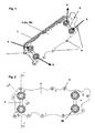
- FIG. 1 is the entire finished oil cooler 1 to see, with inserted seals 2 before it is screwed by means of the holes 5 on the housing, not shown, or on the engine block.
- the base 3a and the mounting plate 3b are according to a first embodiment, as shown here, of two different thickness, but preferably with the same outer shape, soldered together plates 3a , 3b exist. Wherein the recesses 10 are to be punched out of the mounting plate 3b for the seals 2 .
- the plates 3a , 3b can also have the same thickness.
- the inside 32 which is the side facing away from the engine block side of the mounting plate 3b is solder plated.
- FIG. 2 An exact plan view of the underside of the mounting plate 3b of the oil cooler 1 shows Fig. 2 , The sections E - E and F - F shown herein can be seen in the following figures.
- the molded lugs 29 on the outside of the seals 2 serve to pinch the seal 2 , so that they can not fall out during mounting.
- the recesses 10 for receiving the seals 2 have approximately a bone-like shape. It may also be possible, as in an embodiment not shown, another form, depending on the position of the openings 4 , 6 , which in turn is given by the shape and requirements of the engine block.
- Fig. 3a and b is the section F - F off Fig. 2 shown.
- the gasket 2 has noses 29 on the thick, annular bead 28 and is thinned in the middle 27 connecting the two annular beads 28 .
- the opening 4 , 6 has a smaller cross-section than the recess 10 at the openings 4 , 6 , so that the seal 2 can not be pressed into the oil cooler 1 inside. This achieves a tight connection between oil cooler 1 including soldered base 3a and mounting plate 3b with the engine block.
- the inside 32 of the mounting plate 3b is solder plated.
- impressions 20 for a solder deposit in the vicinity of and around the recess 10 are embossed in the fastening plate 3b .
- These impressions 20 have, as in Fig. 5 Interruptions 34 on, but they could also be consistent.
- Fig. 3b one sees the soldered oil cooler 1 with the soldered base 3a and mounting plate 3b and with the seal 2 inserted.
- Fig. 4a and b is the cut E - E off Fig. 2 shown.
- the recess 10 , 41 in the mounting plate 3b has a larger diameter than the opening 4 in the base plate 3a .
- Fig. 4b If you see the soldered oil cooler 1 with soldered base 3a and mounting plate 3b and with inserted seal. 2
- the resulting in the oil cooler 1 by the nesting of the trough-shaped heat transfer plates 9 channels 7 , 8 for the coolant and the oil have been indicated by flow arrows.
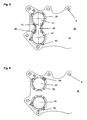
- Fig. 5 is the selected in this embodiment, the bone shape of the recess 10 to see well. It is composed of two circular openings 41 and a 41 connecting the openings slot 42nd
- the shape of the seal 2 is adapted to the shape of the recess 10 in the respective embodiment.
- the holes 43 are used for venting during the soldering process.
- Fig. 6 an alternative embodiment is shown. It shows that the recesses 10 only consist of circular openings 41 without connecting slot 42 . This can be useful depending on the requirement.
- the recesses 10 are larger than the openings 4 , 6 so that it is ensured here that the seal 2 is not pressed into the oil cooler.
- the impressions 2 0 for the solder deposit are arranged around the recesses 10 , 41 .
- the seals 2 also consist of a thick annular bead 28 with molded lugs 29 for clamping the seal 2 , during assembly of the oil cooler 1 on the engine block.
- the recesses 10 are composed of two circular recesses and a rectangular recess connecting them. This rectangular recess can also be omitted, depending on the requirement.
- the seals 2 are to be adjusted depending on the case.
Landscapes
- Engineering & Computer Science (AREA)
- Physics & Mathematics (AREA)
- Thermal Sciences (AREA)
- Mechanical Engineering (AREA)
- General Engineering & Computer Science (AREA)
- Lubrication Of Internal Combustion Engines (AREA)
- Heat-Exchange Devices With Radiators And Conduit Assemblies (AREA)
Claims (8)
- Échangeur de chaleur, en particulier refroidisseur d'huile, constitué de plaques de transfert de chaleur (1) en forme de bac empilées les unes dans les autres qui forment en alternance des canaux (7, 8) pour le réfrigérant et l'huile, ainsi que d'une plaque de base et de fixation combinée (3) dotée d'ouvertures traversantes (5) pour fixer le refroidisseur d'huile à un bloc-moteur, la plaque de base et de fixation combinée (3) comprenant deux ouvertures (4) pour le passage de l'huile, et la plaque de base et de fixation (3) étant brasée sur le paquet formé de plaques de transfert de chaleur (1), des évidements (10) pour la réception de joints d'étanchéité (2) étant prévus sur le côté de la plaque de base et de fixation combinée (3) opposé à l'échangeur de chaleur,
caractérisé en ce que la plaque de base et de fixation combinée (3) comprend également deux ouvertures (6) pour le passage du réfrigérant et est formée à partir de deux plaques en tôle (3a, 3b) jointes de même épaisseur de tôle ou d'épaisseurs de tôle différentes,
les évidements (10) dans la plaque de fixation (3b) présentant une plus grande section transversale que les ouvertures (4, 6) dans la plaque de base (3a) et s'étendant au moins autour des ouvertures (4, 6). - Échangeur de chaleur selon la revendication 1, caractérisé en ce que les évidements (10) constitués d'ouvertures (4, 6) pour le passage de l'huile et du réfrigérant ainsi que les évidements (10) pour la réception des joints d'étanchéité (2) sont découpés dans la plaque de fixation (3b).
- Échangeur de chaleur selon les revendications 1 et 2, caractérisé en ce que les ouvertures (4, 6) pour le passage de l'huile et du réfrigérant sont découpées dans la plaque de base (3a).
- Échangeur de chaleur selon l'une quelconque des revendications 1 à 3, caractérisé en ce que chaque évidement (10) est formé dans la plaque de fixation (3b) par au moins deux orifices (41) qui sont reliés par une fente (42), de telle sorte que les orifices (41) et la fente (42) présentent conjointement une configuration approximativement en forme d'os.
- Échangeur de chaleur selon l'une quelconque des revendications 1 à 4, caractérisé en ce que la plaque de base (3a) et la plaque de fixation (3b) sont plaquées de brasure sur le côté (32) tourné vers l'échangeur de chaleur.
- Échangeur de chaleur selon la revendication 5, caractérisé en ce que des empreintes (20) pour un dépôt de brasure sont prévues, pour recevoir le joint d'étanchéité (2), de préférence dans la plaque de fixation (3b) autour des évidements (10).
- Échangeur de chaleur selon l'une quelconque des revendications précédentes, caractérisé en ce que le joint d'étanchéité (2) devant être inséré dans l'évidement (10) est une pièce d'étanchéité unique à l'aide de laquelle deux ouvertures (4, 6) peuvent être fermées hermétiquement.
- Échangeur de chaleur selon l'une quelconque des revendications précédentes 1 à 6, caractérisé en ce que les joints d'étanchéité (2) devant être insérés dans l'évidement (10) sont respectivement une pièce d'étanchéité annulaire à l'aide de laquelle une ouverture (4, 6) respective peut être fermée hermétiquement.
Applications Claiming Priority (2)
| Application Number | Priority Date | Filing Date | Title |
|---|---|---|---|
| DE10347181 | 2003-10-10 | ||
| DE10347181A DE10347181B4 (de) | 2003-10-10 | 2003-10-10 | Wärmetauscher, insbesondere Ölkühler |
Publications (3)
| Publication Number | Publication Date |
|---|---|
| EP1522811A2 EP1522811A2 (fr) | 2005-04-13 |
| EP1522811A3 EP1522811A3 (fr) | 2010-09-15 |
| EP1522811B1 true EP1522811B1 (fr) | 2012-12-05 |
Family
ID=34306361
Family Applications (1)
| Application Number | Title | Priority Date | Filing Date |
|---|---|---|---|
| EP04022134A Expired - Lifetime EP1522811B1 (fr) | 2003-10-10 | 2004-09-17 | Echangeur de chaleur, en particulier refroidisseur d'huile |
Country Status (3)
| Country | Link |
|---|---|
| US (1) | US7533717B2 (fr) |
| EP (1) | EP1522811B1 (fr) |
| DE (1) | DE10347181B4 (fr) |
Cited By (2)
| Publication number | Priority date | Publication date | Assignee | Title |
|---|---|---|---|---|
| US8516699B2 (en) | 2008-04-02 | 2013-08-27 | Modine Manufacturing Company | Method of manufacturing a heat exchanger having a contoured insert |
| US9395121B2 (en) | 2007-01-23 | 2016-07-19 | Modine Manufacturing Company | Heat exchanger having convoluted fin end and method of assembling the same |
Families Citing this family (24)
| Publication number | Priority date | Publication date | Assignee | Title |
|---|---|---|---|---|
| DE10359806A1 (de) | 2003-12-19 | 2005-07-14 | Modine Manufacturing Co., Racine | Wärmeübertrager mit flachen Rohren und flaches Wärmeübertragerrohr |
| EP3276291B1 (fr) | 2005-10-05 | 2019-07-24 | Dana Canada Corporation | Échangeur thermique à plaques embouties avec élément de renfort |
| DE102005053924B4 (de) | 2005-11-11 | 2016-03-31 | Modine Manufacturing Co. | Ladeluftkühler in Plattenbauweise |
| DE102005054045A1 (de) * | 2005-11-12 | 2007-05-16 | Modine Mfg Co | Gelöteter Plattenwärmetauscher |
| DE102006005084A1 (de) * | 2006-02-04 | 2007-08-09 | Modine Manufacturing Co., Racine | Wärmetauscher, insbesondere Ölkühler |
| DE102006022445A1 (de) * | 2006-05-13 | 2007-11-15 | Modine Manufacturing Co., Racine | Wärmetauscher, insbesondere Ölkühler |
| SE531819C2 (sv) * | 2006-09-22 | 2009-08-18 | Alfa Laval Corp Ab | Plattvärmeväxlare |
| SE532084C2 (sv) | 2007-05-10 | 2009-10-20 | Alfa Laval Corp Ab | Plattvärmeväxlare |
| SE536042C2 (sv) * | 2010-06-16 | 2013-04-09 | Titanx Engine Cooling Holding Ab | Värmeväxlare med utökad värmeöverföringsyta runt fästpunkter |
| EP2413045B1 (fr) * | 2010-07-30 | 2014-02-26 | Grundfos Management A/S | Unité d'échange thermique |
| DE102010063141A1 (de) * | 2010-12-15 | 2012-06-21 | Mahle International Gmbh | Wärmetauscher |
| DE202011002197U1 (de) * | 2011-02-01 | 2012-02-02 | Dana Gmbh | Wärmetauscher |
| WO2013159172A1 (fr) * | 2012-04-26 | 2013-10-31 | Dana Canada Corporation | Échangeur de chaleur muni d'un module adaptateur |
| US20140238386A1 (en) * | 2013-02-23 | 2014-08-28 | Alexander Levin | Radiation absorbing metal pipe |
| DE102013014434A1 (de) | 2013-08-30 | 2015-03-05 | Modine Manufacturing Company | Gelöteter Wärmetauscher |
| DE102013225181A1 (de) * | 2013-12-06 | 2015-06-11 | Daimler Ag | Ölkühler für ein Kraftfahrzeug |
| EP2886996B1 (fr) * | 2013-12-20 | 2016-07-13 | Alfa Laval Corporate AB | Échangeur de chaleur à plaques avec bride de montage |
| DE102014226671A1 (de) * | 2014-12-19 | 2016-06-23 | Mahle International Gmbh | Ölkühler für ein Ölfiltermodul eines Kraftfahrzeugs |
| DE102018206574A1 (de) * | 2018-04-27 | 2019-10-31 | Mahle International Gmbh | Stapelscheibenwärmetauscher |
| DE102020203892A1 (de) * | 2019-03-29 | 2020-10-01 | Dana Canada Corporation | Tauschermodul mit einem adaptermodul zum direkten anbau an einer fahrzeugkomponente |
| CN115298508A (zh) * | 2020-03-16 | 2022-11-04 | 加特可株式会社 | 装置 |
| CN112013711A (zh) * | 2020-09-09 | 2020-12-01 | 浙江银轮机械股份有限公司 | 引流板及换热器 |
| US11633799B2 (en) * | 2020-10-01 | 2023-04-25 | Hamilton Sundstrand Corporation | Control assembly fabrication via brazing |
| EP4506649B1 (fr) * | 2023-08-11 | 2025-10-01 | Modine Manufacturing Company | Configuration d'alvéoles d'échangeur de chaleur |
Citations (1)
| Publication number | Priority date | Publication date | Assignee | Title |
|---|---|---|---|---|
| EP0623798A2 (fr) * | 1993-05-05 | 1994-11-09 | Behr GmbH & Co. | Echangeur de chaleur à plaques, en particulier refroidisseur d'huile |
Family Cites Families (25)
| Publication number | Priority date | Publication date | Assignee | Title |
|---|---|---|---|---|
| BE794794A (fr) * | 1971-11-04 | 1973-05-16 | Modine Mfg Cy | Appareil echangeur de chaleur |
| US4360055A (en) * | 1976-09-08 | 1982-11-23 | Modine Manufacturing Company | Heat exchanger |
| US4260013A (en) * | 1979-08-10 | 1981-04-07 | Hisaka Works, Limited | Plate type heat exchanger |
| JPH073315B2 (ja) * | 1985-06-25 | 1995-01-18 | 日本電装株式会社 | 熱交換器 |
| US4892136A (en) * | 1986-12-31 | 1990-01-09 | Kabushiki Kaisha Tsuchiya Seisakusho | Heat exchanger |
| DE3913100C2 (de) * | 1989-04-21 | 1994-02-17 | Laengerer & Reich Kuehler | Wärmeaustauscher, insbesondere Ölkühler |
| US4967835A (en) * | 1989-08-21 | 1990-11-06 | Modine Manufacturing Company, Inc. | Filter first donut oil cooler |
| US5099912A (en) | 1990-07-30 | 1992-03-31 | Calsonic Corporation | Housingless oil cooler |
| JP2521328Y2 (ja) * | 1990-08-06 | 1996-12-25 | カルソニック株式会社 | 自動変速機用オイルクーラ |
| US5148863A (en) * | 1992-01-15 | 1992-09-22 | Earl's Supply Co. | Modular cooler |
| US5558154A (en) * | 1992-12-01 | 1996-09-24 | Modine Manufacturing Company | Captive flow donut oil cooler |
| DE4303669C1 (de) * | 1993-02-09 | 1994-01-20 | Kyffhaeuser Maschf Artern Gmbh | Wärmeübertragungsplatte |
| DE9309741U1 (de) * | 1993-06-30 | 1993-08-26 | Filterwerk Mann & Hummel Gmbh, 71638 Ludwigsburg | Wärmetauscher |
| JP3663981B2 (ja) * | 1999-06-30 | 2005-06-22 | 株式会社デンソー | 熱交換器及びそのろう付け方法 |
| DE19519740B4 (de) | 1995-06-02 | 2005-04-21 | Mann + Hummel Gmbh | Wärmetauscher |
| DE19539255A1 (de) * | 1995-10-21 | 1997-04-24 | Laengerer & Reich Gmbh & Co | Kühler mit Filteranschluß |
| JP2829849B2 (ja) * | 1996-05-02 | 1998-12-02 | 本田技研工業株式会社 | 自動車用オイルクーラ |
| US5797450A (en) * | 1996-05-02 | 1998-08-25 | Honda Giken Kogyo Kabushiki Kaisha | Oil cooler for automobiles |
| US5964280A (en) | 1996-07-16 | 1999-10-12 | Modine Manufacturing Company | Multiple fluid path plate heat exchanger |
| DE19711258C2 (de) | 1997-03-18 | 1999-09-02 | Behr Gmbh & Co | Stapelscheiben-Ölkühler |
| DE19722074A1 (de) * | 1997-05-27 | 1998-12-03 | Knecht Filterwerke Gmbh | Plattenwärmetauscher, insbesondere Öl/Kühlmittel-Kühler für Kraftfahrzeuge |
| DE69914287T2 (de) * | 1998-11-13 | 2004-11-18 | Denso Corp., Kariya | Befestigungsvorrichtung für Ölkühler |
| JP2002168591A (ja) * | 2000-11-29 | 2002-06-14 | Denso Corp | アルミニウム製熱交換器 |
| DE10152363A1 (de) * | 2001-10-24 | 2003-05-08 | Modine Mfg Co | Gehäuseloser Plattenwärmetauscher |
| CA2383649C (fr) * | 2002-04-24 | 2009-08-18 | Long Manufacturing Ltd. | Plaque de scellement a couvercle inverse pour echangeur thermique |
-
2003
- 2003-10-10 DE DE10347181A patent/DE10347181B4/de not_active Expired - Lifetime
-
2004
- 2004-09-17 EP EP04022134A patent/EP1522811B1/fr not_active Expired - Lifetime
- 2004-10-07 US US10/960,326 patent/US7533717B2/en active Active - Reinstated
Patent Citations (1)
| Publication number | Priority date | Publication date | Assignee | Title |
|---|---|---|---|---|
| EP0623798A2 (fr) * | 1993-05-05 | 1994-11-09 | Behr GmbH & Co. | Echangeur de chaleur à plaques, en particulier refroidisseur d'huile |
Cited By (2)
| Publication number | Priority date | Publication date | Assignee | Title |
|---|---|---|---|---|
| US9395121B2 (en) | 2007-01-23 | 2016-07-19 | Modine Manufacturing Company | Heat exchanger having convoluted fin end and method of assembling the same |
| US8516699B2 (en) | 2008-04-02 | 2013-08-27 | Modine Manufacturing Company | Method of manufacturing a heat exchanger having a contoured insert |
Also Published As
| Publication number | Publication date |
|---|---|
| DE10347181B4 (de) | 2005-12-22 |
| EP1522811A3 (fr) | 2010-09-15 |
| US20050121182A1 (en) | 2005-06-09 |
| EP1522811A2 (fr) | 2005-04-13 |
| DE10347181A1 (de) | 2005-05-19 |
| US7533717B2 (en) | 2009-05-19 |
Similar Documents
| Publication | Publication Date | Title |
|---|---|---|
| EP1522811B1 (fr) | Echangeur de chaleur, en particulier refroidisseur d'huile | |
| EP0828980B1 (fr) | Echangeur de chaleur | |
| EP0623798B1 (fr) | Echangeur de chaleur à plaques, en particulier refroidisseur d'huile | |
| DE69626295T2 (de) | Plattenwärmetauscher | |
| EP1876406B1 (fr) | Agencement de filtre d'échangeur thermique, en particulier pour un véhicule automobile | |
| WO2005071342A1 (fr) | Echangeur de chaleur, notamment radiateur d'huile/de liquide de refroidissement | |
| DE112010003096T5 (de) | Wärmetauscher mit einen Befestigungsflansch vorsehender Endplatte | |
| DE102018206574A1 (de) | Stapelscheibenwärmetauscher | |
| EP1452816B1 (fr) | Echangeur de chaleur à plaques | |
| EP1855074A2 (fr) | Echangeur thermique, en particulier refroidisseur d'huile | |
| DE69208335T2 (de) | Filtersektor | |
| EP1846718B1 (fr) | Echangeur thermique | |
| EP2588826A2 (fr) | Échangeur de chaleur | |
| WO2013174914A1 (fr) | Échangeur thermique pour tempérer un premier fluide à l'aide d'un second fluide | |
| EP2498040B1 (fr) | Échangeur thermique et procédé de fabrication d'un échangeur thermique | |
| DE8429523U1 (de) | Kühlkörper für elektronische Bauelemente und/oder Geräte | |
| DE69601547T2 (de) | Wärmetauscher mit Endkammern,die mit Trennwänden versehen sind,und Verfahren zu dessen Herstellung | |
| DE69500676T2 (de) | Wärmetauscher | |
| DE60004295T2 (de) | Plattenwärmetauscher, insbesondere zum Kühlen von Kraftfahrzeugöl | |
| DE69613918T2 (de) | Wärmetauscher mit Adapter | |
| DE20121112U1 (de) | Sammelkasten für einen Wärmeaustauscher, insbesondere an Kraftfahrzeugen | |
| EP1910764A1 (fr) | Element de plaque pour refroidisseur a plaques | |
| EP2154465A2 (fr) | Echangeur thermique à plaques | |
| DE3341361C2 (de) | Radiator, insbesondere für Klimaanlagen von Kraftfahrzeugen | |
| EP1612499A2 (fr) | Echangeur de chaleur à plaques |
Legal Events
| Date | Code | Title | Description |
|---|---|---|---|
| PUAI | Public reference made under article 153(3) epc to a published international application that has entered the european phase |
Free format text: ORIGINAL CODE: 0009012 |
|
| AK | Designated contracting states |
Kind code of ref document: A2 Designated state(s): AT BE BG CH CY CZ DE DK EE ES FI FR GB GR HU IE IT LI LU MC NL PL PT RO SE SI SK TR |
|
| AX | Request for extension of the european patent |
Extension state: AL HR LT LV MK |
|
| RAP1 | Party data changed (applicant data changed or rights of an application transferred) |
Owner name: MODINE MANUFACTURING COMPANY Owner name: DAIMLERCHRYSLER AG |
|
| RAP1 | Party data changed (applicant data changed or rights of an application transferred) |
Owner name: MODINE MANUFACTURING COMPANY Owner name: DAIMLER AG |
|
| PUAL | Search report despatched |
Free format text: ORIGINAL CODE: 0009013 |
|
| AK | Designated contracting states |
Kind code of ref document: A3 Designated state(s): AT BE BG CH CY CZ DE DK EE ES FI FR GB GR HU IE IT LI LU MC NL PL PT RO SE SI SK TR |
|
| AX | Request for extension of the european patent |
Extension state: AL HR LT LV MK |
|
| 17P | Request for examination filed |
Effective date: 20110315 |
|
| AKX | Designation fees paid |
Designated state(s): AT BE BG CH CY CZ DE DK EE ES FI FR GB GR HU IE IT LI LU MC NL PL PT RO SE SI SK TR |
|
| 17Q | First examination report despatched |
Effective date: 20110519 |
|
| GRAP | Despatch of communication of intention to grant a patent |
Free format text: ORIGINAL CODE: EPIDOSNIGR1 |
|
| GRAS | Grant fee paid |
Free format text: ORIGINAL CODE: EPIDOSNIGR3 |
|
| GRAA | (expected) grant |
Free format text: ORIGINAL CODE: 0009210 |
|
| AK | Designated contracting states |
Kind code of ref document: B1 Designated state(s): DE FR GB |
|
| RBV | Designated contracting states (corrected) |
Designated state(s): DE FR GB |
|
| REG | Reference to a national code |
Ref country code: GB Ref legal event code: FG4D Free format text: NOT ENGLISH |
|
| REG | Reference to a national code |
Ref country code: DE Ref legal event code: R096 Ref document number: 502004013909 Country of ref document: DE Effective date: 20130131 |
|
| PLBE | No opposition filed within time limit |
Free format text: ORIGINAL CODE: 0009261 |
|
| STAA | Information on the status of an ep patent application or granted ep patent |
Free format text: STATUS: NO OPPOSITION FILED WITHIN TIME LIMIT |
|
| 26N | No opposition filed |
Effective date: 20130906 |
|
| REG | Reference to a national code |
Ref country code: DE Ref legal event code: R097 Ref document number: 502004013909 Country of ref document: DE Effective date: 20130906 |
|
| REG | Reference to a national code |
Ref country code: FR Ref legal event code: PLFP Year of fee payment: 12 |
|
| REG | Reference to a national code |
Ref country code: FR Ref legal event code: PLFP Year of fee payment: 13 |
|
| PGFP | Annual fee paid to national office [announced via postgrant information from national office to epo] |
Ref country code: GB Payment date: 20160927 Year of fee payment: 13 |
|
| PGFP | Annual fee paid to national office [announced via postgrant information from national office to epo] |
Ref country code: FR Payment date: 20160926 Year of fee payment: 13 |
|
| PGFP | Annual fee paid to national office [announced via postgrant information from national office to epo] |
Ref country code: DE Payment date: 20160928 Year of fee payment: 13 |
|
| REG | Reference to a national code |
Ref country code: DE Ref legal event code: R119 Ref document number: 502004013909 Country of ref document: DE |
|
| GBPC | Gb: european patent ceased through non-payment of renewal fee |
Effective date: 20170917 |
|
| REG | Reference to a national code |
Ref country code: FR Ref legal event code: ST Effective date: 20180531 |
|
| PG25 | Lapsed in a contracting state [announced via postgrant information from national office to epo] |
Ref country code: GB Free format text: LAPSE BECAUSE OF NON-PAYMENT OF DUE FEES Effective date: 20170917 Ref country code: DE Free format text: LAPSE BECAUSE OF NON-PAYMENT OF DUE FEES Effective date: 20180404 |
|
| PG25 | Lapsed in a contracting state [announced via postgrant information from national office to epo] |
Ref country code: FR Free format text: LAPSE BECAUSE OF NON-PAYMENT OF DUE FEES Effective date: 20171002 |