EP1876406B1 - Agencement de filtre d'échangeur thermique, en particulier pour un véhicule automobile - Google Patents
Agencement de filtre d'échangeur thermique, en particulier pour un véhicule automobile Download PDFInfo
- Publication number
- EP1876406B1 EP1876406B1 EP07012888.9A EP07012888A EP1876406B1 EP 1876406 B1 EP1876406 B1 EP 1876406B1 EP 07012888 A EP07012888 A EP 07012888A EP 1876406 B1 EP1876406 B1 EP 1876406B1
- Authority
- EP
- European Patent Office
- Prior art keywords
- heat exchanger
- filter
- distributor plate
- plate
- medium
- Prior art date
- Legal status (The legal status is an assumption and is not a legal conclusion. Google has not performed a legal analysis and makes no representation as to the accuracy of the status listed.)
- Not-in-force
Links
- 238000007789 sealing Methods 0.000 claims description 17
- 238000005266 casting Methods 0.000 claims description 2
- 238000001746 injection moulding Methods 0.000 claims 1
- 239000003921 oil Substances 0.000 description 36
- 229910000679 solder Inorganic materials 0.000 description 4
- 238000005476 soldering Methods 0.000 description 4
- 238000002347 injection Methods 0.000 description 3
- 239000007924 injection Substances 0.000 description 3
- 239000010705 motor oil Substances 0.000 description 3
- 239000002826 coolant Substances 0.000 description 2
- 238000001816 cooling Methods 0.000 description 2
- 238000004512 die casting Methods 0.000 description 2
- 239000007788 liquid Substances 0.000 description 2
- 238000005461 lubrication Methods 0.000 description 2
- 239000002184 metal Substances 0.000 description 2
- 230000001419 dependent effect Effects 0.000 description 1
- 239000012530 fluid Substances 0.000 description 1
- 238000004519 manufacturing process Methods 0.000 description 1
- 230000004048 modification Effects 0.000 description 1
- 238000012986 modification Methods 0.000 description 1
- 125000006850 spacer group Chemical group 0.000 description 1
- 230000007704 transition Effects 0.000 description 1
Images




Classifications
-
- F—MECHANICAL ENGINEERING; LIGHTING; HEATING; WEAPONS; BLASTING
- F28—HEAT EXCHANGE IN GENERAL
- F28F—DETAILS OF HEAT-EXCHANGE AND HEAT-TRANSFER APPARATUS, OF GENERAL APPLICATION
- F28F9/00—Casings; Header boxes; Auxiliary supports for elements; Auxiliary members within casings
- F28F9/02—Header boxes; End plates
- F28F9/0219—Arrangements for sealing end plates into casing or header box; Header box sub-elements
- F28F9/0221—Header boxes or end plates formed by stacked elements
-
- B—PERFORMING OPERATIONS; TRANSPORTING
- B01—PHYSICAL OR CHEMICAL PROCESSES OR APPARATUS IN GENERAL
- B01D—SEPARATION
- B01D35/00—Filtering devices having features not specifically covered by groups B01D24/00 - B01D33/00, or for applications not specifically covered by groups B01D24/00 - B01D33/00; Auxiliary devices for filtration; Filter housing constructions
- B01D35/30—Filter housing constructions
- B01D35/306—Filter mounting adapter
-
- F—MECHANICAL ENGINEERING; LIGHTING; HEATING; WEAPONS; BLASTING
- F01—MACHINES OR ENGINES IN GENERAL; ENGINE PLANTS IN GENERAL; STEAM ENGINES
- F01M—LUBRICATING OF MACHINES OR ENGINES IN GENERAL; LUBRICATING INTERNAL COMBUSTION ENGINES; CRANKCASE VENTILATING
- F01M11/00—Component parts, details or accessories, not provided for in, or of interest apart from, groups F01M1/00 - F01M9/00
- F01M11/03—Mounting or connecting of lubricant purifying means relative to the machine or engine; Details of lubricant purifying means
-
- F—MECHANICAL ENGINEERING; LIGHTING; HEATING; WEAPONS; BLASTING
- F28—HEAT EXCHANGE IN GENERAL
- F28D—HEAT-EXCHANGE APPARATUS, NOT PROVIDED FOR IN ANOTHER SUBCLASS, IN WHICH THE HEAT-EXCHANGE MEDIA DO NOT COME INTO DIRECT CONTACT
- F28D9/00—Heat-exchange apparatus having stationary plate-like or laminated conduit assemblies for both heat-exchange media, the media being in contact with different sides of a conduit wall
- F28D9/0031—Heat-exchange apparatus having stationary plate-like or laminated conduit assemblies for both heat-exchange media, the media being in contact with different sides of a conduit wall the conduits for one heat-exchange medium being formed by paired plates touching each other
- F28D9/0043—Heat-exchange apparatus having stationary plate-like or laminated conduit assemblies for both heat-exchange media, the media being in contact with different sides of a conduit wall the conduits for one heat-exchange medium being formed by paired plates touching each other the plates having openings therein for circulation of at least one heat-exchange medium from one conduit to another
- F28D9/005—Heat-exchange apparatus having stationary plate-like or laminated conduit assemblies for both heat-exchange media, the media being in contact with different sides of a conduit wall the conduits for one heat-exchange medium being formed by paired plates touching each other the plates having openings therein for circulation of at least one heat-exchange medium from one conduit to another the plates having openings therein for both heat-exchange media
-
- F—MECHANICAL ENGINEERING; LIGHTING; HEATING; WEAPONS; BLASTING
- F28—HEAT EXCHANGE IN GENERAL
- F28F—DETAILS OF HEAT-EXCHANGE AND HEAT-TRANSFER APPARATUS, OF GENERAL APPLICATION
- F28F19/00—Preventing the formation of deposits or corrosion, e.g. by using filters or scrapers
- F28F19/01—Preventing the formation of deposits or corrosion, e.g. by using filters or scrapers by using means for separating solid materials from heat-exchange fluids, e.g. filters
-
- B—PERFORMING OPERATIONS; TRANSPORTING
- B01—PHYSICAL OR CHEMICAL PROCESSES OR APPARATUS IN GENERAL
- B01D—SEPARATION
- B01D2201/00—Details relating to filtering apparatus
- B01D2201/40—Special measures for connecting different parts of the filter
- B01D2201/4023—Means for connecting filter housings to supports
-
- F—MECHANICAL ENGINEERING; LIGHTING; HEATING; WEAPONS; BLASTING
- F01—MACHINES OR ENGINES IN GENERAL; ENGINE PLANTS IN GENERAL; STEAM ENGINES
- F01M—LUBRICATING OF MACHINES OR ENGINES IN GENERAL; LUBRICATING INTERNAL COMBUSTION ENGINES; CRANKCASE VENTILATING
- F01M11/00—Component parts, details or accessories, not provided for in, or of interest apart from, groups F01M1/00 - F01M9/00
- F01M11/03—Mounting or connecting of lubricant purifying means relative to the machine or engine; Details of lubricant purifying means
- F01M2011/031—Mounting or connecting of lubricant purifying means relative to the machine or engine; Details of lubricant purifying means characterised by mounting means
- F01M2011/033—Mounting or connecting of lubricant purifying means relative to the machine or engine; Details of lubricant purifying means characterised by mounting means comprising coolers or heat exchangers
-
- F—MECHANICAL ENGINEERING; LIGHTING; HEATING; WEAPONS; BLASTING
- F28—HEAT EXCHANGE IN GENERAL
- F28D—HEAT-EXCHANGE APPARATUS, NOT PROVIDED FOR IN ANOTHER SUBCLASS, IN WHICH THE HEAT-EXCHANGE MEDIA DO NOT COME INTO DIRECT CONTACT
- F28D21/00—Heat-exchange apparatus not covered by any of the groups F28D1/00 - F28D20/00
- F28D2021/0019—Other heat exchangers for particular applications; Heat exchange systems not otherwise provided for
- F28D2021/008—Other heat exchangers for particular applications; Heat exchange systems not otherwise provided for for vehicles
- F28D2021/0089—Oil coolers
Definitions
- the invention relates to a heat exchanger-filter arrangement, in particular as is commonly used in motor vehicles, according to the preamble of claim 1.
- a heat exchanger which consists of a plurality of mutually parallel tubes for guiding a medium and of lamellar and perpendicular to the tubes arranged plate-shaped heat exchanger elements.
- the heat exchanger elements are fixedly connected to the tubes, which are further bent at the outer edges and scale above each other.
- the supply of the medium to be cooled takes place via pipes arranged perpendicular to the heat exchanger elements.
- These tubes open into a distributor plate, which has a liquid inlet and a liquid outlet. In the distributor plate, the inlet and / or the outlet for the cooling medium is further provided.
- a spin-on oil filter is for example from DE 40 36 191 A1 known. Such filters are usually screwed to the engine block of a motor vehicle and serve to clean the engine oil.
- FIG. 11 an exploded view of a known heat exchanger-filter assembly 101 with a stacked disc oil cooler 102 and a spin-on filter 103 is shown, wherein the oil cooler 102 is attached to an engine block (not shown) by means of a central screw 105. Between the oil cooler 102 and the filter 103, a transition region 104 is arranged, in which the oil coming from the heat exchanger on a kind of annular gap formed by the housing of the filter 103 and the corresponding outer surface of the oil cooler 102, distributed and passes through the same in the filter 103 ,
- the spin-on filter 103 which is a change part, is screwed on the outside of the central screw 105.
- the oil cooler 102 consists of a housing, the round heat exchanger plates and the terminals. Filter 103 and oil cooler 102 are stacked around the central screw 105. The flow guidance in such oil coolers allows only moderate heat exchanger performance.
- a heat exchanger-filter assembly with a heat exchanger, particularly preferably with an oil cooler, and a spin-on filter which can be screwed onto a central screw, wherein a distributor plate is provided in the flow path of the heat exchanger and the filter by flowing fluid between the heat exchanger and the filter, which is attachable by means of the central screw to a motor block, wherein the filter on the projecting through the distributor plate central screw is externally screwed and the heat exchanger laterally spaced from the central screw and is located next to the filter.
- the distributor plate according to the invention comprises three or more than three plate-shaped elements, which are formed in particular by stamped sheet metal parts, wherein in each case an inlet channel and an outlet channel is formed in a central plate-shaped element, and the outer plate-shaped elements the inlet and outlet openings for provide the conducted medium available and the middle plate-shaped element provides a deflection of the medium in a direction perpendicular to the inlet and outlet flow direction of the medium.
- the distributor plate can also be formed at least partially by a casting, in particular by a die-cast and / or injection molded part, in which channels are formed, wherein the channels provide a deflection of the medium in a direction perpendicular to the inlet and outlet flow direction of the medium.
- the arrangement of the heat exchanger next to and not stacked in series with the filter simplifies the structural design and is also - in terms of the design of the heat exchanger - more flexible.
- the heat exchanger without modification of the other components can be varied and adapted to the cooling requirements, in particular preferably by changing the number of slices.
- better cooling performance can be achieved by using stacked disc radiators compared to the known round disc radiators commonly used in this application will be realized.
- a structural change of the engine block is not required.
- the heat exchanger is preferably soldered or welded to the distributor plate or at least part of the distributor plate. Also is - preferably with the inclusion of sealing elements - a connection by means of screws possible.
- the filter is screwed onto the distributor plate in such a way that the lower edge of the filter housing bears in a sealing manner against the corresponding surface of the distributor plate.
- the distributor plate can be provided in a relatively simple manner, a clean and flat sealing surface, so that leaks can be avoided.
- the distributor plate preferably has two on one side and on the other side four inlet or outlet openings, but the number of openings can be varied, for example.
- bypass is particularly advantageous in order to be able to ensure adequate lubrication even with viscous medium, in particular during a cold start of the engine at very low ambient temperatures.
- the bypass can be realized very easily, for example by a directly through hole from the media inlet to the filter.
- a partial flow can be diverted directly to the filter before the deflection of the media flow. The partial flows are reunited in the filter and leave the same preferably via the central screw in a known manner.
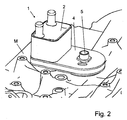
- a heat exchanger-filter assembly 1 according to the in the FIGS. 1 to 5 illustrated, the first embodiment has a heat exchanger, in this case a stacked-disk oil cooler 2, and a spin-on filter 3.
- the oil cooler 2 is in contrast to known systems connected to the filter 3 via a distributor plate 4, wherein the two components 2 and 3 are arranged on the same side of the distributor plate 4.
- the distributor plate 4 is in turn screwed by means of a central, hollow screw 5 by means of a hexagon formed on the central screw 5 and with the interposition of a seal 6 on an engine block M (see Fig. 2 ).
- the filter 3, which is a change part, is screwed onto the central screw 5 on a thread provided at its outer end, wherein when changing the filter 3, the distributor plate 4 and the oil cooler 2 remain on the engine block.
- the lower edge of the filter housing is in properly screwed filter 3 in sealing engagement with the distributor plate 4 (see Fig. 1 ).
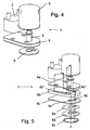
- the distributor plate 4 consists of three plate-shaped elements 4a, 4b and 4c, in the present case formed by stamped sheet-metal parts, the outer elements 4a and 4c being thinner than the inner element 4b.
- the upper plate-shaped element 4a of the distributor plate 4 has four openings through which oil can be passed into the oil cooler 2, out of the oil cooler 2, into the filter 3 and out of the filter.
- the middle plate-shaped element 4b has two slots 4b 'and 4b "and an opening for the passage of the central screw 5.
- the lower plate-shaped element 4c has two openings 4c' and 4c", the opening 4c 'of the introduction of the oil and the opening 4c "the implementation of the central screw 5 and - within the same - the discharge of the oil is used.
- the central screw 5 has an open through hole. It is provided at both ends with threaded portions and in the central region said hexagon is formed, by means of which it can be screwed firmly into the engine block M.
- the seal 6 is designed in several parts, wherein it has a solder disk 6a, a sealing seat 6b and a sealing ring 6c.
- the solder disk 6a serves to solder the distributor plate 4 and the sealing seat 6b.
- the sealing ring 6c is used to seal against the engine block M or possibly another component and is usually after soldering the sealing seat 6b with the interposition of the solder disc 6a with the distributor plate 4 and the oil cooler 2 with the distributor plate 4 and the soldering of the central screw 5 is mounted with the distributor plate 4, wherein the soldering of the components 2, 4, 5 and 6 (except the sealing ring 6c) takes place in one operation.
- the flow path of the oil coming from the engine is in Fig. 5 represented by arrows.
- the oil flows through the eccentric hole in the gasket 6 and the aperture 4c 'in the lower plate-shaped member 4c into the slit 4b' of the middle plate-shaped member 4b.
- a further flow in a straight direction is prevented by the upper plate-shaped element 4a.
- the oil is continued perpendicular to the previous flow direction until the end of the slot 4b', from where it passes through the corresponding opening in the upper plate-shaped element 4a in the oil cooler 2. After flowing through it, wherein the oil emits heat to a coolant, which also flows through the oil cooler 2, it flows - laterally offset - through a second opening in the upper plate-shaped element 4a in the second slot 4b "of the middle plate-shaped element 4b, where again At the end of the slot, the oil flows through a third opening in the upper plate-shaped element 4a to the outside of the distributor plate 4, where it is distributed over an annular gap of the filter 3 and flows through the same from the outside upwards and inwards Upper portion of the filter 3, the filtered oil passes into the running through the central screw 5 bore, which it flows through and again the engine block M is supplied.
- a second embodiment of a heat exchanger-filter assembly 1 is shown, which for setting a desired, in particular a space-related required distance between the heat exchanger-filter assembly 1 and the engine block M instead of the seal 6 of the first embodiment, a spacer and sealing element 16 with a central body 16a and two sealing rings 16 and 16c.
- the central body 16a has for receiving the sealing rings 16a and 16b at the top and bottom each have an annular groove.
- passages are provided for the oil, in the present case in the form of a region-wise annular gap-like opening and in the other areas, ie from the distributor plate 4, the second embodiment does not differ from the first embodiment, so that will not be discussed in detail.
- the distributor plate 4 is formed in the lower portion as a diecast or as an injection molded part 24a with open-topped channels, wherein the diecast part 24a is covered by a plate-shaped element 24b, which is soldered to the heat exchanger 2 and the central screw 5.
- the die-cast part 24a and the plate-like member 24b are screwed by means of four or one to four or more than four screws 24d inserted through corresponding holes in the die casting 24a and inserted through openings in the plate-shaped member 24b and into threads provided in the die-cast part 24a are firmly connected to each other in the course of a pre-assembly after the soldering of the heat exchanger 2 and the central screw 5 with the plate-shaped element 24b.
- a groove (not shown) for receiving a further sealing element 26 is provided on the die-cast part 24a below, which seals the die-cast part 24a with respect to the engine block M or another component.
- the course of the oil flow corresponds to that of the previously described embodiments, so that will not be discussed in detail.
- Fig. 8 shows as a further example not according to the invention a distributor plate 4, which is designed as a die-cast part or injection molded part 34 with closed channels.
- the heat exchanger 2 is screwed thereto with the interposition of sealing rings 34 a, which are arranged in corresponding grooves of the distributor plate 4.
- a C-shaped opening 34b for the oil inlet and in the central region a circular opening for the central screw 5 and the formed therein in the die-cast part 34 Oil drainage provided.
- Plate-shaped elements are not required due to the closed channels in this case.
- a groove (not shown) for receiving a further sealing element 36 is provided on the die casting 34 below, which seals the die-cast part 34 relative to the engine block M or another component.
- the course of the oil flow again corresponds to that of the previously described embodiments, so that will not be discussed in detail.
- a bypass 41 in the form of a series of aligned holes 41a in the distributor plate 4 and the seal 6 is formed, which - especially in extremely cold and therefore viscous oil,
- a bypass 41 in the form of a series of aligned holes 41a in the distributor plate 4 and the seal 6 is formed, which - especially in extremely cold and therefore viscous oil,
- a partial flow of oil can pass directly from the engine to the filter 3, so that an (emergency) lubrication of the engine is guaranteed.
- the rest of the oil flow flows through the heat exchanger-filter assembly 1 in the Fig. 5 illustrated way. In the filter 3 meet and unite the two oil streams again so that they flow together through the hole in the central screw 5.
- Fig. 10 shows the fourth embodiment, wherein a "small" bypass variant is provided.
- the bypass 51 branches off from the slot 4b 'in the middle plate-shaped element 4b through a provided in the upper plate-shaped element 4a bore 54a' directly into the filter 3, ie the fifth embodiment differs from the first embodiment only through the bore 54a '.
- the filter 3 meet and unite the two streams again.
Landscapes
- Engineering & Computer Science (AREA)
- Mechanical Engineering (AREA)
- General Engineering & Computer Science (AREA)
- Physics & Mathematics (AREA)
- Thermal Sciences (AREA)
- Chemical & Material Sciences (AREA)
- Chemical Kinetics & Catalysis (AREA)
- Lubrication Details And Ventilation Of Internal Combustion Engines (AREA)
- Heat-Exchange Devices With Radiators And Conduit Assemblies (AREA)
Claims (7)
- Agencement de filtre d'échangeur de chaleur comprenant au moins un échangeur de chaleur, en particulier un refroidisseur d'huile (2), et au moins un filtre de type spin-on (3) qui peut être vissé sur au moins une vis (5), où il est prévu, entre l'échangeur de chaleur au moins au nombre de un et le filtre (3) au moins au nombre de un, au moins une plaque de distribution (4) placée dans le trajet d'écoulement d'un milieu traversant le filtre (3) et l'échangeur de chaleur au moins au nombre de un, plaque de distribution qui peut être fixée sur un bloc-moteur (M) au moyen de la vis (5) au moins au nombre de un, où le filtre (3) au moins au nombre de un peut être vissé sur la vis (5) au moins au nombre de un traversant la plaque de distribution (4) au moins au nombre de un, et l'échangeur de chaleur au moins au nombre de un est disposé en étant latéralement à distance de la vis (5) au moins au nombre de un et à proximité du filtre (3) au moins au nombre de un, caractérisé en ce que la plaque de distribution (4) au moins au nombre de un présente au moins trois éléments (4a, 4b, 4c) en forme de plaque, où les éléments extérieurs (4a et 4c) en forme de plaque mettent à disposition les ouvertures d'entrée et de sortie pour le milieu en circulation, et il est prévu, dans l'élément intérieur (4b) en forme de plaque et au moins au nombre de un, un retour de flux du milieu suivant une direction perpendiculaire à la direction d'écoulement d'entrée ou de sortie du milieu au moins au nombre de un, où au moins un conduit d'entrée et au moins un conduit de sortie sont formés à chaque fois dans l'élément du milieu (4b) en forme de plaque et au moins au nombre de un.
- Agencement de filtre d'échangeur de chaleur selon la revendication 1, caractérisé en ce que la plaque de distribution (4) au moins au nombre de un est formée au moins partiellement par au moins une pièce moulée (24a ; 34), en particulier une pièce moulée par injection ou une pièce moulée sous pression, pièce moulée dans laquelle sont formés des conduits, où il est prévu, dans les conduits, un retour de flux du milieu en circulation au moins au nombre de un, suivant une direction perpendiculaire à la direction d'écoulement d'entrée ou de sortie, au moins au nombre de un, du milieu.
- Agencement de filtre d'échangeur de chaleur selon l'une des revendications précédentes, caractérisé en ce que l'échangeur de chaleur au moins au nombre de un est assemblé par continuité de matière, en particulier brasé ou soudé, avec la plaque de distribution (4) au moins au nombre de un ou avec au moins une partie de la plaque de distribution au moins au nombre de un.
- Agencement de filtre d'échangeur de chaleur selon l'une quelconque des revendications précédentes, caractérisé en ce que le filtre (3) au moins au nombre de un est vissé sur la plaque de distribution (4) au moins au nombre de un, de manière telle que le bord inférieur au moins au nombre de un du carter de filtre au moins au nombre de un soit en appui de façon étanche sur la surface correspondante de la plaque de distribution (4) au moins au nombre de un.
- Agencement de filtre d'échangeur de chaleur selon l'une quelconque des revendications précédentes, caractérisé en ce que la plaque de distribution (4) au moins au nombre de un présente, sur un côté, au moins deux et, sur l'autre côté, au moins quatre ouvertures d'entrée ou de sortie.
- Agencement de filtre d'échangeur de chaleur selon l'une quelconque des revendications précédentes, caractérisé en ce qu'au moins une dérivation (41 ; 51) est formée par rapport à l'échangeur de chaleur au moins au nombre de un, dérivation à travers laquelle une partie d'un flux d'un milieu en circulation, par laquelle peut être traversée la plaque de distribution (4) au moins au nombre de un, parvient directement dans le filtre (3) au moins au nombre de un, sans traverser l'échangeur de chaleur au moins au nombre de un.
- Agencement de filtre d'échangeur de chaleur selon l'une quelconque des revendications précédentes, caractérisé en ce que l'échangeur de chaleur au moins au nombre de un est formé par au moins un refroidisseur d'huile à plaques empilées (2).
Applications Claiming Priority (1)
| Application Number | Priority Date | Filing Date | Title |
|---|---|---|---|
| DE200610031608 DE102006031608A1 (de) | 2006-07-06 | 2006-07-06 | Wärmetauscher-Filter-Anordnung, insbesondere für ein Kraftfahrzeug |
Publications (2)
| Publication Number | Publication Date |
|---|---|
| EP1876406A1 EP1876406A1 (fr) | 2008-01-09 |
| EP1876406B1 true EP1876406B1 (fr) | 2016-09-28 |
Family
ID=38476069
Family Applications (1)
| Application Number | Title | Priority Date | Filing Date |
|---|---|---|---|
| EP07012888.9A Not-in-force EP1876406B1 (fr) | 2006-07-06 | 2007-07-02 | Agencement de filtre d'échangeur thermique, en particulier pour un véhicule automobile |
Country Status (2)
| Country | Link |
|---|---|
| EP (1) | EP1876406B1 (fr) |
| DE (1) | DE102006031608A1 (fr) |
Cited By (1)
| Publication number | Priority date | Publication date | Assignee | Title |
|---|---|---|---|---|
| DE102018119812A1 (de) | 2017-08-15 | 2019-02-21 | Mann+Hummel Gmbh | Kunststoffbauteil-Metallbauteil-Kombination |
Families Citing this family (15)
| Publication number | Priority date | Publication date | Assignee | Title |
|---|---|---|---|---|
| DE102008031684B4 (de) | 2008-07-04 | 2020-02-06 | Mahle International Gmbh | Kühleinrichtung |
| DE102008052259A1 (de) * | 2008-10-18 | 2010-04-22 | Mahle International Gmbh | Filtereinrichtung |
| DE102009050016A1 (de) | 2009-05-27 | 2011-05-05 | Modine Manufacturing Co., Racine | Wärmeübertragereinheit |
| DE102009022919A1 (de) * | 2009-05-27 | 2010-12-02 | Modine Manufacturing Co., Racine | Wärmeübertragereinheit |
| DE102010026507A1 (de) * | 2010-07-07 | 2012-01-12 | Behr Gmbh & Co. Kg | Kältemittelkondensatormodul |
| DE202011002197U1 (de) | 2011-02-01 | 2012-02-02 | Dana Gmbh | Wärmetauscher |
| WO2013159172A1 (fr) | 2012-04-26 | 2013-10-31 | Dana Canada Corporation | Échangeur de chaleur muni d'un module adaptateur |
| DE102015221478A1 (de) * | 2015-11-03 | 2017-05-04 | Mahle International Gmbh | Flanschvorrichtung für einen Wärmetauscher |
| IT201600115641A1 (it) * | 2016-11-16 | 2018-05-16 | Ufi Filters Spa | Un assieme di filtrazione e regolazione della temperatura olio motore |
| JP6646569B2 (ja) * | 2016-12-28 | 2020-02-14 | 株式会社クボタ | エンジン |
| DE102018119600B4 (de) * | 2018-08-13 | 2021-06-02 | Mann+Hummel Gmbh | Ölfiltermodul mit Wärmeübertrager |
| DE102020203892A1 (de) | 2019-03-29 | 2020-10-01 | Dana Canada Corporation | Tauschermodul mit einem adaptermodul zum direkten anbau an einer fahrzeugkomponente |
| US20220196348A1 (en) * | 2019-04-19 | 2022-06-23 | Ufi Filters S.P.A. | Support and connection device |
| DE102022211833A1 (de) | 2022-11-09 | 2024-05-16 | Mahle International Gmbh | Vorrichtung für ein Kraftfahrzeug |
| DE102024120889A1 (de) * | 2024-07-23 | 2026-01-29 | Mahle International Gmbh | Wärmeübertragermodul, brennkratmaschine und kraftfahrzeug |
Family Cites Families (10)
| Publication number | Priority date | Publication date | Assignee | Title |
|---|---|---|---|---|
| BE794794A (fr) * | 1971-11-04 | 1973-05-16 | Modine Mfg Cy | Appareil echangeur de chaleur |
| FR2569767B1 (fr) * | 1984-09-04 | 1988-12-02 | Chausson Usines Sa | Dispositif regulateur de pression et de derivation pour circuit de lubrification de moteurs thermiques |
| DE4036191A1 (de) * | 1990-08-14 | 1992-02-20 | Reinhard Weber | Zerlegbarer spin-on-oelfilter |
| US5351664A (en) * | 1993-04-16 | 1994-10-04 | Kohler Co. | Oil cooling device |
| DE19519740B4 (de) * | 1995-06-02 | 2005-04-21 | Mann + Hummel Gmbh | Wärmetauscher |
| DE19626867A1 (de) * | 1996-07-04 | 1998-01-29 | Daimler Benz Ag | An ein Kurbelgehäuse eines Verbrennungsmotors anflanschbares Trägerteil für Aggregate der Schmier-Ölversorgung und -behandlung |
| DE10245005A1 (de) * | 2002-09-26 | 2004-04-08 | Mann + Hummel Gmbh | Flüssigkeitsfilter-Wärmetauscher-Einheit |
| JP4354252B2 (ja) * | 2002-10-29 | 2009-10-28 | 川崎重工業株式会社 | オイルクーラ及び小型走行船 |
| DE202004015748U1 (de) * | 2004-10-12 | 2006-02-23 | Hengst Gmbh & Co.Kg | Ölmodul mit Dichtungen in einer Dichtebene |
| DE102005012550A1 (de) * | 2005-03-18 | 2006-09-21 | Mahle International Gmbh | Filter-Kühler-Kombination für Flüssigkeiten, insbesondere Schmieröl eines Kraftfahrzeug-Verbrennungsmotors |
-
2006
- 2006-07-06 DE DE200610031608 patent/DE102006031608A1/de not_active Withdrawn
-
2007
- 2007-07-02 EP EP07012888.9A patent/EP1876406B1/fr not_active Not-in-force
Cited By (1)
| Publication number | Priority date | Publication date | Assignee | Title |
|---|---|---|---|---|
| DE102018119812A1 (de) | 2017-08-15 | 2019-02-21 | Mann+Hummel Gmbh | Kunststoffbauteil-Metallbauteil-Kombination |
Also Published As
| Publication number | Publication date |
|---|---|
| DE102006031608A1 (de) | 2008-01-17 |
| EP1876406A1 (fr) | 2008-01-09 |
Similar Documents
| Publication | Publication Date | Title |
|---|---|---|
| EP1876406B1 (fr) | Agencement de filtre d'échangeur thermique, en particulier pour un véhicule automobile | |
| EP2205922B1 (fr) | Échangeur thermique, notamment refroidisseur à huile | |
| EP0828980B1 (fr) | Echangeur de chaleur | |
| DE102009050696B4 (de) | Wärmetauscher-Einheit mit Umgehungsventil | |
| DE19703042B4 (de) | Strömungsregelvorrichtung | |
| EP1522811B1 (fr) | Echangeur de chaleur, en particulier refroidisseur d'huile | |
| EP1559980B1 (fr) | Echangeur de chaleur à plaques | |
| DE102019128897A1 (de) | Mehrwegeventil, Fluidkreislauf und Kühlfluidkreislauf | |
| EP1664659B1 (fr) | Module a huile destine a un moteur a combustion interne | |
| EP1711698A1 (fr) | Ensemble soupape thermostatique | |
| EP1735074A1 (fr) | Ensemble filtre-radiateur destine a des liquides, notamment a l'huile lubrifiante du moteur a combustion d'un vehicule automobile | |
| EP2588826A2 (fr) | Échangeur de chaleur | |
| EP1124105B1 (fr) | Système de refroidissement de liquide | |
| EP1769207B1 (fr) | Echangeur thermique a plaques | |
| DE102017219433A1 (de) | Wärmeübertrager für einen Verbrennungsmotor | |
| DE102015106476B4 (de) | Schmierölsystem einer Brennkraftmaschine | |
| DE112005002226T5 (de) | Plattenwärmetauscher und Plattenmodul | |
| EP0819906B1 (fr) | Raccord adaptateur pour échangeur de chaleur à plaques | |
| DE102004049292A1 (de) | Zylinderkopfdichtung | |
| DE102005002063A1 (de) | Stapelscheiben -Wärmetauscher | |
| DE202006015673U1 (de) | Modularer Ventilblock | |
| EP1904720B1 (fr) | Refroidisseur d'huile | |
| DE102006027725A1 (de) | Einrichtung mit einem Wärmetauscher und einem Flüssigkeitsfilter | |
| EP1651328A1 (fr) | Filtre a liquide pour moteur a combustion interne | |
| EP0893667A2 (fr) | Echangeur de chaleur à plaques,sans caisson |
Legal Events
| Date | Code | Title | Description |
|---|---|---|---|
| PUAI | Public reference made under article 153(3) epc to a published international application that has entered the european phase |
Free format text: ORIGINAL CODE: 0009012 |
|
| AK | Designated contracting states |
Kind code of ref document: A1 Designated state(s): AT BE BG CH CY CZ DE DK EE ES FI FR GB GR HU IE IS IT LI LT LU LV MC MT NL PL PT RO SE SI SK TR |
|
| AX | Request for extension of the european patent |
Extension state: AL BA HR MK YU |
|
| 17P | Request for examination filed |
Effective date: 20080709 |
|
| 17Q | First examination report despatched |
Effective date: 20080811 |
|
| AKX | Designation fees paid |
Designated state(s): AT BE BG CH CY CZ DE DK EE ES FI FR GB GR HU IE IS IT LI LT LU LV MC MT NL PL PT RO SE SI SK TR |
|
| RAP1 | Party data changed (applicant data changed or rights of an application transferred) |
Owner name: MAHLE BEHR GMBH & CO. KG |
|
| GRAP | Despatch of communication of intention to grant a patent |
Free format text: ORIGINAL CODE: EPIDOSNIGR1 |
|
| RIC1 | Information provided on ipc code assigned before grant |
Ipc: B01D 35/30 20060101ALI20160314BHEP Ipc: F28D 9/00 20060101AFI20160314BHEP Ipc: F28F 19/01 20060101ALI20160314BHEP Ipc: F28F 9/02 20060101ALI20160314BHEP Ipc: F01M 11/03 20060101ALI20160314BHEP |
|
| INTG | Intention to grant announced |
Effective date: 20160421 |
|
| GRAS | Grant fee paid |
Free format text: ORIGINAL CODE: EPIDOSNIGR3 |
|
| GRAA | (expected) grant |
Free format text: ORIGINAL CODE: 0009210 |
|
| RIN1 | Information on inventor provided before grant (corrected) |
Inventor name: SCHLEIER, GERD Inventor name: RICHTER, JENS |
|
| AK | Designated contracting states |
Kind code of ref document: B1 Designated state(s): AT BE BG CH CY CZ DE DK EE ES FI FR GB GR HU IE IS IT LI LT LU LV MC MT NL PL PT RO SE SI SK TR |
|
| REG | Reference to a national code |
Ref country code: GB Ref legal event code: FG4D Free format text: NOT ENGLISH |
|
| REG | Reference to a national code |
Ref country code: CH Ref legal event code: EP |
|
| REG | Reference to a national code |
Ref country code: AT Ref legal event code: REF Ref document number: 833135 Country of ref document: AT Kind code of ref document: T Effective date: 20161015 |
|
| REG | Reference to a national code |
Ref country code: IE Ref legal event code: FG4D Free format text: LANGUAGE OF EP DOCUMENT: GERMAN |
|
| REG | Reference to a national code |
Ref country code: DE Ref legal event code: R096 Ref document number: 502007015140 Country of ref document: DE |
|
| REG | Reference to a national code |
Ref country code: LT Ref legal event code: MG4D |
|
| PG25 | Lapsed in a contracting state [announced via postgrant information from national office to epo] |
Ref country code: FI Free format text: LAPSE BECAUSE OF FAILURE TO SUBMIT A TRANSLATION OF THE DESCRIPTION OR TO PAY THE FEE WITHIN THE PRESCRIBED TIME-LIMIT Effective date: 20160928 Ref country code: LT Free format text: LAPSE BECAUSE OF FAILURE TO SUBMIT A TRANSLATION OF THE DESCRIPTION OR TO PAY THE FEE WITHIN THE PRESCRIBED TIME-LIMIT Effective date: 20160928 |
|
| REG | Reference to a national code |
Ref country code: NL Ref legal event code: MP Effective date: 20160928 |
|
| PG25 | Lapsed in a contracting state [announced via postgrant information from national office to epo] |
Ref country code: GR Free format text: LAPSE BECAUSE OF FAILURE TO SUBMIT A TRANSLATION OF THE DESCRIPTION OR TO PAY THE FEE WITHIN THE PRESCRIBED TIME-LIMIT Effective date: 20161229 Ref country code: SE Free format text: LAPSE BECAUSE OF FAILURE TO SUBMIT A TRANSLATION OF THE DESCRIPTION OR TO PAY THE FEE WITHIN THE PRESCRIBED TIME-LIMIT Effective date: 20160928 Ref country code: LV Free format text: LAPSE BECAUSE OF FAILURE TO SUBMIT A TRANSLATION OF THE DESCRIPTION OR TO PAY THE FEE WITHIN THE PRESCRIBED TIME-LIMIT Effective date: 20160928 Ref country code: NL Free format text: LAPSE BECAUSE OF FAILURE TO SUBMIT A TRANSLATION OF THE DESCRIPTION OR TO PAY THE FEE WITHIN THE PRESCRIBED TIME-LIMIT Effective date: 20160928 |
|
| PG25 | Lapsed in a contracting state [announced via postgrant information from national office to epo] |
Ref country code: EE Free format text: LAPSE BECAUSE OF FAILURE TO SUBMIT A TRANSLATION OF THE DESCRIPTION OR TO PAY THE FEE WITHIN THE PRESCRIBED TIME-LIMIT Effective date: 20160928 Ref country code: RO Free format text: LAPSE BECAUSE OF FAILURE TO SUBMIT A TRANSLATION OF THE DESCRIPTION OR TO PAY THE FEE WITHIN THE PRESCRIBED TIME-LIMIT Effective date: 20160928 |
|
| PG25 | Lapsed in a contracting state [announced via postgrant information from national office to epo] |
Ref country code: BG Free format text: LAPSE BECAUSE OF FAILURE TO SUBMIT A TRANSLATION OF THE DESCRIPTION OR TO PAY THE FEE WITHIN THE PRESCRIBED TIME-LIMIT Effective date: 20161228 Ref country code: SK Free format text: LAPSE BECAUSE OF FAILURE TO SUBMIT A TRANSLATION OF THE DESCRIPTION OR TO PAY THE FEE WITHIN THE PRESCRIBED TIME-LIMIT Effective date: 20160928 Ref country code: IS Free format text: LAPSE BECAUSE OF FAILURE TO SUBMIT A TRANSLATION OF THE DESCRIPTION OR TO PAY THE FEE WITHIN THE PRESCRIBED TIME-LIMIT Effective date: 20170128 Ref country code: PL Free format text: LAPSE BECAUSE OF FAILURE TO SUBMIT A TRANSLATION OF THE DESCRIPTION OR TO PAY THE FEE WITHIN THE PRESCRIBED TIME-LIMIT Effective date: 20160928 Ref country code: CZ Free format text: LAPSE BECAUSE OF FAILURE TO SUBMIT A TRANSLATION OF THE DESCRIPTION OR TO PAY THE FEE WITHIN THE PRESCRIBED TIME-LIMIT Effective date: 20160928 Ref country code: PT Free format text: LAPSE BECAUSE OF FAILURE TO SUBMIT A TRANSLATION OF THE DESCRIPTION OR TO PAY THE FEE WITHIN THE PRESCRIBED TIME-LIMIT Effective date: 20170130 Ref country code: ES Free format text: LAPSE BECAUSE OF FAILURE TO SUBMIT A TRANSLATION OF THE DESCRIPTION OR TO PAY THE FEE WITHIN THE PRESCRIBED TIME-LIMIT Effective date: 20160928 |
|
| REG | Reference to a national code |
Ref country code: DE Ref legal event code: R097 Ref document number: 502007015140 Country of ref document: DE |
|
| PG25 | Lapsed in a contracting state [announced via postgrant information from national office to epo] |
Ref country code: IT Free format text: LAPSE BECAUSE OF FAILURE TO SUBMIT A TRANSLATION OF THE DESCRIPTION OR TO PAY THE FEE WITHIN THE PRESCRIBED TIME-LIMIT Effective date: 20160928 |
|
| REG | Reference to a national code |
Ref country code: FR Ref legal event code: PLFP Year of fee payment: 11 |
|
| PG25 | Lapsed in a contracting state [announced via postgrant information from national office to epo] |
Ref country code: DK Free format text: LAPSE BECAUSE OF FAILURE TO SUBMIT A TRANSLATION OF THE DESCRIPTION OR TO PAY THE FEE WITHIN THE PRESCRIBED TIME-LIMIT Effective date: 20160928 |
|
| PLBE | No opposition filed within time limit |
Free format text: ORIGINAL CODE: 0009261 |
|
| STAA | Information on the status of an ep patent application or granted ep patent |
Free format text: STATUS: NO OPPOSITION FILED WITHIN TIME LIMIT |
|
| 26N | No opposition filed |
Effective date: 20170629 |
|
| PG25 | Lapsed in a contracting state [announced via postgrant information from national office to epo] |
Ref country code: SI Free format text: LAPSE BECAUSE OF FAILURE TO SUBMIT A TRANSLATION OF THE DESCRIPTION OR TO PAY THE FEE WITHIN THE PRESCRIBED TIME-LIMIT Effective date: 20160928 |
|
| REG | Reference to a national code |
Ref country code: CH Ref legal event code: PL |
|
| GBPC | Gb: european patent ceased through non-payment of renewal fee |
Effective date: 20170702 |
|
| REG | Reference to a national code |
Ref country code: IE Ref legal event code: MM4A |
|
| PG25 | Lapsed in a contracting state [announced via postgrant information from national office to epo] |
Ref country code: IE Free format text: LAPSE BECAUSE OF NON-PAYMENT OF DUE FEES Effective date: 20170702 Ref country code: GB Free format text: LAPSE BECAUSE OF NON-PAYMENT OF DUE FEES Effective date: 20170702 Ref country code: LI Free format text: LAPSE BECAUSE OF NON-PAYMENT OF DUE FEES Effective date: 20170731 Ref country code: CH Free format text: LAPSE BECAUSE OF NON-PAYMENT OF DUE FEES Effective date: 20170731 |
|
| REG | Reference to a national code |
Ref country code: BE Ref legal event code: MM Effective date: 20170731 |
|
| PG25 | Lapsed in a contracting state [announced via postgrant information from national office to epo] |
Ref country code: LU Free format text: LAPSE BECAUSE OF NON-PAYMENT OF DUE FEES Effective date: 20170702 |
|
| REG | Reference to a national code |
Ref country code: FR Ref legal event code: PLFP Year of fee payment: 12 |
|
| PG25 | Lapsed in a contracting state [announced via postgrant information from national office to epo] |
Ref country code: BE Free format text: LAPSE BECAUSE OF NON-PAYMENT OF DUE FEES Effective date: 20170731 |
|
| REG | Reference to a national code |
Ref country code: AT Ref legal event code: MM01 Ref document number: 833135 Country of ref document: AT Kind code of ref document: T Effective date: 20170702 |
|
| PG25 | Lapsed in a contracting state [announced via postgrant information from national office to epo] |
Ref country code: MT Free format text: LAPSE BECAUSE OF FAILURE TO SUBMIT A TRANSLATION OF THE DESCRIPTION OR TO PAY THE FEE WITHIN THE PRESCRIBED TIME-LIMIT Effective date: 20160928 |
|
| PGFP | Annual fee paid to national office [announced via postgrant information from national office to epo] |
Ref country code: IT Payment date: 20180925 Year of fee payment: 12 |
|
| PG25 | Lapsed in a contracting state [announced via postgrant information from national office to epo] |
Ref country code: AT Free format text: LAPSE BECAUSE OF NON-PAYMENT OF DUE FEES Effective date: 20170702 |
|
| PG25 | Lapsed in a contracting state [announced via postgrant information from national office to epo] |
Ref country code: MC Free format text: LAPSE BECAUSE OF FAILURE TO SUBMIT A TRANSLATION OF THE DESCRIPTION OR TO PAY THE FEE WITHIN THE PRESCRIBED TIME-LIMIT Effective date: 20160928 Ref country code: HU Free format text: LAPSE BECAUSE OF FAILURE TO SUBMIT A TRANSLATION OF THE DESCRIPTION OR TO PAY THE FEE WITHIN THE PRESCRIBED TIME-LIMIT; INVALID AB INITIO Effective date: 20070702 |
|
| PG25 | Lapsed in a contracting state [announced via postgrant information from national office to epo] |
Ref country code: CY Free format text: LAPSE BECAUSE OF NON-PAYMENT OF DUE FEES Effective date: 20160928 |
|
| PGFP | Annual fee paid to national office [announced via postgrant information from national office to epo] |
Ref country code: DE Payment date: 20190919 Year of fee payment: 13 |
|
| PG25 | Lapsed in a contracting state [announced via postgrant information from national office to epo] |
Ref country code: TR Free format text: LAPSE BECAUSE OF FAILURE TO SUBMIT A TRANSLATION OF THE DESCRIPTION OR TO PAY THE FEE WITHIN THE PRESCRIBED TIME-LIMIT Effective date: 20160928 |
|
| PG25 | Lapsed in a contracting state [announced via postgrant information from national office to epo] |
Ref country code: FR Free format text: LAPSE BECAUSE OF NON-PAYMENT OF DUE FEES Effective date: 20190731 |
|
| REG | Reference to a national code |
Ref country code: DE Ref legal event code: R119 Ref document number: 502007015140 Country of ref document: DE |
|
| PG25 | Lapsed in a contracting state [announced via postgrant information from national office to epo] |
Ref country code: DE Free format text: LAPSE BECAUSE OF NON-PAYMENT OF DUE FEES Effective date: 20210202 |