EP1522897A2 - Système de formation d'images - Google Patents
Système de formation d'images Download PDFInfo
- Publication number
- EP1522897A2 EP1522897A2 EP04023393A EP04023393A EP1522897A2 EP 1522897 A2 EP1522897 A2 EP 1522897A2 EP 04023393 A EP04023393 A EP 04023393A EP 04023393 A EP04023393 A EP 04023393A EP 1522897 A2 EP1522897 A2 EP 1522897A2
- Authority
- EP
- European Patent Office
- Prior art keywords
- developer
- regenerator
- unit
- replenisher
- printing plate
- Prior art date
- Legal status (The legal status is an assumption and is not a legal conclusion. Google has not performed a legal analysis and makes no representation as to the accuracy of the status listed.)
- Withdrawn
Links
Images
Classifications
-
- G—PHYSICS
- G03—PHOTOGRAPHY; CINEMATOGRAPHY; ANALOGOUS TECHNIQUES USING WAVES OTHER THAN OPTICAL WAVES; ELECTROGRAPHY; HOLOGRAPHY
- G03F—PHOTOMECHANICAL PRODUCTION OF TEXTURED OR PATTERNED SURFACES, e.g. FOR PRINTING, FOR PROCESSING OF SEMICONDUCTOR DEVICES; MATERIALS THEREFOR; ORIGINALS THEREFOR; APPARATUS SPECIALLY ADAPTED THEREFOR
- G03F7/00—Photomechanical, e.g. photolithographic, production of textured or patterned surfaces, e.g. printing surfaces; Materials therefor, e.g. comprising photoresists; Apparatus specially adapted therefor
- G03F7/26—Processing photosensitive materials; Apparatus therefor
- G03F7/30—Imagewise removal using liquid means
- G03F7/3042—Imagewise removal using liquid means from printing plates transported horizontally through the processing stations
- G03F7/3071—Process control means, e.g. for replenishing
-
- G—PHYSICS
- G03—PHOTOGRAPHY; CINEMATOGRAPHY; ANALOGOUS TECHNIQUES USING WAVES OTHER THAN OPTICAL WAVES; ELECTROGRAPHY; HOLOGRAPHY
- G03F—PHOTOMECHANICAL PRODUCTION OF TEXTURED OR PATTERNED SURFACES, e.g. FOR PRINTING, FOR PROCESSING OF SEMICONDUCTOR DEVICES; MATERIALS THEREFOR; ORIGINALS THEREFOR; APPARATUS SPECIALLY ADAPTED THEREFOR
- G03F7/00—Photomechanical, e.g. photolithographic, production of textured or patterned surfaces, e.g. printing surfaces; Materials therefor, e.g. comprising photoresists; Apparatus specially adapted therefor
- G03F7/26—Processing photosensitive materials; Apparatus therefor
- G03F7/30—Imagewise removal using liquid means
- G03F7/3042—Imagewise removal using liquid means from printing plates transported horizontally through the processing stations
Definitions
- a lithographic printing plate is composed of ink receptive regions, commonly referred to as the "image area,” and hydrophilic regions.
- image area When the surface of the printing plate is moistened with water and printing ink is applied, the hydrophilic regions retain the water and repel the printing ink, and the image area retains the printing ink and repels the water.
- the printing ink retained on the image area may then be transferred to the surface of a material upon which the image is to be reproduced.
- the ink is first transferred to an intermediate blanket, which in turn transfers the ink to the desired surface.
- Lithographic printing plates precursors typically include a radiation-sensitive coating applied over the hydrophilic surface of a substrate.
- Conventional radiation-sensitive coatings include photosensitive components dispersed within an organic polymeric binder. After a portion of the coating is exposed to radiation (commonly referred to as imagewise exposure), the exposed portion becomes either more developable or less developable in a particular liquid than an unexposed portion of the coating.
- a printing plate precursor is generally considered a positive-working plate if, after exposure to radiation, the exposed portions or areas of the radiation-sensitive coating become more developable and are removed in the developing process to reveal the hydrophilic surface. Conversely, the precursor is considered a negative-working plate if the exposed portions or areas become less developable in the developer and the unexposed portions or areas are removed in the developing process.
- the precursors are contacted with a developer to remove either the exposed or unexposed portions of the radiation-sensitive coating to form a printing plate.
- This process is generally performed using a developer system, which receives imaged printing plate precursors, and then contacts the precursors with a developer either by spraying the developer onto the precursor or by immersing the precursor in a developer bath.
- a developer system which receives imaged printing plate precursors, and then contacts the precursors with a developer either by spraying the developer onto the precursor or by immersing the precursor in a developer bath.
- portions of the radiation-sensitive composition are removed from the precursor to reveal the substrate surface, and portions remain on the plate to provide an ink-receptive image.
- the used developer is then filtered and reused to develop additional precursors. Examples of developers used in such processes include 956 brand developer, MX 1813 brand developer and Aqua-Image brand developer, all of which are available from Kodak Polychrome Graphics.
- the activity of a developer may vary due to the depletion of, or changes in, various components of the developer.
- concentration of the active solvent or the dispersing agent may become depleted.
- the pH of the developer may vary. Changes in developer activity may be caused by loss of developer volume as printing plates carry developer out of the developer apparatus. Additionally, interactions with the radiation-sensitive coatings of the printing plate precursors may also affect developer activity. In particular, the pH of the developer may change due to acid/base interactions with radiation-sensitive coatings. This loss of developer activity may result in inconsistency in overall dot density over a cycle of developed printing plates, which may have adverse effects during printing.
- regenerator refers to a substance having approximately the same activity as the developer.
- the developer itself is often used as a replenisher to maintain the volume of developer contained in the developer system.
- regenerator refers to a substance having a different level of activity than the developer to which it is added.
- the regenerator may have a different pH or solvent concentration than the developer. Examples of such regenerators include 9008 brand regenerator, MX 1919 brand regenerator and Aqua-Image Top-Off brand regenerator, all available from Kodak Polychrome Graphics.
- development systems have been configured to include a vessel to house either replenisher or regenerator, and a conduit for controllably delivering replenisher or regenerator to the developer.
- a vessel to house either replenisher or regenerator
- a conduit for controllably delivering replenisher or regenerator to the developer.
- the present invention provides a system for developing printing plate precursors.
- the system includes a developer unit adapted to apply a developer to the printing plate precursors, a replenisher unit adapted to controllably deliver replenisher to the developer unit, and a regenerator unit adapted to controllably deliver the regenerator to the developer unit.
- the developer unit may include a developing area adapted to receive printing plate precursors and to apply developer to the precursors, and a circulation unit adapted to receive developer from, and deliver developer to the developing area.
- the circulation unit may include a developer vessel adapted to receive developer from the developing area.
- the developer vessel may also receive replenisher delivered from the replenisher unit and/or regenerator delivered from the regenerator unit.
- the circulation unit may further include a developer filter positioned between the developing area and the developer vessel, as well as one or more controllable conduits adapted to provide fluid communication between the developing area and the developer vessel.
- the replenisher unit may include a replenisher vessel to house replenisher and one or more controllable conduits to provide liquid communication between the replenisher unit and the developer unit.
- the regenerator may include a regenerator vessel to house regenerator, and one or more controllable conduits adapted to provide liquid communication between the regenerator unit and the developer unit.
- the system may also include one or more sensors to facilitate controlled delivery of the replenisher and/or the regenerator to the developer unit.
- a sensor is adapted to monitor developer activity, such as the pH or the conductivity of the developer.
- a sensor is adapted to monitor the number of printing plate precursors developed and/or the total area of developed precursor. Multiple sensors may be used in certain embodiments.
- the sensors may electronically communicate with the replenisher unit and/or the regenerator unit to deliver effective amounts of replenisher and/or regenerator to maintain developer activity.
- the present invention also provides a method for treating a developer after developing a portion of at least one printing plate precursor.
- the method includes controllably delivering to the developer unit an effective amount of replenisher and regenerator to maintain developer activity, for example, the solvent concentration, the dispersing agent concentration, the pH or the conductivity of the developer.
- the replenisher and/or regenerator may be delivered as a function of developer activity, as a function of developed precursor area or a combination thereof.
- the present invention provides a system for developing printing plate precursors including a developer unit, a means for controllably delivering replenisher to the developer unit, and a means for controllably delivering regenerator to the developer unit.
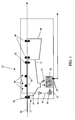
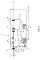
- Conventional developer systems such as the developer system 10 illustrated in Figure 1 includes a developer unit 15 which applies developer 14 to printing plate precursors 16.
- the developer unit 15 includes a developing area 12 which receives the precursors 16, brushes 21 to scrub the precursors 16, and sprayers 38 to apply or contact the aqueous developer 14 to the surface of the precursors 16.
- One or more guide rollers 18 drive and/or guide the precursors 16 through the developing area 12.
- a water rinse tank 28 is adapted to remove excess developer from the developed printing plate.
- One or more rollers 22 serve to remove remaining developer 14 from the precursor 16 before the precursor 16 enters the water rinse tank 28.
- the developer system may also include a unit at the exit of the rinse tank 28 (not shown) that applies a gum or other desensitizer to protect the surface of developed printing plate.
- the developer unit 15 further includes a circulation unit 30, which includes a developer vessel 32, a pump 34 and a filtration system 36.
- Conduit 31 connects the developing area 12 to the developer vessel 32, and outlet 23 drains excess solution from the developer vessel 32.
- the developer vessel 32 is connected to pump 34 via conduit 33.
- pump 34 When pump 34 is activated, developer is delivered from the developer, vessel 32, through conduit 35 and filter 36.
- the developer then flows through conduit 37 to spray bars 38 in the developing area 12, where developer 14 is applied to the printing plate precursor 16. In this manner, developer 14 may be applied to printing plate precursors 16, filtered and then reused to develop additional printing plate precursors 16.
- conventional developer systems may also include a replenisher unit 50, including a replenisher vessel 60, which is connected to developer vessel 32 via conduit 45 that includes pump 44.
- the replenisher unit 50 is adapted to controllably deliver replenisher to the developer unit 12.
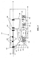
- FIG. 3 illustrates a developer system 100 according to an embodiment of the present invention.
- the developer system 100 in this embodiment includes both a replenisher unit 150 and a regenerator unit 165.
- the regenerator unit 165 includes a regenerator container 170 which is connected to developer vessel 132 via conduit 155 that include pump 154.
- a standpipe 124 is positioned relative to developer vessel 132 so that excess solution in the developer vessel 132 may be disposed of.
- the developer vessel 132 may also include an appropriate mixing device (not shown) to mix the replenisher and/or regenerator as it is added to the developer vessel 132.
- the developer system illustrated in Figure 3 is adapted to controllably deliver both replenisher and regenerator to maintain the activity of the developer.
- the developer unit 115 includes one or more sensors 139 for monitoring the volume or level of the developer in the developer vessel 132. If the developer volume or level is too low, the sensors 139 communicate with the replenisher unit 150 and/or the regenerator unit 165 to supplement the developer with replenisher and/or regenerator. Alternatively, sensors 139 may monitor the developed precursor area or number of developed precursors, and then communicate with the replenisher unit 150 and/or regenerator unit 165 to add a volume of replenisher and/or regenerator to the developer vessel 132 as a function of unit area of developed precursor.
- replenisher and/or regenerator may be added as a function of the speed at which the developer system 100 develops the precursors 16.
- pumps 144 and/or 154 may be set to deliver a volume of replenisher and/or regenerator at predetermined time intervals.
- one or more sensors 139 may monitor the activity of the developer 114.
- sensors 139 may monitor the pH or conductivity of the developer. If the activity varies beyond a certain amount, the sensors 139 communicate with one or both of the replenisher unit 150 and or the regenerator unit 165 to add additional replenisher and/or regenerator.
- the sensors 139 may be configured to electronically communicate with pumps 144 and/or 154 to deliver the replenisher and/or the regenerator.
- Suitable sensor systems are available from Oakton Instruments, Vernen Hills, IL, and include the D.A.M. and Q.D.M. brand systems.
- An example of a particular pH sensor is the OAKTON pH/ORP Controller 800 series, available from Oakton Instruments.
- a sensor 139 may monitor the number of plates or total plate area that has been developed to deliver a volume of replenisher per unit area of plate (or number of precursors) developed.
- the regenerator may be added to the developer vessel 132 by utilizing a pH sensor that communicates with pump 154 to deliver regenerator when the pH varies beyond a certain level.
- the system 100 does not necessarily deliver replenisher and regenerator in the same amounts or at the same time.
- the system 100 may provide for controlled delivery of the replenisher and the regenerator in different ways, so long as the system is capable of controllably delivering both replenisher and regenerator to the developer unit 112.
- the replenisher and/or regenerator may be added directly to the developer vessel 132.
- the replenisher and/or regenerator may be added to the developer at virtually any point after the developing area 12.
- the developer system 100 could be modified to accommodate a developer unit 115 that applies developer by sending the printing plate precursors through a developer bath, rather than by spray application.
- the circulation unit 130 may be positioned within the bath of developer to receive and deliver developer to the developing area.
- the developer system 100 could be modified to develop 2-sided plates by adding additional sprayers 138 or by re-configuring the developer bath.
- the developer system 100 could be configured to include multiple developing areas 112 such that printing plate precursors 116 are developed in multiple stages.
- the multiple developing areas 112 could be configured such that spent developer from the developing areas 112 is circulated into a first developing area, while the replenisher and regenerator are added only to remaining developing areas. In this manner, the final developing area or areas utilize developer having the desired level of activity.
- the specific amount of regenerator and/or replenisher sufficient to maintain developer activity will vary based on a number of factors apparent to those of skill in the art. Such factors include the volume and specific type of developer, the composition of the printing plate precursors, the composition of the regenerator, the frequency of regenerator addition, the activity level being measured, and the surface area of printing plate precursors being developed. Furthermore, the developer system of the present invention is adapted to be used with a variety of developers, replenishers and regenerators to develop various types of printing plate precursors.
- the developer is capable of developing printing plate precursors subjected to laser imaging, more particularly infrared laser imaging.
- the internal test pattern contained 1, 2, 3, 5, 10, 15, 20, 30, 40, 45, 50, 55, 60, 70, 80, 85, 90, 95, 98, 99, 99.5 and 100 percent dot images.
- the image-wise exposure was carried out using both Creo Staccato (FM) 10 micron and 20 micron screening.
- the resulting imaged precursor was developed using an 850 Sword II plate processor, an 850 mm width processor as supplied by Glunz and Jensen, Elkwood, VA., in the following configuration:
- the processor had been recently cleaned and new developer and filters installed. Plate resolution was then measured using a X-Rite 528 densitometer (CannonDirect, Bethel, Ohio).
- the internal test pattern for each precursor included 50 percent dot images.
- the image-wise exposure for portions of each plate precursor was carried out using Creo Staccato (FM) 10 micron screening, Creo Staccato (FM) 20 micron screening and conventional (AM ) 200 lines/inch screening.
- a 7500 square foot (in 100 square foot increments) cycle of bulk precursor imaged using a 100 percent exposure pattern was developed with an 85 NS plate processor, available from Technical Services International, Kennett Square, PA, which was modified to include a regenerator unit as shown in Figure 3, and an OAKTON pH/ORP Controller 800 Series pH sensor (in-line, continuous) from Oakton Instruments, Vernon Hills, IL.
- the processor was further modified to include a standpipe in the developer vessel (Fig. 3) to maintain a substantially constant volume.
- the modified processor was then configured as follows:
- Regenerator 1 Water 601.88g Silicone Antifoam Agent - DC Antifoam B - 15% 0.10g Sodium Octyl Sulfate - 42% 120.50g Sodium Methylnaphthalenesulfonate - 50% 88.90g Triton H-66 - 42% 24.00g Diethanolamine - 85% 12.00g Trisodium Phosphate - 43.12% 9.20g Sodium Hydroxide - 50% 50.00g p-Toluenesulfonic Acid 0.92g 2-Phenoxyethanol 44.20g EDTA Tetra Sodium Salt 7.70g Glycerin - 99.7% 40.60g Total 1000.00g pH 13.30 Conductivity (mS) 91.30,
- DC Antifoam B is available from Dow.
- Silicone Anti Foam Agent SE 57 is available from BYK Chemie, Wallingford, Connecticut.
- Triton H-66 is a phosphate ester available from Dow.
- Precursors A, B and C were developed after 1000,4000 and 7000 ft 2 , respectively, of bulk precursor had been developed.
- replenisher was added to the developer unit at a rate of about 2 ml per square foot of image precursor that was developed.
- Regenerator 1 was added to the developer as a function of the pH of the developer in the system. More particularly, the pH sensor was configured to electronically communicate with the regenerator pump when the pH of the developer dropped below 9.89.
- Table 3 shows the amount of regenerator used during the cycle, which averaged about 2 ml of regenerator per square foot of imaged precursor. The amount of regenerator used was measured by monitoring volume loss in the regenerator vessel.
- the dot density variation shown in Table 4 constitutes a significant improvement over the variation shown in Example 1, and is an acceptable level of variation in pre-press environment in many commercial applications.
Landscapes
- Physics & Mathematics (AREA)
- General Physics & Mathematics (AREA)
- Engineering & Computer Science (AREA)
- Automation & Control Theory (AREA)
- Photosensitive Polymer And Photoresist Processing (AREA)
- Dry Development In Electrophotography (AREA)
Applications Claiming Priority (2)
| Application Number | Priority Date | Filing Date | Title |
|---|---|---|---|
| US10/681,575 US20050076801A1 (en) | 2003-10-08 | 2003-10-08 | Developer system |
| US681575 | 2003-10-08 |
Publications (2)
| Publication Number | Publication Date |
|---|---|
| EP1522897A2 true EP1522897A2 (fr) | 2005-04-13 |
| EP1522897A3 EP1522897A3 (fr) | 2005-11-02 |
Family
ID=34314127
Family Applications (1)
| Application Number | Title | Priority Date | Filing Date |
|---|---|---|---|
| EP04023393A Withdrawn EP1522897A3 (fr) | 2003-10-08 | 2004-10-01 | Système de formation d'images |
Country Status (2)
| Country | Link |
|---|---|
| US (1) | US20050076801A1 (fr) |
| EP (1) | EP1522897A3 (fr) |
Cited By (1)
| Publication number | Priority date | Publication date | Assignee | Title |
|---|---|---|---|---|
| US7153045B2 (en) | 2005-01-07 | 2006-12-26 | Eastman Kodak Company | Electro-mechanical system and method for mixing replenishment for plate precursor developers |
Families Citing this family (3)
| Publication number | Priority date | Publication date | Assignee | Title |
|---|---|---|---|---|
| JP2004212681A (ja) * | 2002-12-27 | 2004-07-29 | Fuji Photo Film Co Ltd | 感光性平版印刷版の自動現像方法及びその自動現像装置 |
| US8170875B2 (en) * | 2005-06-15 | 2012-05-01 | Qnx Software Systems Limited | Speech end-pointer |
| JP4815270B2 (ja) * | 2005-08-18 | 2011-11-16 | 富士フイルム株式会社 | 平版印刷版の作製方法及び作製装置 |
Family Cites Families (34)
| Publication number | Priority date | Publication date | Assignee | Title |
|---|---|---|---|---|
| US4025344A (en) * | 1972-08-31 | 1977-05-24 | E. I. Du Pont De Nemours And Company | Lithographic developer replenishment process |
| USRE30123E (en) * | 1972-09-11 | 1979-10-23 | E. I. Du Pont De Nemours And Company | Apparatus for controlling addition of replenishment solution to a photographic processor |
| GB2046931B (en) * | 1979-02-27 | 1983-03-16 | Fuji Photo Film Co Ltd | Method of developing positive-acting photosensitive lithographic printing plate precursor |
| ATE49066T1 (de) * | 1982-10-21 | 1990-01-15 | Vickers Plc | Verarbeitung von lichtempfindlichen vorrichtungen. |
| DE3789634T2 (de) * | 1986-06-27 | 1994-08-04 | Fuji Photo Film Co Ltd | Verfahren zum Zuführen von Regenerationsflüssigkeit in einem automatischen Entwicklungsgerät. |
| JPH03107167A (ja) * | 1989-09-20 | 1991-05-07 | Fuji Photo Film Co Ltd | 感光材料処理装置 |
| US5480762A (en) * | 1990-11-28 | 1996-01-02 | Fuji Photo Film Co., Ltd. | Method for preparing lithographic printing plate |
| JP2561578B2 (ja) * | 1991-08-07 | 1996-12-11 | 株式会社平間理化研究所 | 現像液管理装置 |
| DE4204691A1 (de) * | 1992-02-17 | 1993-09-02 | Hoechst Ag | Verfahren und vorrichtung zum entwickeln von strahlungsempfindlichen, belichteten druckformen |
| US5479233A (en) * | 1992-07-06 | 1995-12-26 | Fuji Photo Film Co., Ltd. | Photosensitive lithographic printing plate processing apparatus |
| US5416552A (en) * | 1994-01-28 | 1995-05-16 | Surface Tek, Inc. | Apparatus and method for replenishing developer |
| JP3278280B2 (ja) * | 1994-03-08 | 2002-04-30 | 富士写真フイルム株式会社 | 感光性平版印刷版 |
| US5811224A (en) * | 1994-08-24 | 1998-09-22 | Bayer Corporation | Process for rejuvenating developer in printing plate development |
| EP0716347B1 (fr) * | 1994-12-06 | 2002-07-24 | Fuji Photo Film Co., Ltd. | Révélateur pour matériel d'impression lithographique |
| JP3534211B2 (ja) * | 1995-09-29 | 2004-06-07 | 富士写真フイルム株式会社 | 感光性平版印刷版の自動現像装置 |
| US5766826A (en) * | 1996-10-11 | 1998-06-16 | Eastman Kodak Company | Alkaline developing composition and method of use to process lithographic printing plates |
| US6352812B1 (en) * | 1998-06-23 | 2002-03-05 | Kodak Polychrome Graphics Llc | Thermal digital lithographic printing plate |
| US6352811B1 (en) * | 1998-06-23 | 2002-03-05 | Kodak Polychrome Graphics Llc | Thermal digital lithographic printing plate |
| US6143479A (en) * | 1999-08-31 | 2000-11-07 | Kodak Polychrome Graphics Llc | Developing system for alkaline-developable lithographic printing plates |
| US6255042B1 (en) * | 1999-11-24 | 2001-07-03 | Kodak Polychrome Graphics, Llc | Developing system for alkaline-developable lithographic printing plates with different interlayers |
| EP1117007A3 (fr) * | 1999-12-08 | 2002-08-21 | Fuji Photo Film Co., Ltd. | Appareil et procédé de développement pour matériaux photosensibles |
| US6294311B1 (en) * | 1999-12-22 | 2001-09-25 | Kodak Polychrome Graphics Llc | Lithographic printing plate having high chemical resistance |
| US6528228B2 (en) * | 1999-12-22 | 2003-03-04 | Kodak Polychrome Graphics, Llc | Chemical resistant underlayer for positive-working printing plates |
| CN1267790C (zh) * | 2000-01-31 | 2006-08-02 | 富士胶片株式会社 | 自动显影装置及补充显影补充液的方法 |
| US6309792B1 (en) * | 2000-02-18 | 2001-10-30 | Kodak Polychrome Graphics Llc | IR-sensitive composition and use thereof for the preparation of printing plate precursors |
| EP1172699B1 (fr) * | 2000-07-14 | 2013-09-11 | FUJIFILM Corporation | Procédé pour la fabrication des plaques lithographiques |
| US6555291B1 (en) * | 2000-08-14 | 2003-04-29 | Kodak Polychrome Graphics, Llc | Thermal digital lithographic printing plate |
| US6391530B1 (en) * | 2000-11-03 | 2002-05-21 | Kodak Polychrome Graphics, Llc | Process for developing exposed radiation-sensitive printing plate precursors |
| JP4064055B2 (ja) * | 2000-12-08 | 2008-03-19 | 富士フイルム株式会社 | 平版印刷版の製版方法 |
| US6541188B2 (en) * | 2001-05-11 | 2003-04-01 | Kodak Polychrome Graphics Llc | Developer for alkaline-developable lithographic printing plates |
| US6562555B2 (en) * | 2001-08-01 | 2003-05-13 | Kodak Polychrome Graphics Llc | Method for developing lithographic printing plate precursors using a coating attack-suppressing agent |
| US6921620B2 (en) * | 2001-08-21 | 2005-07-26 | Kodak Polychrome Graphics Llc | Imageable composition containing colorant having a counter anion derived from a non-volatile acid |
| US6756183B2 (en) * | 2001-08-24 | 2004-06-29 | Fuji Photo Film Co., Ltd. | Method for preparing lithographic printing plate |
| US6759185B2 (en) * | 2001-11-14 | 2004-07-06 | Kodak Polychrome Graphics Llc | Method for reuse of loaded developer |
-
2003
- 2003-10-08 US US10/681,575 patent/US20050076801A1/en not_active Abandoned
-
2004
- 2004-10-01 EP EP04023393A patent/EP1522897A3/fr not_active Withdrawn
Cited By (1)
| Publication number | Priority date | Publication date | Assignee | Title |
|---|---|---|---|---|
| US7153045B2 (en) | 2005-01-07 | 2006-12-26 | Eastman Kodak Company | Electro-mechanical system and method for mixing replenishment for plate precursor developers |
Also Published As
| Publication number | Publication date |
|---|---|
| EP1522897A3 (fr) | 2005-11-02 |
| US20050076801A1 (en) | 2005-04-14 |
Similar Documents
| Publication | Publication Date | Title |
|---|---|---|
| US20070172776A1 (en) | Developer regenerators | |
| EP1434101B1 (fr) | Procédé de traitement automatique d'une plaque d'impression lithographique photosensible | |
| EP1522897A2 (fr) | Système de formation d'images | |
| EP0247835B1 (fr) | Procédé pour le traitement des plaques lithographiques présensibilisées et appareil à cet effet | |
| US7153045B2 (en) | Electro-mechanical system and method for mixing replenishment for plate precursor developers | |
| WO2008060406A2 (fr) | Procédé de préparation de plaques d'impression lithographique | |
| EP2221670A2 (fr) | Appareil de développement automatique et procédé de traitement pour précurseur de plaque d'impression lithographique | |
| US6300034B1 (en) | Processing method and apparatus for imaged elements | |
| JP2534102B2 (ja) | 感光性平版印刷版現像処理装置 | |
| JP4980821B2 (ja) | 平版印刷版処理装置 | |
| EP2103993A1 (fr) | Traitement automatique pour fabriquer une plaque d'impression lithographique | |
| JP3361613B2 (ja) | 平版印刷版用水洗水及び平版印刷版の製版方法 | |
| JP2577615B2 (ja) | 感光性平版印刷版の製版方法 | |
| JPS6234429B2 (fr) | ||
| JP2532275B2 (ja) | 感光性平版印刷版自動現像機の現像補充液補充方法 | |
| JP3628369B2 (ja) | 電子写真平版印刷版の処理方法及び溶出装置 | |
| JP3231061B2 (ja) | 電子写真平版印刷版処理装置 | |
| JPH10207078A (ja) | 感光性平版印刷版の自動現像装置 | |
| JPH06161161A (ja) | 電子写真平版印刷版の処理方法 | |
| JPH08123040A (ja) | 感光性平版印刷版用現像液 | |
| JPH1039518A (ja) | 現像処理機の洗浄方法 | |
| JPH05249696A (ja) | 水なし平版印刷版の製版方法および製版装置 | |
| JPH0778632B2 (ja) | 現像の均一性が改良される非銀塩感光材料の現像処理方法 | |
| WO2019065051A1 (fr) | Équipement de traitement pour plaque d'impression planographique photosensible et procédé de traitement de plaque d'impression planographique photosensible | |
| JPH03288155A (ja) | 感光性平版印刷版の処理方法及び処理装置 |
Legal Events
| Date | Code | Title | Description |
|---|---|---|---|
| PUAI | Public reference made under article 153(3) epc to a published international application that has entered the european phase |
Free format text: ORIGINAL CODE: 0009012 |
|
| AK | Designated contracting states |
Kind code of ref document: A2 Designated state(s): AT BE BG CH CY CZ DE DK EE ES FI FR GB GR HU IE IT LI LU MC NL PL PT RO SE SI SK TR |
|
| AX | Request for extension of the european patent |
Extension state: AL HR LT LV MK |
|
| RAP1 | Party data changed (applicant data changed or rights of an application transferred) |
Owner name: KODAK POLYCHROME GRAPHICS, LLC |
|
| PUAL | Search report despatched |
Free format text: ORIGINAL CODE: 0009013 |
|
| AK | Designated contracting states |
Kind code of ref document: A3 Designated state(s): AT BE BG CH CY CZ DE DK EE ES FI FR GB GR HU IE IT LI LU MC NL PL PT RO SE SI SK TR |
|
| AX | Request for extension of the european patent |
Extension state: AL HR LT LV MK |
|
| AKX | Designation fees paid |
Designated state(s): AT BE BG CH CY CZ DE DK EE ES FI FR GB GR HU IE IT LI LU MC NL PL PT RO SE SI SK TR |
|
| STAA | Information on the status of an ep patent application or granted ep patent |
Free format text: STATUS: THE APPLICATION IS DEEMED TO BE WITHDRAWN |
|
| 18D | Application deemed to be withdrawn |
Effective date: 20060503 |