EP1522907B1 - Steuergerät mit Zeitmessfunktion - Google Patents
Steuergerät mit Zeitmessfunktion Download PDFInfo
- Publication number
- EP1522907B1 EP1522907B1 EP20040023912 EP04023912A EP1522907B1 EP 1522907 B1 EP1522907 B1 EP 1522907B1 EP 20040023912 EP20040023912 EP 20040023912 EP 04023912 A EP04023912 A EP 04023912A EP 1522907 B1 EP1522907 B1 EP 1522907B1
- Authority
- EP
- European Patent Office
- Prior art keywords
- time measuring
- microcomputer
- counter
- control device
- turned
- Prior art date
- Legal status (The legal status is an assumption and is not a legal conclusion. Google has not performed a legal analysis and makes no representation as to the accuracy of the status listed.)
- Expired - Lifetime
Links
Images


Classifications
-
- G—PHYSICS
- G04—HOROLOGY
- G04F—TIME-INTERVAL MEASURING
- G04F10/00—Apparatus for measuring unknown time intervals by electric means
- G04F10/04—Apparatus for measuring unknown time intervals by electric means by counting pulses or half-cycles of an AC
-
- G—PHYSICS
- G06—COMPUTING OR CALCULATING; COUNTING
- G06F—ELECTRIC DIGITAL DATA PROCESSING
- G06F1/00—Details not covered by groups G06F3/00 - G06F13/00 and G06F21/00
- G06F1/04—Generating or distributing clock signals or signals derived directly therefrom
- G06F1/14—Time supervision arrangements, e.g. real time clock
Definitions
- the present invention relates to a time measuring technique for use in a control device.
- An engine electronic control unit has recently faced a demand for control to measure a time during which an engine has stopped. Measuring a time during which an ignition switch is turned off, i.e., a time during which the engine electronic control unit is stopped, is required to predict, based on the time from the preceding engine stop, a cooling level of the engine and the amounts by which engine oil has dropped and restored, and then to modify control parameters at the next engine startup.
- Patent Reference 1 JP,A 2002-341067 .
- a dedicated circuit comprising a comparator, a capacitor, etc. is provided to measure a turned-off time of an ignition switch.
- a microcomputer is started up at intervals of a constant time to measure the charging/discharging time of the capacitor and the number of times at which the capacitor has been charged and discharged, and the turned-off time of the ignition switch is measured by counting the number of times at which the capacitor has been charged and discharged.
- the disclosed method has a possibility of deterioration in accuracy of the time measurement because it utilizes the charging/discharging of the capacitor.
- Another problem is that the microcomputer is started up to count the number of times at which the capacitor has been charged and discharged, a consumption current increases during the operation of the microcomputer.
- the disclosed method has just means for measuring the turned-off time of the ignition switch. In other words, because the disclosed method cannot measure a time during which the engine has operated, it is impossible to calculate the lifetime up to now which is required to predict aging and other secular changes of engine auxiliaries, etc.
- EP 0681272 A relates to an apparatus and a method for determining a time that a system's main power was inactive.
- Said apparatus includes a counter-circuit for accumulating transitions of the clock signal while the system's main power is inactive. Furthermore, periodicity of the clock signal is determined after the system's main power transition is active,
- an object of the present invention to measure a turned-off time of an ignition switch with a low consumption current and high accuracy at a level adapted for a demand from the controlling side, as well as a turned-on time of the ignition switch. Another object of the present invention is to measure an accumulative turned-on time of the ignition switch.
- the resent invention provides a control device according to claim 1.
- the turned-off time of the ignition switch can be measured with a low consumption current and high accuracy at a level adapted for a demand from the controlling side. Further, the turned-on time of an ignition switch can be measured, and an accumulative turned-on time of the ignition switch can also be stored.
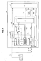
- Fig. 1 is a block diagram of a control device showing one embodiment of the present invention.
- a control device (electronic control unit (ECU)) 2 has at least two inputs for a power supply line 1a directly connected to a battery 1 and a signal line to receive a signal 3a from an ignition switch 3.
- ECU electronic control unit
- a voltage of the battery 1 is supplied to a regulator 4 and a timer module 11.
- Source power from the battery 1 can be supplied to the regulator 4 and the timer module 11 regardless of whether the ignition switch 3 is turned on or off.
- the ignition switch signal 3a is supplied to the timer module 11 and a microcomputer 7 in the control device 2.
- the timer module 11 and the microcomputer 7 determine whether the ignition switch 3 is turned on or off.
- the timer module 11 comprises an oscillator (OSC) 5, a power controller 6, an SPI 8, an oscillator controller 9, and a timer 10.
- the microcomputer 7 is associated with an oscillator 12 serving as a clock source.
- the clock sources for the timer module 11 and the microcomputer 7 are constituted by the respective oscillators 5, 12 different from each other, and the timer module 11 and the microcomputer 7 are implemented as individual devices. Data is transmitted and received between the timer module 11 and the microcomputer 7 via a communication line 7a.
- An electrically rewritable nonvolatile memory 13 stores a program executed by the microcomputer 7, and also has an area in which measured timer values are written.
- the timer module 11 is completely independent of the microcomputer 7 and can be operated even when no power is supplied to the microcomputer 7. Thus, when time measurement is performed by the timer module 11 while the control device 2 is stopped, no power is supplied to the microcomputer 7. Accordingly, a consumption current can be reduced. While the nonvolatile memory 13 is shown as being present externally of the microcomputer 7 in this embodiment, the nonvolatile memory 13 may be incorporated in the microcomputer 7.
- the ignition switch signal 3a is inputted to the power controller 6 in the timer module 11.
- the power controller 6 starts up the regulator 4.
- the microcomputer 7 When the regulator 4 is started up, a predetermined voltage is supplied to the power supply line 4a and the microcomputer 7 starts the operation.
- the microcomputer 7 recognizes the turning-on of the ignition switch signal 3a and starts up an OS (Operating System). Also, the power controller 6 receives a power hold signal 8a from the microcomputer 7 through the SPI 8.
- the power hold signal 8a is supplied from the microcomputer 7 to the SPI 8 via the communication line 7a extending between them, and then inputted to the power controller 6 after being decoded in the SPI 8.
- the power hold signal 8a is used to execute a key-off sequence in the microcomputer 7 when the ignition switch 3 is turned off.
- the microcomputer 7 recognizes the turning-off of the ignition switch 3 based on the ignition switch signal 3a, it executes the key-off sequence.
- the timer 10 for measuring time operates with the oscillator 5 serving as a clock source.
- a counter value of the time measuring timer 10 is sent to the microcomputer 7 via a counter signal line 10a, the SPI 8 and the SPI communication line 7a, thus enabling the microcomputer 7 to read the counter value.
- the operation of the time measuring timer 10 is controlled by the microcomputer 7 through the SPI 8 in accordance with a value of a timer start signal 8b.
- the value of the timer start signal 8b controls the run/stop of the time measuring timer 10.
- the time measuring timer 10 starts the operation while receiving, as a clock source, a clock signal 5a from the oscillator 5. As a result, the timer 10 is able to measure time.
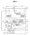
- Fig. 2 is a block diagram showing a detailed internal configuration of the regulator 4, the oscillator 5, the power controller 6, the oscillator controller 9, and the time measuring timer 10.
- the regulator 4 used in this embodiment is a linear regulator, but another type regulator, e.g., a switching regulator, can also be used.
- a transistor 21 is controlled by an error amplifier 25 so that the predetermined voltage is outputted to the power supply line 4a.
- the voltage of the power supply line 4a is compared in the error amplifier 25 with a band gap reference 26 as an absolute reference voltage.
- a control signal 25a from the error amplifier 25 is outputted to the transistor 21 through a pre-driver 28 for the transistor 21.
- a gate voltage of the transistor 21 is thereby linearly controlled to produce the predetermined voltage.
- the power control signal 6a from the power controller 6 is inputted to the pre-driver 28 to control the run/stop of the regulator 4.
- a power-on reset unit 30 initializes a counter 37 of the time measuring timer 10, etc. provided in the control device 2 so that the control device 2 is brought into an initial state when the battery 1 is connected.
- the power controller 6 determines the operation based on two input signals, i.e., the ignition switch signal 3a and the power hold signal 8a.
- the ignition switch signal 3a is directly inputted to an OR gate 31.
- the power hold signal 8a from the microcomputer 7 is inputted to the OR gate 31 through the SPI 8.
- the oscillator controller 9 comprises an overflow sensor 34 and a controller 36.
- the controller 36 controls the operations of both the oscillator 5 and the time measuring timer 10 in accordance with two input signals, i.e., the overflow signal 34a and the timer start signal 8b.
- the oscillator 5 operates at oscillation frequency of 32.768 kHz, for example.
- the time measuring timer 10 comprises a frequency divider 38 and the counter 37.
- the oscillation frequency of 32.768 kHz from the oscillator 5 is divided to 1/2 15 by the frequency divider 38 so that the LSB of the counter 37 is one second from the viewpoint of control demand.
- the counter 37 is constituted as an 18-bit counter.
- Fig. 3 is a table showing run/stop states of the oscillator 5 in accordance with the timer start signal 8b from the microcomputer 7 and the overflow signal 34a from the time measuring timer 10. The following description is made of, in particular, the case in which the ignition switch 3 is turned off, i.e., the regulator 4 is stopped.
- the timer function of this embodiment is able to measure the turned-off time of the ignition switch 3 for h'3FFFF seconds, i.e., 72.8 hours, with a resolution of one second.
- the overflow is sensed by the overflow sensor 34 to hold the count value of the counter 37, and at the same time the oscillator 5 is stopped. (See state 47)
- the stop of the oscillator 5 brings the consumption current into the same state as 45, whereby the consumption current is minimized.
- this embodiment can provide a process capable of measuring the turned-off time of the ignition switch 3 until 72.8 hours with a resolution of one second, and reducing the consumption current after the measurement for 72.8 hours.
- the counter 37 continues the count-up. Unless the microcomputer 7 stops the operation of the counter 37 of the time measuring timer 10, the counter 37 successively counts up one per second even after the ignition switch signal 3a has been turned on.
- Fig. 4 illustrates state transitions of the oscillator 5 and the time measuring timer 10 during the turned-off period of the ignition switch 3.
- An initial state is denoted by 51.
- the battery 1 In the initial state 51, the battery 1 is in a shutdown state. Therefore, the voltage of the power supply line 1a is 0 V and all the functions of the control device 2 are stopped. When the battery 1 is connected, the voltage of the power supply line 1a rises to a battery voltage.
- the counter 37 of the time measuring timer 10 starts the count-up from 1 (state 53). If the counter 37 starts the count-up from 0, the microcomputer 7 reads 0 when it reads the timer value, i.e., the count value of the counter 37, before counting one second.
- the microcomputer 7 may erroneously recognize that battery disconnection has occurred.
- the state automatically transits to 54 in which the counter 37 successively counts up one per second until reaching h'3FFFF.
- the control device fails to function (state 51).
- the controller 36 waits for clearing of the timer start signal 8b to 0.
- the state transits to 56 while the count value of the counter 37 is held.
- the controller 36 waits for setting of the timer start signal 8b to 1.
- the timer start signal 8b 1 is set, the counter 37 is initialized for transition to the state 53 for the count-up from 1. The counter 37 then starts the count-up from 1.
- the control device fails to function and the state transits to 51.
- the oscillator 5 is operated in the states 53, 54, and the oscillator 5 is stopped in the states 52, 55 and 56.
- the states 53, 54 each represent a state in which the turned-off time of the ignition switch 3 is measured with a low consumption current
- the states 52, 55 and 56 each represent a state in which the oscillator is also stopped and the consumption current is minimized.
- Fig. 5 is a time-serial waveform chart showing the operating state of the time measuring timer 10.
- the voltage of the power supply line 1a rises to the voltage of the battery 1.
- the counter 37 of the time measuring timer 10 is initialized to 0 by the power-on reset unit 30 in the regulator 4.
- the turned-on time of the ignition switch 3 can be measured with the count-up made by the counter 37 of the time measuring timer 10.
- a period from timing 63 to 64 represents a steady state in which ordinary engine control is performed. During such a period, the counter 37 of the time measuring timer 10 continues to count up one per second for time measurement.
- the microcomputer 7 recognizes the turning-off of the ignition switch 3 and executes control to stop the engine. Thereafter, the microcomputer 7 executes a process of storing data into a backup RAM and each self-diagnosis process in key-off sequence.
- the microcomputer 7 reads the count value of the counter 37 of the time measuring timer 10 through the SPI 8. Simultaneously, the counter 37 of the time measuring timer 10 is stopped in a state holding the count value.
- the microcomputer 7 In order to store the ignition turned-on time of a vehicle, i.e., the lifetime during which the engine has actually operated, the microcomputer 7 writes, in the nonvolatile memory 13, the sum of the read count value and the time stored in the nonvolatile memory 13. The foregoing is a process for storing the measurement result of the ignition turned-on time.
- the turned-off time of the ignition switch 3 can be measured with the count-up made by the counter 37 of the time measuring timer 10. This time measurement can be realized with a low consumption current because the oscillator 5, the time measuring timer 10, and the oscillator controller 9 are only operated.
- the regulator 4 When the ignition switch 3 is turned on at timing 66, the regulator 4 is started up, thus resulting in a state in which the output voltage 4a of the regulator 4 rises to the predetermined voltage as in the process at the timing 62.
- the microcomputer 7 first stops the counter 37 of the time measuring timer 10.
- the microcomputer 7 can measure the turned-off time of the ignition switch 3.
- a period from timing 67 to 68 represents, like the period from timing 63 to 64, a steady state in which ordinary engine control is performed. During such a period, the counter 37 of the time measuring timer 10 continues to count up one per second for time measurement.
- the microcomputer 7 recognizes the turning-off of the ignition switch 3 and executes control to stop the engine.
- the microcomputer 7 reads the count value of the counter 37 of the time measuring timer 10 through the SPI 8. Simultaneously, the counter 37 of the time measuring timer 10 is stopped in a state holding the count value.
- the microcomputer 7 In order to store the ignition turned-on time of the vehicle, i.e., the lifetime during which the engine has actually operated, the microcomputer 7 writes, in the nonvolatile memory 13, the sum of the read count value and the time stored in the nonvolatile memory 13. The foregoing is a process for storing the measurement result of the ignition turned-on time.
- Timing 70 represents a point in time at which the counter 37 of the time measuring timer 10 has measured the turned-off time of the ignition switch 3 for 72.8 hours, i.e., h'3FFFF seconds.
- the control signals 36a, 36b completely stop the oscillator 5 and the counter 37, respectively.
- the consumption current can be further reduced.
- a process executed during a period from timing 71 to 72 is basically the same as that executed during a period from timing 66 to 67. During the period from timing 71 to 72, the process differs only in level change of the overflow signal 34a as follows.
- the overflow signal 34a causes the timer start signal 8b to change from 0 to 1 at the timing 72 and is cleared when the counter 37 of the time measuring timer 10 is restarted.
- Fig. 6 is a flowchart of the process executed by the time measuring timer 10 when the microcomputer 7 is started up.
- the ignition switch 3 is turned on and the regulator 4 starts the operation
- the predetermined voltage is outputted to the power supply line 4a and the microcomputer 7 starts the operation.
- step 93 the microcomputer 7 reads the count value of the counter 37 of the time measuring timer 10 through the SPI 8.
- Step 96 the microcomputer 7 recognizes the result of the time measurement during the turned-off period of the ignition switch 3. Then, based on the turned-off time of the ignition switch 3, the microcomputer 7 predicts the amount by which engine oil has dropped, and computes control parameters at the next engine startup in consideration of the predicted amount.
- step 96 The reading process of the time measuring timer 10 at the startup of the microcomputer 7 is completed with step 96.
- Fig. 7 is a flowchart of the process executed by the time measuring timer 10 when the microcomputer 7 is stopped.
- the microcomputer 7 detects the turning-off of the ignition switch 3, the microcomputer 7 executes the engine control stopping process, the backup storing process, the self-diagnosis process in key-off sequence, and so on.
- step 102 the microcomputer 7 reads the count value of the counter 37 of the time measuring timer 10 through the SPI 8.
- the microcomputer 7 adds the accumulative turned-on time of the ignition switch 3 stored in the nonvolatile memory 13 and the count value of the counter 37 of the time measuring timer 10 which has been read in step 102, thereby calculating the engine lifetime.
- the calculated result is written in the nonvolatile memory 13 in step 104.
- the control device 2 can recognize the accumulative turned-on time of the ignition switch 3, i.e., the engine lifetime, and can calculate parameter values adapted for aging and other secular changes of engine auxiliaries, etc. As a result, the engine control can be properly modified.
- step 106 the power supply is shut down in step 106.
Landscapes
- Engineering & Computer Science (AREA)
- Physics & Mathematics (AREA)
- General Physics & Mathematics (AREA)
- Theoretical Computer Science (AREA)
- Power Engineering (AREA)
- General Engineering & Computer Science (AREA)
- Measurement Of Unknown Time Intervals (AREA)
- Combined Controls Of Internal Combustion Engines (AREA)
- Electric Clocks (AREA)
Claims (9)
- Steuergerät mit Zeitmessfunktion, wobei das Steuergerät Folgendes umfasst:eine Batterie (1);einen Mikrocomputer (7), der zur Berechnung einer Steuervariablen zum Steuern eines Steuerziels ausgelegt ist;eine Zeitmesseinrichtung (10) einschließlich eines Zählers (37) zum Messen von Zeit;eine Taktquelle (12) für den Mikrocomputer (7); undeine separate Taktquelle (5) für die Zeitmesseinrichtung (10), die von der Taktquelle (12) für den Mikrocomputer (7) unabhängig ist;wobei die Zeitmesseinrichtung (10) ungeachtet eines Laufs/Stopps des Mikrocomputers (7) arbeitet, undeine Einrichtung, die zum Halten eines Zählerwerts ausgelegt ist,wobei der Betrieb der Zählmesseinrichtung (10) von einem Leistungsversorgungsschalter (3) zum Steuern des Ein-/Ausschaltens von dem Steuergerät (2) zugeführter Quellleistung gesteuert wird;gekennzeichnet durcheine Einrichtung, die zum Beginnen des Vorwärtszählens des Zählerwerts von einem anderen Wert als Null ausgelegt ist, wenn der Zähler (37) der Zeitmesseinrichtung (10) in Gang gesetzt wird,wobei die Zeitmesseinrichtung (10) eine Einschaltdauer oder eine Ausschaltdauer des Leistungsversorgungsschalters (3) nach Maßgabe eines Steuersignals vom Mikrocomputer (7) selektiv misst.
- Steuergerät mit Zeitmessfunktion nach Anspruch 1, wobei die Zeitmesseinrichtung (10) eine Einschaltdauer des Leistungsversorgungsschalters (3) misst.
- Steuergerät mit Zeitmessfunktion nach Anspruch 2, weiterhin mit einem elektrisch wiederbeschreibbaren nicht-flüchtigen Speicher (13) und einer Einrichtung, die zum Speichern der Einschaltdauer des Leistungsversorgungsschalters (3) ausgelegt ist.
- Steuergerät mit Zeitmessfunktion nach Anspruch 1, wobei die Zeitmesseinrichtung (10) eine Ausschaltdauer des Leistungsversorgungsschalters (3) misst.
- Steuergerät mit Zeitmessfunktion nach Anspruch 1, wobei die Taktquelle (12) für den Mikrocomputer (7) und die Taktquelle (5) für die Zeitmesseinrichtung (10) unabhängig voneinander einzeln vorgesehen sind.
- Steuergerät mit Zeitmessfunktion nach Anspruch 1, wobei das Steuergerät (2) weiterhin eine Einrichtung umfasst, die zum Stoppen der Taktquelle für die Zeitmesseinrichtung (10) ausgelegt ist, wenn der Zählerwert der Zeitmesseinrichtung (10) während der Messung der Ausschaltdauer des Steuergeräts (2) überläuft.
- Steuergerät mit Zeitmessfunktion nach Anspruch 5, wobei das Steuergerät (2) eine Einrichtung umfasst, die zum Beginnen des Vorwärtszählens des Gegenwerts von Eins ausgelegt ist, wenn der Zähler der Zeitmesseinrichtung (10) in Gang gesetzt wird.
- Steuergerät mit Zeitmessfunktion nach Anspruch 5, weiterhin mit einer Einrichtung, die zum Erfassen, ob die Batterie (1) angeschlossen oder nicht angeschlossen ist, ausgelegt ist, und eine Einrichtung umfasst, die zum Stellen des Gegenwerts der Zeitmesseinrichtung (10) auf Null ausgelegt ist, wenn die Batterie (1) aus einem nicht angeschlossenen Zustand wieder angeschlossen wird.
- Steuergerät mit Zeitmessfunktion nach Anspruch 5, weiterhin mit einer Einrichtung, die zum Steuern der Betätigung des Zählers (37) der Zeitmesseinrichtung (10) vom Mikrocomputer (7) ausgelegt ist.
Applications Claiming Priority (2)
| Application Number | Priority Date | Filing Date | Title |
|---|---|---|---|
| JP2003349188A JP4472963B2 (ja) | 2003-10-08 | 2003-10-08 | 時間計測機能付制御装置 |
| JP2003349188 | 2003-10-08 |
Publications (3)
| Publication Number | Publication Date |
|---|---|
| EP1522907A2 EP1522907A2 (de) | 2005-04-13 |
| EP1522907A3 EP1522907A3 (de) | 2008-04-16 |
| EP1522907B1 true EP1522907B1 (de) | 2012-04-11 |
Family
ID=34309233
Family Applications (1)
| Application Number | Title | Priority Date | Filing Date |
|---|---|---|---|
| EP20040023912 Expired - Lifetime EP1522907B1 (de) | 2003-10-08 | 2004-10-07 | Steuergerät mit Zeitmessfunktion |
Country Status (3)
| Country | Link |
|---|---|
| US (1) | US7146265B2 (de) |
| EP (1) | EP1522907B1 (de) |
| JP (1) | JP4472963B2 (de) |
Families Citing this family (7)
| Publication number | Priority date | Publication date | Assignee | Title |
|---|---|---|---|---|
| JP5039322B2 (ja) * | 2006-05-09 | 2012-10-03 | ローム株式会社 | 起動回路、方法ならびにそれを用いた低電圧誤動作防止回路、電源回路および電子機器 |
| JP4211848B2 (ja) * | 2007-01-24 | 2009-01-21 | 株式会社デンソー | 電子制御装置 |
| JP2010180776A (ja) * | 2009-02-05 | 2010-08-19 | Hitachi Automotive Systems Ltd | 電源制御装置 |
| JP5002627B2 (ja) * | 2009-08-25 | 2012-08-15 | 日立オートモティブシステムズ株式会社 | 電源制御装置 |
| JP2011230685A (ja) * | 2010-04-28 | 2011-11-17 | Denso Corp | 車両用電子制御装置 |
| US9080519B2 (en) * | 2012-05-04 | 2015-07-14 | Cummins Ip, Inc. | Engine off time tracking |
| CN112987544B (zh) * | 2021-01-29 | 2022-03-11 | 深圳市珈玛纳米技术有限公司 | 一种电发火头点火时间测量方法 |
Family Cites Families (14)
| Publication number | Priority date | Publication date | Assignee | Title |
|---|---|---|---|---|
| CA1201999A (en) * | 1982-08-03 | 1986-03-18 | Peter G. Wheeldon | Fluid flow control process and apparatus |
| US4706194A (en) * | 1985-12-13 | 1987-11-10 | United Technologies Automotive, Inc. | Multiplex control system for memory seat or the like load |
| US5033012A (en) * | 1989-02-22 | 1991-07-16 | Wohld Peter R | Motor-operated valve evaluation unit |
| KR960005672B1 (ko) * | 1990-08-23 | 1996-04-30 | 가부시끼가이샤 다이후꾸 | 이동차의 분기주행 제어설비 |
| US5410581A (en) * | 1994-05-02 | 1995-04-25 | Motorola, Inc. | Apparatus and method for determining a time that a system's main power was inactive |
| US6035133A (en) * | 1995-07-17 | 2000-03-07 | Canon Kabushiki Kaisha | Image blur prevention device |
| JP3608204B2 (ja) * | 1996-04-08 | 2005-01-05 | セイコーエプソン株式会社 | 運動処方支援装置 |
| DE19621900A1 (de) * | 1996-05-31 | 1997-12-04 | Bosch Gmbh Robert | Verfahren zur Bestimmung der zwischen dem Abstellen des Motors eines Kraftfahrzeuges und dem erneuten Starten des Motors verstrichenen Zeit |
| DE19637088A1 (de) * | 1996-09-12 | 1998-03-19 | Mannesmann Vdo Ag | Steuersystem, insbesondere für ein Kraftfahrzeug |
| US6078873A (en) * | 1997-10-02 | 2000-06-20 | Cummins Engine Company, Inc. | Method and apparatus for real-time data stamping via datalink and volatile ECM timer/clock |
| US6628572B1 (en) * | 1999-03-29 | 2003-09-30 | Seiko Epson Corporation | Electronic equipment and method of controlling electronic equipment |
| US6556901B2 (en) * | 2000-06-29 | 2003-04-29 | Denso Corporation | Electronic control unit and method measuring and using electric power-off period |
| JP3596433B2 (ja) * | 2000-06-29 | 2004-12-02 | 株式会社デンソー | 車載用電子制御装置 |
| JP2002341067A (ja) | 2001-05-18 | 2002-11-27 | Denso Corp | 電子制御装置及び電源スイッチのオフ時間計測方法 |
-
2003
- 2003-10-08 JP JP2003349188A patent/JP4472963B2/ja not_active Expired - Lifetime
-
2004
- 2004-10-07 US US10/959,146 patent/US7146265B2/en not_active Expired - Lifetime
- 2004-10-07 EP EP20040023912 patent/EP1522907B1/de not_active Expired - Lifetime
Also Published As
| Publication number | Publication date |
|---|---|
| JP4472963B2 (ja) | 2010-06-02 |
| EP1522907A3 (de) | 2008-04-16 |
| US20050113939A1 (en) | 2005-05-26 |
| JP2005114555A (ja) | 2005-04-28 |
| US7146265B2 (en) | 2006-12-05 |
| EP1522907A2 (de) | 2005-04-13 |
Similar Documents
| Publication | Publication Date | Title |
|---|---|---|
| EP2187028B1 (de) | Elektronische Steuerungsvorrichtung | |
| KR900001444B1 (ko) | 내연기관 제어장치 | |
| KR101135750B1 (ko) | 배터리 팩, 배터리 보호 처리 장치, 및 배터리 보호 처리장치의 기동 제어 방법 | |
| KR100254776B1 (ko) | 스마트 배터리를 갖는 전자기기의 충전 및 방전 방법 | |
| KR20060086024A (ko) | 배터리팩의 모니터링 장치 및 그 방법 | |
| US11662789B2 (en) | Power supply circuit with switch for connection of a DC power supply to a power supply unit based on sensed temperature | |
| EP1522907B1 (de) | Steuergerät mit Zeitmessfunktion | |
| US4584651A (en) | Process controller with power outage analysis capability | |
| EP0607919B1 (de) | Notstromversorgung für ein tragbares Telefon | |
| CN104821790A (zh) | 可靠的晶体振荡器启动方法 | |
| EP1650820B1 (de) | Verfolgungssystem für den optimalen brennstoffzellen-arbeitspunkt in einer stromversorgungseinrichtung mit brennstoffzelle und mit diesem verfolgungssystem für den optimalen brennstoffzellen-arbeitspunkt ausgestattete stromversorgungseinrichtung | |
| EP1003290A2 (de) | Elektronische Vorrichtung und Verfahren zur Unterspannungserkennung | |
| US20020065117A1 (en) | Mobile phone capable of stopping main clock signal | |
| JP2006002715A (ja) | エンジン制御回路 | |
| US5954772A (en) | Apparatus for detecting abnormalitey of clock in microcomputer used for motor vehicle | |
| US20030140261A1 (en) | Control apparatus | |
| JP3369628B2 (ja) | 電池の充電方法 | |
| KR20030059313A (ko) | 전력 부족시 시간 재설정 장치를 갖춘 아날로그 전자식 시계 | |
| US6986070B2 (en) | Microcomputer that cooperates with an external apparatus to be driven by a drive signal | |
| JP6665632B2 (ja) | 電子制御装置 | |
| JP2005114585A (ja) | 時間補正機能付制御装置 | |
| JPH09251063A (ja) | 電池電源を備えた電子機器 | |
| JPH11219238A (ja) | 電源監視回路及びその電源監視方法 | |
| KR920006045B1 (ko) | 순간 정전시 압축기 구동 지연 방법 | |
| US20040044449A1 (en) | Vehicular abnormality deecting device |
Legal Events
| Date | Code | Title | Description |
|---|---|---|---|
| PUAI | Public reference made under article 153(3) epc to a published international application that has entered the european phase |
Free format text: ORIGINAL CODE: 0009012 |
|
| AK | Designated contracting states |
Kind code of ref document: A2 Designated state(s): AT BE BG CH CY CZ DE DK EE ES FI FR GB GR HU IE IT LI LU MC NL PL PT RO SE SI SK TR |
|
| AX | Request for extension of the european patent |
Extension state: AL HR LT LV MK |
|
| PUAL | Search report despatched |
Free format text: ORIGINAL CODE: 0009013 |
|
| AK | Designated contracting states |
Kind code of ref document: A3 Designated state(s): AT BE BG CH CY CZ DE DK EE ES FI FR GB GR HU IE IT LI LU MC NL PL PT RO SE SI SK TR |
|
| AX | Request for extension of the european patent |
Extension state: AL HR LT LV MK |
|
| 17P | Request for examination filed |
Effective date: 20081016 |
|
| AKX | Designation fees paid |
Designated state(s): DE |
|
| 17Q | First examination report despatched |
Effective date: 20100804 |
|
| REG | Reference to a national code |
Ref country code: DE Ref legal event code: R079 Ref document number: 602004037250 Country of ref document: DE Free format text: PREVIOUS MAIN CLASS: G04F0010040000 Ipc: G06F0001140000 |
|
| GRAP | Despatch of communication of intention to grant a patent |
Free format text: ORIGINAL CODE: EPIDOSNIGR1 |
|
| RAP1 | Party data changed (applicant data changed or rights of an application transferred) |
Owner name: HITACHI, LTD. |
|
| RIC1 | Information provided on ipc code assigned before grant |
Ipc: G04F 10/04 20060101ALI20111007BHEP Ipc: G06F 1/14 20060101AFI20111007BHEP |
|
| GRAS | Grant fee paid |
Free format text: ORIGINAL CODE: EPIDOSNIGR3 |
|
| GRAA | (expected) grant |
Free format text: ORIGINAL CODE: 0009210 |
|
| AK | Designated contracting states |
Kind code of ref document: B1 Designated state(s): DE |
|
| REG | Reference to a national code |
Ref country code: DE Ref legal event code: R096 Ref document number: 602004037250 Country of ref document: DE Effective date: 20120606 |
|
| PLBE | No opposition filed within time limit |
Free format text: ORIGINAL CODE: 0009261 |
|
| STAA | Information on the status of an ep patent application or granted ep patent |
Free format text: STATUS: NO OPPOSITION FILED WITHIN TIME LIMIT |
|
| 26N | No opposition filed |
Effective date: 20130114 |
|
| REG | Reference to a national code |
Ref country code: DE Ref legal event code: R097 Ref document number: 602004037250 Country of ref document: DE Effective date: 20130114 |
|
| REG | Reference to a national code |
Ref country code: DE Ref legal event code: R081 Ref document number: 602004037250 Country of ref document: DE Owner name: HITACHI ASTEMO, LTD., HITACHINAKA-SHI, JP Free format text: FORMER OWNER: HITACHI AUTOMOTIVE SYSTEMS, LTD., HITACHINAKA-SHI, IBARAKI, JP Ref country code: DE Ref legal event code: R081 Ref document number: 602004037250 Country of ref document: DE Owner name: HITACHI ASTEMO, LTD., HITACHINAKA-SHI, JP Free format text: FORMER OWNER: HITACHI, LTD., TOKYO, JP |
|
| PGFP | Annual fee paid to national office [announced via postgrant information from national office to epo] |
Ref country code: DE Payment date: 20230830 Year of fee payment: 20 |
|
| REG | Reference to a national code |
Ref country code: DE Ref legal event code: R071 Ref document number: 602004037250 Country of ref document: DE |