EP1523022A2 - Assemblage de touches pour un panneau de commande - Google Patents
Assemblage de touches pour un panneau de commande Download PDFInfo
- Publication number
- EP1523022A2 EP1523022A2 EP04021401A EP04021401A EP1523022A2 EP 1523022 A2 EP1523022 A2 EP 1523022A2 EP 04021401 A EP04021401 A EP 04021401A EP 04021401 A EP04021401 A EP 04021401A EP 1523022 A2 EP1523022 A2 EP 1523022A2
- Authority
- EP
- European Patent Office
- Prior art keywords
- button
- key
- carrier
- arrangement according
- control panel
- Prior art date
- Legal status (The legal status is an assumption and is not a legal conclusion. Google has not performed a legal analysis and makes no representation as to the accuracy of the status listed.)
- Granted
Links
- 229920003023 plastic Polymers 0.000 claims description 9
- 239000004033 plastic Substances 0.000 claims description 8
- 238000005406 washing Methods 0.000 claims description 7
- 239000000463 material Substances 0.000 claims description 5
- 238000001746 injection moulding Methods 0.000 claims description 4
- 239000012780 transparent material Substances 0.000 claims description 4
- 239000013013 elastic material Substances 0.000 claims description 3
- 230000000007 visual effect Effects 0.000 claims 1
- 239000007788 liquid Substances 0.000 description 8
- 238000005516 engineering process Methods 0.000 description 5
- 239000000523 sample Substances 0.000 description 4
- MTLMVEWEYZFYTH-UHFFFAOYSA-N 1,3,5-trichloro-2-phenylbenzene Chemical compound ClC1=CC(Cl)=CC(Cl)=C1C1=CC=CC=C1 MTLMVEWEYZFYTH-UHFFFAOYSA-N 0.000 description 3
- 239000003599 detergent Substances 0.000 description 2
- XLYOFNOQVPJJNP-UHFFFAOYSA-N water Substances O XLYOFNOQVPJJNP-UHFFFAOYSA-N 0.000 description 2
- 230000009760 functional impairment Effects 0.000 description 1
- 238000004519 manufacturing process Methods 0.000 description 1
- 239000013307 optical fiber Substances 0.000 description 1
- 230000000149 penetrating effect Effects 0.000 description 1
- 230000035515 penetration Effects 0.000 description 1
- 238000003825 pressing Methods 0.000 description 1
- 238000003466 welding Methods 0.000 description 1
Images


Classifications
-
- H—ELECTRICITY
- H01—ELECTRIC ELEMENTS
- H01H—ELECTRIC SWITCHES; RELAYS; SELECTORS; EMERGENCY PROTECTIVE DEVICES
- H01H13/00—Switches having rectilinearly-movable operating part or parts adapted for pushing or pulling in one direction only, e.g. push-button switch
- H01H13/70—Switches having rectilinearly-movable operating part or parts adapted for pushing or pulling in one direction only, e.g. push-button switch having a plurality of operating members associated with different sets of contacts, e.g. keyboard
-
- H—ELECTRICITY
- H01—ELECTRIC ELEMENTS
- H01H—ELECTRIC SWITCHES; RELAYS; SELECTORS; EMERGENCY PROTECTIVE DEVICES
- H01H2221/00—Actuators
- H01H2221/036—Return force
- H01H2221/044—Elastic part on actuator or casing
-
- H—ELECTRICITY
- H01—ELECTRIC ELEMENTS
- H01H—ELECTRIC SWITCHES; RELAYS; SELECTORS; EMERGENCY PROTECTIVE DEVICES
- H01H2221/00—Actuators
- H01H2221/056—Modular conception
-
- H—ELECTRICITY
- H01—ELECTRIC ELEMENTS
- H01H—ELECTRIC SWITCHES; RELAYS; SELECTORS; EMERGENCY PROTECTIVE DEVICES
- H01H2223/00—Casings
- H01H2223/002—Casings sealed
-
- H—ELECTRICITY
- H01—ELECTRIC ELEMENTS
- H01H—ELECTRIC SWITCHES; RELAYS; SELECTORS; EMERGENCY PROTECTIVE DEVICES
- H01H2223/00—Casings
- H01H2223/002—Casings sealed
- H01H2223/004—Evacuation of penetrating liquid
-
- H—ELECTRICITY
- H01—ELECTRIC ELEMENTS
- H01H—ELECTRIC SWITCHES; RELAYS; SELECTORS; EMERGENCY PROTECTIVE DEVICES
- H01H2223/00—Casings
- H01H2223/054—Mounting of key housings on same printed circuit
-
- H—ELECTRICITY
- H01—ELECTRIC ELEMENTS
- H01H—ELECTRIC SWITCHES; RELAYS; SELECTORS; EMERGENCY PROTECTIVE DEVICES
- H01H2231/00—Applications
- H01H2231/012—Household appliance
-
- H—ELECTRICITY
- H01—ELECTRIC ELEMENTS
- H01H—ELECTRIC SWITCHES; RELAYS; SELECTORS; EMERGENCY PROTECTIVE DEVICES
- H01H2237/00—Mechanism between key and laykey
- H01H2237/002—Bell crank
Definitions
- the present invention relates to a key arrangement for a control panel, especially for household appliances such Washing machines, dryers, etc.
- the present invention relates to a diaphragm arrangement with such a button arrangement.
- control panels Although they differ from the outside in terms of design and functionality. Often, however, the control panels are based on similar basic elements as switches, buttons, etc. Only the exterior of the control panel switch and key covers are again different in design.
- the keys are usually contrary to their operating direction resiliently biased and are designed to microswitch to operate, which are defined behind the control panel.
- Some buttons have a translucent section (optical fiber) on.
- the light guide is then usually behind the Control panel a light source, e.g. an LED, assigned. about the light guide, the state of the respective function visible be made.
- the keys are often not operated exactly centrally. A Pressing on the edge of the button can lead to a tilting or even lead to jamming. This is difficult to avoid.
- buttons should be possible with a uniform switching and display technology behind the Control panel can be connected.
- buttons carrier Due to the idea of providing a separate key support, It is possible to connect the associated switch and display technology to arrange the button carrier. Such a button carrier can also be provided for a single key. Usually however, a key support is provided for a plurality of keys.
- the button is generally opposite the button carrier biased forward in a basic position. This is it not necessary, on the control panel such elastic means provided.
- a diaphragm arrangement for solved a household machine which has a control panel and a Has inventive key arrangement.
- the probe carrier plate-shaped is. This makes it easy to produce the key panel, for example, from a plastic material.
- the key support a plurality of openings for supporting a plurality of Keys up.
- the keys on the one hand in a regular Pattern can be arranged.
- the regular Distance used to keys of different dimensions to arrange on the button carrier.
- a printed circuit board with at least arranged a switch which can be actuated by means of the button is.
- probe carrier Due to the combination of probe carrier and PCB can the entire switch and display technology modular and yet compact being constructed.
- the circuit board for example be equipped differently depending on functionality.
- the latching projections can also be designed for mounting the lever be.
- the keyholder is made of a transparent material, for example, a transparent plastic.
- At the front of the Printed circuit board at least one display or a light source, in particular, an LED is arranged.
- the elastic means as after rear protruding hood formed of an elastic material into which the projection reaches.
- the key support forms a kind of "anchor" for the elastic hood.
- the probe carrier and the Hood are materially interconnected.
- the probe carrier and the hood are manufactured as a part, although they are made different plastics are produced.
- buttons carrier This makes it possible in a simple manner, the button carrier to attach to the control panel. This will become indirect the button and the switch and display technology on the control panel stored.
- the "outside” is perfect sealed against the "inside” of the appliance.
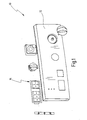
- Fig. 1 is an embodiment of the shutter arrangement according to the invention generally designated 10.
- the aperture arrangement 10 is provided for a household machine such as a washing machine or a tumble dryer and includes the service and Display elements for operating the household appliance or for Show their respective state.
- the diaphragm assembly 10 has a diaphragm 12, which as Plastic plate is formed with a circumferential edge.
- a diaphragm 12 which as Plastic plate is formed with a circumferential edge.
- front of the aperture 12 is with a high quality Surface provided to the household machine a to give high value.
- Two rotary switches are provided on the right side of the bezel.
- One of the rotary switches is designed for example a program of washing machine or tumble dryer select.
- Another rotary switch for example, the Selecting a certain spin speed or a certain one Temperature be formed.
- an unspecified display intended.
- the diaphragm assembly 10 includes a key arrangement, which is generally designated 14 in FIG.
- the button assembly 14 includes five buttons, which in two Groups are divided. One group contains three buttons and the other group contains two buttons. The two groups are spatially spaced from each other. Accordingly, in the Aperture 12 two differently sized cutouts for the key groups intended.
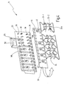
- Fig. 2 shows the aperture assembly 10 in an assembled Condition from the back.
- the key arrangement 14 has a key support 20.
- the Button support 20 is generally plate-shaped and is designed to a plurality of keys 22 to store.
- the keys 22 are on their front in Fig. 3 to see provided with a control surface 26. Point at the back the keys 22 each have four pin-like projections 24.
- the Buttons 22 are each formed approximately rectangular in plan view.
- the four projections 24 are approximately in the region of four Corners provided and project to the rear.
- the button carrier is generally elongated.
- a Row of openings 28 is provided along an upper edge.
- the other row of openings 28 is along the bottom Edge provided.
- the openings 28 are at a regular distance. The distance The openings 28 are selected so that two upper projections 24 a narrow button 22b in two adjacent openings 28 of a Fit opening row. In a similar way fit two lower Projections 24 of the same key 22b in two adjacent Openings 28 of the lower row.
- the distance of the projections 24 of the wider key 22a is so chosen to fit in two openings 28, the double Have distance. In other words, between the two openings 28 another (not used) opening 28th arranged.
- button projections 24 could have even greater distance.
- the shape of the control surface 26 is of the arrangement of the projections the respective keys 22 largely decoupled.
- the operating surface 26 is shaped so that it arching approximately convexly in cross section to the outside.
- the keys could also be oval or circular.
- the shape of the button to corresponding Cutouts in an associated aperture 12 adapted have to be.
- you can also use oval or circular buttons have four projections 24 which in the openings 28 of the button carrier 20 fit.
- the key support 20 is universally formed. Keys used in conjunction with this button carrier 20 only need to have four projections 24 whose spacing in the grid of the openings 28 of the button carrier 20th fits.
- the printed circuit board 30 is also approximately rectangular and has a height such that it is between the two opposite rows of openings 28 is arranged. With In other words, the printed circuit board 30 covers the openings 28 not from the back.
- the key assembly 14 further includes a number of key levers 32, for each key 22 an associated key lever 32nd
- the key levers 32 are at the back of the circuit board 30th intended.
- Each key lever 32 has a central portion and two opposite lever sections.
- One upper lever section is connected to the middle section via a Rotary axis 33-1 connected.
- a lower lever section is with connected to the central portion via another axis of rotation 33-2.
- the key levers 32 are in the region of the back of the circuit board 30 stored that lever sections behind the openings 28, through the projections 24 of the associated key 22 grab.
- the middle section is provided with return springs 34, which are supported on the back of the circuit board 30.
- return springs 34 which are supported on the back of the circuit board 30.
- hoods 36 are arranged from a resilient plastic material.
- the hoods 36 are in a two-component injection molding process produced together with the key support 20.
- the hoods 36 are closed and form a closed Recording for the respective projections 24.
- the length of the projections 24 and the hoods 36 are so coordinated, that the keys 22 generally due to the elasticity of the hoods 36 biased in a home position away from the key support 20 become.
- Fig. 3 it can be seen that the keys 22 at its upper and lower end each have a (unspecified) approach exhibit. This approach is in the installed state the back of a panel 12 at. This investment position is determined the rest position of the keys 22.
- a plurality of Locking projections 38 integrally formed on the back of the button carrier 20 .
- a plurality of slots 40 are arranged in the circuit board 30 . The position and size of the slots 40 corresponds to that of Latching projections 38.
- the circuit board is pressed onto the key support 20, that the locking projections 38 penetrate into the slots 40.
- the locking projections 38 have suitable locking means, so that the Circuit board 30 thereby detent fixed to the key support 20 becomes.
- the latching projections 38 are further adapted to the key levers 32 store. More specifically, the key levers 32 unspecified detent eyes on to the key lever 32 at the opposite to the back of the circuit board 30 above Locking projections 38 set.
- the locking projections serve here 38 at the same time as bearing points for setting up the axes of rotation 33-1 and 33-2.
- latching projections 38 For reasons of clarity, not all latching projections are shown in FIG. 4 38 shown. In general, however, it is preferable that the latching projections 38 parallel to the openings 28 two Form rows with equal distances.
- the wide button levers 32a is between two bearing points a cutout present to an unused locking projection 38 to record without contact.
- microswitch 42nd At the back of the circuit board 30 are microswitch 42nd arranged.
- the number of microswitches 42 corresponds to that the keys 22.
- the microswitches are in a middle area of the PCB 30, in each case between slots 40, which are associated with a button 22.
- the direction of actuation of the microswitch 42 is opposite to the direction of actuation of the keys 22.
- Fig. 5 shows a schematic cross-sectional view through the Button assembly 14 of Figures 3 and 4 installed in a state at a diaphragm 12 of a diaphragm arrangement 10.
- the key support 20 is fixed to the back of the aperture 12.
- the illustrated button 22 passes through an opening in the Aperture 12. Through one up and one down above approach will avoid that the button 22 after falls out at the front.
- the central portion of the button lever 32 is replaced by the return springs 34 back to its initial or basic position brought in which he does not actuate the micro-switch 42.
- the Return springs 34 are supported on the back of the PCB 30 from.
- Fig. 5 is shown schematically that the axes of rotation 33-1 and 33-2 through one opposite the back of the circuit board 30 protruding projection are stored, different from the Tab 38 of the button carrier 20 is different. It understands However, that the axes of rotation also directly to the locking projections 38 may be stored.
- At the front of the circuit board 30 may be for display purposes one or more LEDs can be arranged.
- one or more LEDs can be arranged.
- Micro switch 42 may be associated with a LED 44, the operating state thereof indicates.
- the key support 20 is preferably made of a transparent Material produced.
- the light emitted by the LED 44 thus falls on the back of the key 22.
- the button 22 has a central opening 48 into which a transparent insert 50 is clipped.
- the LED light 46 is from the front of the button 22 visible through the insert 50.
- the material of the key support 20 may be for example ABS.
- the buttons 22 can also without translucent insert (or. Light guide) 50 may be formed.
- Fig. 5 is further shown that the key support 20 at the Rear of the aperture 12 is attached via a line weld 60 is.
- the line weld 60 can, as shown in Fig. 5, only provided in an upper region of the key support 20 be. At the bottom, for example, welds be provided to achieve a good attachment.
- the projections 24 of the keys 22b are at a distance own a.
- the projections 24 are the wider Button 22a spaced by twice the value 2a.
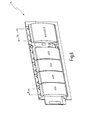
- Fig. 7 are also some variants of the invention Button arrangement shown.
- buttons are on the button support 20 only three extra wide buttons provided.
- the variant below corresponds to the arrangement of five buttons in two groups of Fig. 1. To the left is the variant of Figures 3 and 4 shown.
- FIG. 7 each show different ones Forming keys, for example with a circular projection or such buttons (on the right), preferably be operated at its lower end.
- the key support 20 is for receiving a maximum of six Buttons each with a width of about 17 mm designed.
Landscapes
- Push-Button Switches (AREA)
Priority Applications (1)
| Application Number | Priority Date | Filing Date | Title |
|---|---|---|---|
| PL04021401T PL1523022T3 (pl) | 2003-09-17 | 2004-09-09 | Układ przycisków do panelu obsługi |
Applications Claiming Priority (4)
| Application Number | Priority Date | Filing Date | Title |
|---|---|---|---|
| DE10344917 | 2003-09-17 | ||
| DE10344917 | 2003-09-17 | ||
| DE102004004247A DE102004004247A1 (de) | 2003-09-17 | 2004-01-21 | Tastenanordnung für eine Bedienblende |
| DE102004004247 | 2004-01-21 |
Publications (3)
| Publication Number | Publication Date |
|---|---|
| EP1523022A2 true EP1523022A2 (fr) | 2005-04-13 |
| EP1523022A3 EP1523022A3 (fr) | 2007-05-09 |
| EP1523022B1 EP1523022B1 (fr) | 2011-11-02 |
Family
ID=34314998
Family Applications (1)
| Application Number | Title | Priority Date | Filing Date |
|---|---|---|---|
| EP04021401A Expired - Lifetime EP1523022B1 (fr) | 2003-09-17 | 2004-09-09 | Assemblage de touches pour un panneau de commande |
Country Status (3)
| Country | Link |
|---|---|
| US (1) | US7041922B2 (fr) |
| EP (1) | EP1523022B1 (fr) |
| PL (1) | PL1523022T3 (fr) |
Cited By (3)
| Publication number | Priority date | Publication date | Assignee | Title |
|---|---|---|---|---|
| EP2051269A1 (fr) * | 2007-10-16 | 2009-04-22 | BSH Bosch und Siemens Hausgeräte GmbH | Dispositif de commande d'appareil ménager |
| DE102011013180A1 (de) | 2011-03-05 | 2012-09-06 | Volkswagen Ag | Bauteil für eine Tastenanordnung einer Bedienblende |
| CN103390518A (zh) * | 2012-05-11 | 2013-11-13 | 住友电装株式会社 | 具有指示器的车辆用内饰零件 |
Families Citing this family (18)
| Publication number | Priority date | Publication date | Assignee | Title |
|---|---|---|---|---|
| WO2006011704A2 (fr) * | 2004-07-27 | 2006-02-02 | Lg Electronics Inc. | Climatiseur |
| JP4367850B2 (ja) * | 2004-09-27 | 2009-11-18 | シチズン電子株式会社 | 照光式スイッチ |
| TW200642563A (en) * | 2005-05-16 | 2006-12-01 | Benq Corp | Electric device with switches having high precision |
| US7211759B2 (en) * | 2005-09-16 | 2007-05-01 | Zippy Technology Corp. | Switch coupling structure |
| US7222979B1 (en) * | 2005-11-09 | 2007-05-29 | Cfm Corporation | Illuminated dial |
| CN2874751Y (zh) * | 2006-01-13 | 2007-02-28 | 鸿富锦精密工业(深圳)有限公司 | 面板按键结构 |
| USD551175S1 (en) * | 2006-01-18 | 2007-09-18 | Metro Industries Inc. | Control panel module for a high humidity cabinet |
| DE102006013937A1 (de) * | 2006-03-16 | 2007-09-27 | Prettl Appliance Systems Gmbh | Bedienblendenanordnung für Haushaltsmaschinen und Verfahren zur Herstellung einer Bedienblendenanordnung |
| ES1063868Y (es) * | 2006-09-28 | 2007-03-16 | Simon Sa | Tecla basculante con visor luminoso y funda cromatica para accionamiento de mecanismos electricos |
| JP2009119916A (ja) * | 2007-11-12 | 2009-06-04 | Clarion Co Ltd | 画面部収納型機器及び車載用情報機器 |
| DE102009006434B3 (de) * | 2009-01-22 | 2010-06-17 | E.G.O. Elektro-Gerätebau GmbH | Bedieneinrichtung für ein Elektrogerät und Bedienblende |
| US8209868B2 (en) | 2009-07-27 | 2012-07-03 | The Gillette Company | Device with an illuminated button assembly |
| TWM381117U (en) * | 2010-01-08 | 2010-05-21 | Darfon Electronics Corp | Key and keyboard with low light dispersion |
| CN102403149B (zh) * | 2010-09-10 | 2014-03-26 | 富泰华工业(深圳)有限公司 | 按键结构及具有该按键结构的电子装置 |
| KR20120075794A (ko) * | 2010-12-29 | 2012-07-09 | 삼성전자주식회사 | 세탁기 |
| US8829376B2 (en) * | 2012-07-12 | 2014-09-09 | Paradigm Inc. | Control panel for fitness equipment |
| JP6394910B2 (ja) * | 2015-08-27 | 2018-09-26 | 京セラドキュメントソリューションズ株式会社 | キースイッチ装置及び画像形成装置 |
| JP7212850B2 (ja) * | 2020-12-09 | 2023-01-26 | カシオ計算機株式会社 | スイッチ装置及び、電子機器 |
Citations (1)
| Publication number | Priority date | Publication date | Assignee | Title |
|---|---|---|---|---|
| DE19817369A1 (de) | 1997-05-07 | 1998-11-12 | Marquardt Gmbh | Anordnung von Schaltern |
Family Cites Families (3)
| Publication number | Priority date | Publication date | Assignee | Title |
|---|---|---|---|---|
| DE3310313A1 (de) * | 1983-03-22 | 1984-09-27 | Sachsse Brigitte | Drucktaste |
| JPH0251169A (ja) * | 1988-08-12 | 1990-02-21 | Konica Corp | 複写機 |
| US5045656A (en) * | 1989-07-05 | 1991-09-03 | Idec Izumi Corporation | Switch provided with indicator |
-
2004
- 2004-09-09 PL PL04021401T patent/PL1523022T3/pl unknown
- 2004-09-09 EP EP04021401A patent/EP1523022B1/fr not_active Expired - Lifetime
- 2004-09-16 US US10/944,431 patent/US7041922B2/en not_active Expired - Lifetime
Patent Citations (1)
| Publication number | Priority date | Publication date | Assignee | Title |
|---|---|---|---|---|
| DE19817369A1 (de) | 1997-05-07 | 1998-11-12 | Marquardt Gmbh | Anordnung von Schaltern |
Cited By (5)
| Publication number | Priority date | Publication date | Assignee | Title |
|---|---|---|---|---|
| EP2051269A1 (fr) * | 2007-10-16 | 2009-04-22 | BSH Bosch und Siemens Hausgeräte GmbH | Dispositif de commande d'appareil ménager |
| WO2009050093A1 (fr) * | 2007-10-16 | 2009-04-23 | BSH Bosch und Siemens Hausgeräte GmbH | Dispositif de commande d'équipement ménager |
| DE102011013180A1 (de) | 2011-03-05 | 2012-09-06 | Volkswagen Ag | Bauteil für eine Tastenanordnung einer Bedienblende |
| CN103390518A (zh) * | 2012-05-11 | 2013-11-13 | 住友电装株式会社 | 具有指示器的车辆用内饰零件 |
| CN103390518B (zh) * | 2012-05-11 | 2015-08-19 | 住友电装株式会社 | 具有指示器的车辆用内饰零件 |
Also Published As
| Publication number | Publication date |
|---|---|
| EP1523022B1 (fr) | 2011-11-02 |
| US20050109592A1 (en) | 2005-05-26 |
| US7041922B2 (en) | 2006-05-09 |
| PL1523022T3 (pl) | 2012-04-30 |
| EP1523022A3 (fr) | 2007-05-09 |
Similar Documents
| Publication | Publication Date | Title |
|---|---|---|
| EP1523022B1 (fr) | Assemblage de touches pour un panneau de commande | |
| DE19537296C2 (de) | Wippenschaltvorrichtung für zweistufigen Betätigungshub | |
| EP0101092B1 (fr) | Dispositif pour l'entrée et/ou l'indication de données pour appareils électriques | |
| EP3213016B1 (fr) | Appareil ménager comportant un dispositif d'entrée et un système de codage | |
| EP0980577B1 (fr) | Ensemble de commutateurs | |
| EP2032755A1 (fr) | Unité de commande pour appareil ménager | |
| EP1176619B1 (fr) | Unité de commande électronique | |
| EP1662207B1 (fr) | Dispositiv de contrôle pour un appareil ménager | |
| DE60100322T2 (de) | Schaltvorrichtung und Verfahren zum Zusammenbau einer Schaltvorrichtung | |
| EP2206132A1 (fr) | Actionneur | |
| DE102010063014A1 (de) | Bedienfeld mit blendenartiger Ausbildung | |
| WO2011085940A1 (fr) | Dispositif de commande pour appareil ménager et appareil ménager comportant un dispositif de commande | |
| EP2199687A2 (fr) | Unité de commande pour un appareil ménager et appareil ménager | |
| DE102004004247A1 (de) | Tastenanordnung für eine Bedienblende | |
| EP2993959B1 (fr) | Appareil ménager | |
| EP1728026B2 (fr) | Bandeau de commande pour un appareil de refrigeration domestique | |
| EP4025111B1 (fr) | Lave-vaisselle domestique | |
| DE19739575C2 (de) | Funktionsblock, insbesondere Tastenblock, für die Bedienfläche eines Geräts sowie Bedienfläche eines Geräts mit einem derartigen Funktionsblock | |
| DE10309516B3 (de) | Tastenblock mit Federgeometrie | |
| EP1545177A1 (fr) | Cadre de centrage | |
| DE3034540C2 (de) | Druckknopfschalter | |
| DE102009010739B4 (de) | Tastenanordnung und Waschmaschine mit dieser | |
| DE10141635B4 (de) | Frontblende mit einem Griffelement für Haushaltgerät | |
| DE3100053C2 (de) | Tastatur zur Bedienung der elektronischen Steuerung einer Kunststoff-Spritzgießmaschine | |
| DE8132410U1 (de) | Elektrischer Miniaturschalter |
Legal Events
| Date | Code | Title | Description |
|---|---|---|---|
| PUAI | Public reference made under article 153(3) epc to a published international application that has entered the european phase |
Free format text: ORIGINAL CODE: 0009012 |
|
| AK | Designated contracting states |
Kind code of ref document: A2 Designated state(s): AT BE BG CH CY CZ DE DK EE ES FI FR GB GR HU IE IT LI LU MC NL PL PT RO SE SI SK TR |
|
| AX | Request for extension of the european patent |
Extension state: AL HR LT LV MK |
|
| RAP1 | Party data changed (applicant data changed or rights of an application transferred) |
Owner name: PRETTL APPLIANCE SYSTEMS GMBH |
|
| PUAL | Search report despatched |
Free format text: ORIGINAL CODE: 0009013 |
|
| AK | Designated contracting states |
Kind code of ref document: A3 Designated state(s): AT BE BG CH CY CZ DE DK EE ES FI FR GB GR HU IE IT LI LU MC NL PL PT RO SE SI SK TR |
|
| AX | Request for extension of the european patent |
Extension state: AL HR LT LV MK |
|
| 17P | Request for examination filed |
Effective date: 20070905 |
|
| AKX | Designation fees paid |
Designated state(s): AT BE BG CH CY CZ DE DK EE ES FI FR GB GR HU IE IT LI LU MC NL PL PT RO SE SI SK TR |
|
| 17Q | First examination report despatched |
Effective date: 20090216 |
|
| RAP1 | Party data changed (applicant data changed or rights of an application transferred) |
Owner name: PAS DEUTSCHLAND GMBH |
|
| GRAP | Despatch of communication of intention to grant a patent |
Free format text: ORIGINAL CODE: EPIDOSNIGR1 |
|
| GRAS | Grant fee paid |
Free format text: ORIGINAL CODE: EPIDOSNIGR3 |
|
| GRAA | (expected) grant |
Free format text: ORIGINAL CODE: 0009210 |
|
| AK | Designated contracting states |
Kind code of ref document: B1 Designated state(s): AT BE BG CH CY CZ DE DK EE ES FI FR GB GR HU IE IT LI LU MC NL PL PT RO SE SI SK TR |
|
| REG | Reference to a national code |
Ref country code: GB Ref legal event code: FG4D Free format text: NOT ENGLISH |
|
| REG | Reference to a national code |
Ref country code: CH Ref legal event code: EP |
|
| REG | Reference to a national code |
Ref country code: IE Ref legal event code: FG4D |
|
| REG | Reference to a national code |
Ref country code: DE Ref legal event code: R096 Ref document number: 502004013019 Country of ref document: DE Effective date: 20120112 |
|
| REG | Reference to a national code |
Ref country code: NL Ref legal event code: VDEP Effective date: 20111102 |
|
| REG | Reference to a national code |
Ref country code: ES Ref legal event code: FG2A Ref document number: 2376752 Country of ref document: ES Kind code of ref document: T3 Effective date: 20120316 |
|
| REG | Reference to a national code |
Ref country code: PL Ref legal event code: T3 |
|
| PG25 | Lapsed in a contracting state [announced via postgrant information from national office to epo] |
Ref country code: SE Free format text: LAPSE BECAUSE OF FAILURE TO SUBMIT A TRANSLATION OF THE DESCRIPTION OR TO PAY THE FEE WITHIN THE PRESCRIBED TIME-LIMIT Effective date: 20111102 Ref country code: GR Free format text: LAPSE BECAUSE OF FAILURE TO SUBMIT A TRANSLATION OF THE DESCRIPTION OR TO PAY THE FEE WITHIN THE PRESCRIBED TIME-LIMIT Effective date: 20120203 Ref country code: NL Free format text: LAPSE BECAUSE OF FAILURE TO SUBMIT A TRANSLATION OF THE DESCRIPTION OR TO PAY THE FEE WITHIN THE PRESCRIBED TIME-LIMIT Effective date: 20111102 Ref country code: PT Free format text: LAPSE BECAUSE OF FAILURE TO SUBMIT A TRANSLATION OF THE DESCRIPTION OR TO PAY THE FEE WITHIN THE PRESCRIBED TIME-LIMIT Effective date: 20120302 Ref country code: SI Free format text: LAPSE BECAUSE OF FAILURE TO SUBMIT A TRANSLATION OF THE DESCRIPTION OR TO PAY THE FEE WITHIN THE PRESCRIBED TIME-LIMIT Effective date: 20111102 |
|
| REG | Reference to a national code |
Ref country code: IE Ref legal event code: FD4D |
|
| PG25 | Lapsed in a contracting state [announced via postgrant information from national office to epo] |
Ref country code: CY Free format text: LAPSE BECAUSE OF FAILURE TO SUBMIT A TRANSLATION OF THE DESCRIPTION OR TO PAY THE FEE WITHIN THE PRESCRIBED TIME-LIMIT Effective date: 20111102 |
|
| PG25 | Lapsed in a contracting state [announced via postgrant information from national office to epo] |
Ref country code: DK Free format text: LAPSE BECAUSE OF FAILURE TO SUBMIT A TRANSLATION OF THE DESCRIPTION OR TO PAY THE FEE WITHIN THE PRESCRIBED TIME-LIMIT Effective date: 20111102 Ref country code: BG Free format text: LAPSE BECAUSE OF FAILURE TO SUBMIT A TRANSLATION OF THE DESCRIPTION OR TO PAY THE FEE WITHIN THE PRESCRIBED TIME-LIMIT Effective date: 20120202 Ref country code: IE Free format text: LAPSE BECAUSE OF FAILURE TO SUBMIT A TRANSLATION OF THE DESCRIPTION OR TO PAY THE FEE WITHIN THE PRESCRIBED TIME-LIMIT Effective date: 20111102 Ref country code: EE Free format text: LAPSE BECAUSE OF FAILURE TO SUBMIT A TRANSLATION OF THE DESCRIPTION OR TO PAY THE FEE WITHIN THE PRESCRIBED TIME-LIMIT Effective date: 20111102 Ref country code: SK Free format text: LAPSE BECAUSE OF FAILURE TO SUBMIT A TRANSLATION OF THE DESCRIPTION OR TO PAY THE FEE WITHIN THE PRESCRIBED TIME-LIMIT Effective date: 20111102 |
|
| PG25 | Lapsed in a contracting state [announced via postgrant information from national office to epo] |
Ref country code: IT Free format text: LAPSE BECAUSE OF FAILURE TO SUBMIT A TRANSLATION OF THE DESCRIPTION OR TO PAY THE FEE WITHIN THE PRESCRIBED TIME-LIMIT Effective date: 20111102 Ref country code: RO Free format text: LAPSE BECAUSE OF FAILURE TO SUBMIT A TRANSLATION OF THE DESCRIPTION OR TO PAY THE FEE WITHIN THE PRESCRIBED TIME-LIMIT Effective date: 20111102 |
|
| PLBE | No opposition filed within time limit |
Free format text: ORIGINAL CODE: 0009261 |
|
| STAA | Information on the status of an ep patent application or granted ep patent |
Free format text: STATUS: NO OPPOSITION FILED WITHIN TIME LIMIT |
|
| 26N | No opposition filed |
Effective date: 20120803 |
|
| REG | Reference to a national code |
Ref country code: DE Ref legal event code: R097 Ref document number: 502004013019 Country of ref document: DE Effective date: 20120803 |
|
| BERE | Be: lapsed |
Owner name: PAS DEUTSCHLAND G.M.B.H. Effective date: 20120930 |
|
| PG25 | Lapsed in a contracting state [announced via postgrant information from national office to epo] |
Ref country code: MC Free format text: LAPSE BECAUSE OF NON-PAYMENT OF DUE FEES Effective date: 20120930 |
|
| REG | Reference to a national code |
Ref country code: CH Ref legal event code: PL |
|
| GBPC | Gb: european patent ceased through non-payment of renewal fee |
Effective date: 20120909 |
|
| PG25 | Lapsed in a contracting state [announced via postgrant information from national office to epo] |
Ref country code: FI Free format text: LAPSE BECAUSE OF FAILURE TO SUBMIT A TRANSLATION OF THE DESCRIPTION OR TO PAY THE FEE WITHIN THE PRESCRIBED TIME-LIMIT Effective date: 20111102 |
|
| REG | Reference to a national code |
Ref country code: FR Ref legal event code: ST Effective date: 20130531 |
|
| PG25 | Lapsed in a contracting state [announced via postgrant information from national office to epo] |
Ref country code: LI Free format text: LAPSE BECAUSE OF NON-PAYMENT OF DUE FEES Effective date: 20120930 Ref country code: CH Free format text: LAPSE BECAUSE OF NON-PAYMENT OF DUE FEES Effective date: 20120930 Ref country code: BE Free format text: LAPSE BECAUSE OF NON-PAYMENT OF DUE FEES Effective date: 20120930 Ref country code: GB Free format text: LAPSE BECAUSE OF NON-PAYMENT OF DUE FEES Effective date: 20120909 |
|
| PG25 | Lapsed in a contracting state [announced via postgrant information from national office to epo] |
Ref country code: FR Free format text: LAPSE BECAUSE OF NON-PAYMENT OF DUE FEES Effective date: 20121001 |
|
| REG | Reference to a national code |
Ref country code: AT Ref legal event code: MM01 Ref document number: 532196 Country of ref document: AT Kind code of ref document: T Effective date: 20120909 |
|
| PG25 | Lapsed in a contracting state [announced via postgrant information from national office to epo] |
Ref country code: AT Free format text: LAPSE BECAUSE OF NON-PAYMENT OF DUE FEES Effective date: 20120909 |
|
| PG25 | Lapsed in a contracting state [announced via postgrant information from national office to epo] |
Ref country code: LU Free format text: LAPSE BECAUSE OF NON-PAYMENT OF DUE FEES Effective date: 20120909 |
|
| PG25 | Lapsed in a contracting state [announced via postgrant information from national office to epo] |
Ref country code: HU Free format text: LAPSE BECAUSE OF FAILURE TO SUBMIT A TRANSLATION OF THE DESCRIPTION OR TO PAY THE FEE WITHIN THE PRESCRIBED TIME-LIMIT Effective date: 20040909 |
|
| PGFP | Annual fee paid to national office [announced via postgrant information from national office to epo] |
Ref country code: CZ Payment date: 20170908 Year of fee payment: 14 |
|
| PGFP | Annual fee paid to national office [announced via postgrant information from national office to epo] |
Ref country code: TR Payment date: 20170907 Year of fee payment: 14 Ref country code: PL Payment date: 20170822 Year of fee payment: 14 |
|
| PGFP | Annual fee paid to national office [announced via postgrant information from national office to epo] |
Ref country code: DE Payment date: 20171025 Year of fee payment: 14 |
|
| PGFP | Annual fee paid to national office [announced via postgrant information from national office to epo] |
Ref country code: ES Payment date: 20171026 Year of fee payment: 14 |
|
| REG | Reference to a national code |
Ref country code: DE Ref legal event code: R119 Ref document number: 502004013019 Country of ref document: DE |
|
| PG25 | Lapsed in a contracting state [announced via postgrant information from national office to epo] |
Ref country code: CZ Free format text: LAPSE BECAUSE OF NON-PAYMENT OF DUE FEES Effective date: 20180909 |
|
| PG25 | Lapsed in a contracting state [announced via postgrant information from national office to epo] |
Ref country code: DE Free format text: LAPSE BECAUSE OF NON-PAYMENT OF DUE FEES Effective date: 20190402 |
|
| REG | Reference to a national code |
Ref country code: ES Ref legal event code: FD2A Effective date: 20191030 |
|
| PG25 | Lapsed in a contracting state [announced via postgrant information from national office to epo] |
Ref country code: ES Free format text: LAPSE BECAUSE OF NON-PAYMENT OF DUE FEES Effective date: 20180910 Ref country code: PL Free format text: LAPSE BECAUSE OF NON-PAYMENT OF DUE FEES Effective date: 20180909 |
|
| PG25 | Lapsed in a contracting state [announced via postgrant information from national office to epo] |
Ref country code: TR Free format text: LAPSE BECAUSE OF NON-PAYMENT OF DUE FEES Effective date: 20180909 |