EP2051269A1 - Dispositif de commande d'appareil ménager - Google Patents
Dispositif de commande d'appareil ménager Download PDFInfo
- Publication number
- EP2051269A1 EP2051269A1 EP08104483A EP08104483A EP2051269A1 EP 2051269 A1 EP2051269 A1 EP 2051269A1 EP 08104483 A EP08104483 A EP 08104483A EP 08104483 A EP08104483 A EP 08104483A EP 2051269 A1 EP2051269 A1 EP 2051269A1
- Authority
- EP
- European Patent Office
- Prior art keywords
- operating
- domestic appliance
- areas
- area
- operating means
- Prior art date
- Legal status (The legal status is an assumption and is not a legal conclusion. Google has not performed a legal analysis and makes no representation as to the accuracy of the status listed.)
- Withdrawn
Links
Images






Classifications
-
- H—ELECTRICITY
- H01—ELECTRIC ELEMENTS
- H01H—ELECTRIC SWITCHES; RELAYS; SELECTORS; EMERGENCY PROTECTIVE DEVICES
- H01H13/00—Switches having rectilinearly-movable operating part or parts adapted for pushing or pulling in one direction only, e.g. push-button switch
- H01H13/70—Switches having rectilinearly-movable operating part or parts adapted for pushing or pulling in one direction only, e.g. push-button switch having a plurality of operating members associated with different sets of contacts, e.g. keyboard
- H01H13/702—Switches having rectilinearly-movable operating part or parts adapted for pushing or pulling in one direction only, e.g. push-button switch having a plurality of operating members associated with different sets of contacts, e.g. keyboard with contacts carried by or formed from layers in a multilayer structure, e.g. membrane switches
- H01H13/705—Switches having rectilinearly-movable operating part or parts adapted for pushing or pulling in one direction only, e.g. push-button switch having a plurality of operating members associated with different sets of contacts, e.g. keyboard with contacts carried by or formed from layers in a multilayer structure, e.g. membrane switches characterised by construction, mounting or arrangement of operating parts, e.g. push-buttons or keys
-
- H—ELECTRICITY
- H01—ELECTRIC ELEMENTS
- H01H—ELECTRIC SWITCHES; RELAYS; SELECTORS; EMERGENCY PROTECTIVE DEVICES
- H01H2231/00—Applications
- H01H2231/012—Household appliance
Definitions
- the invention relates to a domestic appliance operating device with at least one operating means guiding unit, to which a plurality of operating means of the same operating mode are attached, as well as such a domestic appliance.
- EP1 545 177 B1 discloses an assembly comprising: a housing part, a printed circuit board covered by the housing part, and a centering frame inserted between the housing part and the printed circuit board for centering at least one operating means which establishes an operating connection between a first operating element on the housing part and a second operating element on the printed circuit board wherein the at least one operating means is fixedly connected to the housing part or to the circuit board.
- the centering frame may comprise a substantially circular aperture. This is suitable for a pestle.
- the plunger is mounted on an on / off switch, which in turn is arranged on the front side of a printed circuit board.
- microswitches are mounted side by side on the printed circuit board, each with a push-button.
- the buttons are actuated by the plungers.
- other components can be arranged on the circuit board, such as LEDs.
- DE 19810438 A1 discloses a cooker with four cooking zones and a baking and roasting oven.
- the stove comprises a control panel with four arranged in the form of a matrix rotary knobs for operating the hob and with an operating device for operating the oven and roasting oven.
- an operating device for operating the oven and roasting oven.
- the pushbuttons can be split into a bottom row of seven lower pushbuttons and a top row with only two larger pushbuttons.
- the object is achieved by means of a domestic appliance operating device for a domestic appliance and by means of a household appliance according to the features of the respective independent claim.
- the operating means can be at least subdivided into at least one first set with at least one operating means of a first operating mode and at least one second set with two or more operating elements of a second operating mode.
- control operating means Under operating elements of the same type of control operating means are understood that are operated or operated by a user in a fundamentally the same way.
- the underlying contact principle mechanical, piezoelectric, capacitive, electronic, optical, etc.
- the geometric arrangement is initially irrelevant.
- At least the operating means of the second set have operating areas with a different geometric shape.
- the operating modes are selected from the group comprising rotary actuators and push buttons as belonging to different operating modes. While turntables are operated by rotation, push-buttons are operated by a pushing movement.
- Push-buttons comprise switches and buttons (including toggle switches, slide switches, push-buttons, rocker switches and sensor buttons).
- the domestic appliance operating device may then have at least one first set of operating means, which comprises a turntable, and a second set of operating means, which comprises at least two push-buttons.
- at least two of the push-button on operating areas with different geometric shape. So may have two short-stroke keys operating areas with different geometric shape.
- a short-stroke key and a sensor keys can have operating areas with different geometric shapes.
- the operating modes are selected from the group comprising, firstly, turntables, secondly, push-buttons and push-buttons, and third, sensor buttons as belonging to different operating modes.
- the home appliance operating device may have at least one first set of operating means, which comprises a turntable, and a second set of operating means, which comprises at least two push-buttons and buttons or at least two touch buttons.
- actuating elements that can be moved when actuated and, when actuated, essentially immobile operating means (sensor keys).
- at least the push-button switches and buttons or the sensor keys have operating areas with a different geometric shape. So may have two short-stroke keys operating areas with different geometric shape.
- the domestic appliance operating device can then also have a push-button switch or push-button, as well as operating means of the second set of several sensor keys with at least partially different geometric configuration of the operating area.
- the operating modes are selected from the group comprising rotary switches, push switches, push buttons and sensor buttons as belonging to different operating modes.
- the home appliance operating device may comprise at least a first set of operating means comprising a turntable or a push switch (eg, stroke switch or toggle switch) as well as a second set of operating means comprising at least two buttons (push or touch keys).
- At least the keys have operating areas with a different geometric shape.
- at least two short-stroke keys may have operating areas with a different geometric shape.
- Sensor keys of such a set then include, for example, each reverb buttons, capacitive buttons or piezo keys.
- a domestic appliance operating device with at least one turntable and a plurality of short-stroke keys, of which have at least two differently configured operating areas.
- the domestic appliance operating device can also comprise a plurality of operating means of the first operating mode and a plurality of operating elements of a second operating mode, wherein in one variant only the operating means of the second set have operating areas with a different geometric shape.
- operating means of the first and the second set can have operating areas, each with a different geometric shape.
- the home appliance operating device one or more additional sets of operating means each have the same operating mode.
- At least two of the operating means of a common set have operating areas with different shapes.
- an operating means guiding unit may be preferred in which at least two of the operating means of a common set have operating areas of different sizes, namely with the same or different shape.
- control means of a common set which are provided with operating areas of different geometric shape, are arranged in a common receiving area of the operating means guiding unit. This is understood in other words that these operating means are not arranged separately from each other, but are bordered by a common operating means bank or guide frame.
- operating means with operating areas of the same geometric shape of a common set with operating areas different geometric shape are arranged in a common receiving area.
- a common receiving area preferably only operating means with operating areas of the same geometric shape are combined and operating means of this same set are arranged in a different receiving area, possibly together in a key-board.
- the operating means of the second set are designed as push-buttons or buttons, in particular as lifting buttons.
- an embodiment as so-called “aviator” in which the operating means of the second set are arranged in at least two groups laterally relative to the at least one operating means of the first set.
- the at least one operating means of the first set is designed in particular as a single turntable.
- the operating means of the second set are preferably symmetrical at positions, in particular mirror-symmetrical, arranged to the turntable.
- the household appliance is equipped with a control panel, wherein the household appliance operating device is arranged on the control panel, preferably by Moontage from behind.
- the control panel is provided with recesses for carrying out operating means, which correspond to receiving areas for the operating means of the domestic appliance operating device.
- a single recess may be provided in the control panel for a plurality of operating means, which are arranged on the domestic appliance operating device in a common key bed.
- the domestic appliance operating device provides a common housing or guide housing for the associated control means.
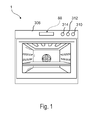
- Fig.1 shows a trained as an oven domestic appliance 1 with the domestic appliance operating device 88, which is arranged on a control panel 308 of the domestic appliance.
- the home appliance operating device 88 has been separately constructed and then married as a unit to the control panel 308.
- the control panel 308 may also have other, individually manufactured and with the control panel 308 married control means 310, 312, 314, z. B. comprising an on / off switch. Not shown, but may be present a display unit.
- Fig. 2 shows a three-dimensional view of the domestic appliance operating device 88 of the in Fig. 1 shown domestic appliance 1.
- Fig. 3 shows a front view of the domestic appliance operating device 88 without the operating means 24, 56, 58, 60, 62 and without the lighting unit 38th
- the household appliance operating device 88 comprises two halves, which are mirror-symmetrical to one another with respect to a mirror plane 52.
- the mirror plane 52 is perpendicular to a main extension direction 54 of the domestic appliance operating device 88. In the following, only one of the halves will be described, unless otherwise stated.
- the household appliance operating device 88 comprises operating means 24, 56, 58, 60, 62 and an operating means guiding unit 10 which has identically formed light guiding means 12, 28, 46, 48, 50.
- the operating means 24, 56, 58, 60, 62 designed as buttons are fastened to the operating means guiding unit 10 and are intended to be pressed in by an operator during an operating procedure.
- the operating means guiding unit 10 has a receiving area 66 (FIG. Fig. 3 ), which is bounded on its upper side 68 and on its underside 70 by guide surfaces 72, 74.
- the lower guide surface 74 is rectangular in shape and guides the operating means 24, 56, 58, 60, 62 in a depression.
- the guide surface 74 supports the operating means 24, 56, 58, 60, 62 in the vertical direction from the bottom.
- the guide surface 74 opposite the guide surface 72, which is formed by the undersides of the light guide means 12, 28, 46, 48, 50.
- an upper side of the operating means 24, 56, 58, 60, 62 moves along the guide surface 72, the upper side contacting the guide surface 72.
- the guide surface 72 leads in this way the operating means 24, 56, 58, 60, 62.
- the description is limited to the functionality of the operating means 24, wherein it also applies to the further operating means 56, 58, 60, 62 application.
- the domestic appliance operating device 88 has an operating means guide unit holder 34, which is formed integrally with the operating means guide unit 10 and carries it. Furthermore, the operating means guide unit holder 34 and the operating means guide unit 10 are sprayed during their production in a common injection molding process of polycarbonate.
- the operating means guide unit holder 34 has locking means designed as a latching hook 36, which are engaged in recesses of a lighting and sensor unit 38, 40 in an assembled state.
- the sensor unit 40 has a sensor 76, which is provided to register an impression of the operating means 24.
- the lighting unit 38 comprises a light-emitting means designed as a light-emitting diode 14.
- the light-emitting means 14 is received in a receiving area 16 of the light guide means 12 and projects into this.
- the light guiding means 12 comprises a region which, in a plan view from above, has the shape of a triangle with a concavely rounded corner. The concave rounded corner forms the receiving area 16.
- the light guide means 12 has the shape of a straight cylinder, wherein the triangular area forms part of the top surface of the cylinder. Two sides of the triangle adjoining the receiving region 16 extend in light emission directions 20, 22 of the luminous means 14.
- the light guide means 12 continues in a cuboid region. This side of the triangle is identical to one side of the rectangle.
- the cuboid has a visible in a front view of the domestic appliance operating device 88 side, which forms a visible surface 26.
- the light-guiding means 12 forwards the light to the visible surface 26 and thus marks the operating means 24 arranged therebelow.
- a surface 92 of the cuboid between the visible surface 26 and the side of the triangle is raised formed, which extends from the cuboid in the vertical direction upwards.
- the survey 92 also has the shape of a cuboid.
- the light guide means 28 is arranged, which is designed in one piece with the light guide means 12. Between a part of the cuboid of the light guide means 12 and a part of the cuboid of the light guide means 28, a space formed as an air gap is arranged, which forms a shielding means 30.
- the space is invisible in a front view of the Whyffenzhouaku 10. It prevents light emitted by the luminous means 14 from propagating into the adjacent light guide means 28, which prevents unintentional marking of the operating means 58.
- the operating means 24 On a front side, the operating means 24 has an operating region 78 which can be touched by a user in an assembled state and which is formed by a main body 84 of the operating means 24.
- an extension is formed on the back, which is formed by a locking lug 64.
- the latching lug 64 is engaged in the assembled state in the latching means 32 of the Whyschzhouech 10 and serves as a plunger, which actuates the sensor 76 when pressed.
- Fig. 4A shows the domestic appliance operating device 88 of the previous figures from the front, wherein the recorded from a common receiving area 66 control means 24,56,58,60,62 and a navigation control means 94 have a same structure, namely are designed as a push button in the form of identical Kurzhubtasten.
- the navigation control means 94 which can serve in particular together with the central rotary actuator 96 for the menu guidance of the domestic appliance, is arranged only separately from the other keys 24, 56, 58, 60, 62.
- the operating areas 78 of the short-stroke keys 24, 56, 58, 60, 62, 94 have the same geometric shape with regard to shape and size on, namely in front view rectangular outer contour.
- Only a central turntable 96 has a round outer contour of its operating region 98 which is round in front view.
- the operating means 24, 56, 58, 60, 64, 94, 96 are subdivided into a first set of operating means with a single turntable 96 and into a second set of operating means with a plurality of short-stroke keys 24, 56, 58, 60, 62 , 94th
- Fig. 4B shows the home appliance control device 88 in one for better clarity Fig. 4A similar view in a simplified, schematic representation. Illustrated by the household appliance operating device 88 is the only control means guide unit 10 with the operating means 24,56,58,60,62,94,96 and the associated receiving areas 66 (for the operating means 24,56,58,60,62), 98 (for the operating means 94) and 99 (for the operating means 96). Of the control means 24,56,58,60,62,94,96 only the operating area 78 or 98 are visible in front view.
- Fig. 5A shows a home appliance control device 100 according to the invention, in which now in contrast to the home appliance control device 88 off 4B the Kurzhubtasten 94,102 have operating areas 78,104 with different geometric shape.
- the operating area 78 of the navigation key 94 is unchanged elongated rectangular designed, while in a common receiving area 106 laterally juxtaposed Kurzhubtasten 102 have a laterally shortened in front view, namely square shape while having a smaller area.
- the navigation key 94 is emphasized, whereby, for example, menu navigation is more user-friendly.
- Fig. 5B shows a further embodiment according to the invention a home appliance operating device 108, in which now in contrast to the embodiment according to Fig. 5A in a common receiving area 110
- Kurzhubtasten 60,62,102 are recorded with differently designed operating areas 78 and 104 respectively.
- the short-stroke keys 60,62 with the larger Operating area 78 are stressed, z. B., to more strongly indicate frequently used keys.
- Fig. 6 shows a further embodiment according to the invention a home appliance operating device 112, in which now in contrast to the embodiment according to Fig. 5A the plurality of short-stroke keys 116 received in a common receiving area (guide frame) 114 are inclined, so that the respective operating area 118 is diamond-shaped. Thus, a change in shape is also caused by a change in orientation.
- Fig. 7A shows a further embodiment of a home appliance operating device 120 according to the invention, in which now the plurality of recorded in a common receiving area 122 Kurzhubtasten 124 have a round operating area 126.
- the receiving area 122 is likewise no longer rectangular. As a result, a different function of the navigation key 94 and the other short-stroke keys 124 can be emphasized even more.
- FIG. 12 shows another embodiment of a home appliance control device 128 according to the invention, which includes the same buttons 94, 124 as in FIG Fig. 7A but which are now included in a common receiving area 130.
- the navigation key 94 is thereby closer to the other short-stroke keys 124. All keys are received in a common receiving area 130.
- Fig. 7C 8 shows yet another embodiment of a domestic appliance operating device 132 according to the invention, in which the keys 60, 62, 94, 124 are now divided into three receiving areas 98, 134, 136, namely the navigation key 94 individually in a receiving area 98, two keys 60, 62 with an angular operating area 78 identical to the navigation key 94 arranged side by side as a key bank in a common receiving area 134 and outermost three keys 124 with round operating area 126 as a key bank in a common receiving area 136.
- respective receiving areas 98,134,136 can be emphasized more a cohesion of key groups or their assigned functions.
- FIG. 8A shows yet another embodiment according to the invention a home appliance control device 138, in which now in contrast to the embodiment according to Fig. 7A also the navigation key 140 has a round operating area 142.
- a gradation is achieved in this case firstly by the size of the operating areas 98,126,142 and by the spatial summary in the respective receiving area 122,144.
- Fig. 8B shows yet another embodiment according to the invention a home appliance operating device 146, in which now in contrast to the embodiment according to Fig. 8A first, the keys 150,154,158,162,166 are recorded as a key bank in a common receiving area 148 and further the keys 150,154,158,162,166 from inside (near the turntable 96) to the outside operating range 152,156,160,164 and 168 have the same basic shape but graduated size.
- the innermost key 150 may be used, for example, as a navigation key, or have another function.
- Fig. 9A 1 shows a further embodiment according to the invention of a domestic appliance operating device 170, in which the inside button 172 now has a rectangular operating area 174 with a likewise shaped receiving area 176, while the outside key bench has in the common receiving area 178 five buttons 180, 184 with operating areas 182, 186 alternately shaped differently, namely alternating angular (diamond-shaped) operating areas 182 and round operating areas 186.
- the domestic appliance operating device 170 thus has buttons 172, 180, 184 with three basically differently shaped operating areas 174, 182, 186.
- Fig. 9B shows a further embodiment of a home appliance operating device 188 according to the invention, in which a key bank arranged directly next to the turntable 96 has a common receiving area 190 with three buttons 192, 96, 200, which respectively have operating areas 194, 198, 202 formed differently from each other.
- Fig. 10A shows yet another embodiment of a home appliance control device 204 similar to that of the present invention Fig. 8A , wherein now side of the turntable 96, a common receiving area 206 is arranged with five laterally adjacent keys 208,212,216,220,224 whose height increases from outside to inside. While the operating areas 214,218,222,226 of the outer four keys 212,216,220,224 have an angular outer contour with straight sides, a side of the operating area 210 of the innermost key 208 opposite the turntable 96 is curved to match the curvature of the outer contour of the turntable 96.
- Fig. 10B shows yet another embodiment of a home appliance control device 228 according to the invention similar to that Fig. 10A which in front view left of the turntable 94 the same receiving area 206 with the same buttons 208,212,216,220,224 as in Fig. 10A having.
- this embodiment is no longer mirror-symmetrical with respect to the mirror plane 52. Rather, it has in front view right of the turntable 94 a receiving area 230 with five laterally adjacent keys 232,236,240,244,248 whose height increases from inside to outside.
- the outer contours of the operating areas 210,214,218,222,226 of the buttons 208,212,216,220,224, the outer contour of the operating area 98 of the turntable 96 and the outer contours of the operating areas 234,238,242,246,250 of the keys 232,236,240,244,248 lie above and below each on a rising from the left to the right or descending line.
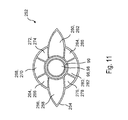
- Fig. 11 shows a further embodiment according to the invention a home appliance control device 252, in which the turntable 96 is now completely surrounded by a receiving area 254 for keys 256,260,264,268,272,276,280,284.
- Recorded in the receiving area 254 are two buttons 256,260 arranged on both sides of the turntable 96 with outwardly tapering operating areas 258,262, and additionally three keys 264,268,272 and 276,280,284 with ring-shaped control areas 266,270,274,278,282,286, respectively, annularly above and below.
- the operating areas 258,262,266,270,274,278,282,286 are curved on its side opposite the turntable 96 side whose shape is adjusted accordingly.
- FIG. 12 shows a similar embodiment of a home appliance control device 288 according to another embodiment of the invention Fig. 4B in which, however, the outer contour of the operating areas 78, 292 of the keys 56, 58, 24 and 290 does not differ, but rather their contour in cross-sectional view, as more precisely in FIG Figs. 13A to 13C is described.
- the operating regions 292 differ from the operating regions 78 by their height contour.
- the inner three keys 290 of which the innermost is received in a separate receiving area 294 and z. B. can serve as a navigation key, provided with a roof-shaped operating area 292, while the three outer buttons 56,58,24 have a rectangular operating area 78.
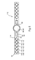
- Fig. 13A shows a sectional view in cross-sectional view of the operating means guide unit 10 Fig. 4B the operating area 78, which protrudes forward (here: on the left), of the button 56, which can be pressed to the right, the operating area 78 is cuboid out of the operating means guide unit 10 and is typically actuated by pressing the front operating surface 298 of the operating area 78.
- Fig. 13B shows a sectional view in cross-sectional view through a roof-shaped key 290 from Fig. 12 similar to the presentation Fig. 13A an operating-means guiding unit 10 with the operating area 292 protruding from the front side of the pushbutton 290 which can be pressed to the right.
- FIG. 13C as a sectional view in cross-sectional view in illustration similar to Fig. 13A an operating means guide unit 10 with a front side cuboid protruding operating portion 302 of the pressing to the right button 300, in which a front-side actuating surface 304 in contrast to the embodiment according to Fig. 13A the operating portion 302 has a forwardly extending semicircular protrusion 306 for improved feelability.
- a single turntable and a plurality of turntable with possibly geometrically differently ausgestaltetem operating area be attached to the home appliance control device.
- a switch can be used, for. As an on / off switch. It is also possible to use other keys or touch keys instead of the described short-stroke keys.
- the function of the operating means is not limited; so none of the control means for navigation through a control menu needs to be provided. Further, for example, switches and buttons can be arranged together and equal, z. In a common key bed; then the operating areas of the switch z. B. have a different from the operating areas of the keys geometric design. Egg home appliance may include a plurality of such home appliance operating device.
- the navigation controls can also be arranged above or below the turntable, in particular arranged with the other control means laterally of the turntable
Landscapes
- Push-Button Switches (AREA)
- Switches With Compound Operations (AREA)
- Switch Cases, Indication, And Locking (AREA)
- Planar Illumination Modules (AREA)
Priority Applications (2)
| Application Number | Priority Date | Filing Date | Title |
|---|---|---|---|
| EP08839927A EP2203926A1 (fr) | 2007-10-16 | 2008-10-09 | Dispositif de commande d'équipement ménager |
| PCT/EP2008/063505 WO2009050093A1 (fr) | 2007-10-16 | 2008-10-09 | Dispositif de commande d'équipement ménager |
Applications Claiming Priority (1)
| Application Number | Priority Date | Filing Date | Title |
|---|---|---|---|
| DE200710049571 DE102007049571A1 (de) | 2007-10-16 | 2007-10-16 | Hausgerätbedienvorrichtung |
Publications (1)
| Publication Number | Publication Date |
|---|---|
| EP2051269A1 true EP2051269A1 (fr) | 2009-04-22 |
Family
ID=40218535
Family Applications (3)
| Application Number | Title | Priority Date | Filing Date |
|---|---|---|---|
| EP08104483A Withdrawn EP2051269A1 (fr) | 2007-10-16 | 2008-06-19 | Dispositif de commande d'appareil ménager |
| EP08840534A Withdrawn EP2203925A1 (fr) | 2007-10-16 | 2008-10-07 | Dispositif de commande d'équipement ménager |
| EP08839927A Withdrawn EP2203926A1 (fr) | 2007-10-16 | 2008-10-09 | Dispositif de commande d'équipement ménager |
Family Applications After (2)
| Application Number | Title | Priority Date | Filing Date |
|---|---|---|---|
| EP08840534A Withdrawn EP2203925A1 (fr) | 2007-10-16 | 2008-10-07 | Dispositif de commande d'équipement ménager |
| EP08839927A Withdrawn EP2203926A1 (fr) | 2007-10-16 | 2008-10-09 | Dispositif de commande d'équipement ménager |
Country Status (3)
| Country | Link |
|---|---|
| EP (3) | EP2051269A1 (fr) |
| DE (1) | DE102007049571A1 (fr) |
| WO (2) | WO2009050061A1 (fr) |
Families Citing this family (3)
| Publication number | Priority date | Publication date | Assignee | Title |
|---|---|---|---|---|
| US11057238B2 (en) * | 2018-01-08 | 2021-07-06 | Brilliant Home Technology, Inc. | Automatic scene creation using home device control |
| US10985972B2 (en) | 2018-07-20 | 2021-04-20 | Brilliant Home Technoloy, Inc. | Distributed system of home device controllers |
| WO2021138698A1 (fr) | 2020-01-05 | 2021-07-08 | Brilliant Home Technology, Inc. | Dispositif de commande tactile |
Citations (17)
| Publication number | Priority date | Publication date | Assignee | Title |
|---|---|---|---|---|
| DE3010715A1 (de) * | 1980-03-20 | 1981-09-24 | Bauknecht Gmbh G | Bedienungstableau |
| US4894493A (en) * | 1988-11-04 | 1990-01-16 | General Electric Company | Membrane touch control panel assembly for an appliance with a glass control panel |
| EP0443924A1 (fr) * | 1990-02-19 | 1991-08-28 | Société SCHOLTES | Dispositif de commande des foyers de chauffage d'un appareil de cuisson, par touches sensitives |
| DE9405473U1 (de) * | 1994-03-31 | 1994-05-26 | Noth, Winfried, 73525 Schwäbisch Gmünd | Herd |
| DE19704419C1 (de) | 1997-02-06 | 1998-03-12 | Whirlpool Co | Tastenanordnung |
| DE19817369A1 (de) * | 1997-05-07 | 1998-11-12 | Marquardt Gmbh | Anordnung von Schaltern |
| DE19810438A1 (de) | 1997-07-30 | 1999-03-25 | Aeg Hausgeraete Gmbh | Herd mit vier Kochzonen und einem Back- und Bratofen |
| EP0977225A2 (fr) * | 1998-07-31 | 2000-02-02 | Shin-Etsu Polymer Co., Ltd. | Tête de touche, interrupteur à bouton poussoir et méthode de fabrication |
| US6198080B1 (en) * | 1999-08-05 | 2001-03-06 | General Electric Company | Glass touch cooktop dual element and bridge burner control |
| US20050021190A1 (en) * | 2003-07-24 | 2005-01-27 | Worrell Barry C. | Method and apparatus for accessing vehicle systems |
| DE202005002417U1 (de) * | 2005-02-14 | 2005-04-07 | Loewe Opta Gmbh | Bedientableau für elektrische Steuereinheiten |
| EP1523022A2 (fr) * | 2003-09-17 | 2005-04-13 | PrettlNoma Systems GmbH | Assemblage de touches pour un panneau de commande |
| EP1647774A2 (fr) * | 2004-10-12 | 2006-04-19 | BSH Bosch und Siemens Hausgeräte GmbH | Dispositif de commande |
| DE102005012715A1 (de) * | 2005-03-19 | 2006-05-04 | Audi Ag | Steuereinrichtung für ein Personenbeförderungsmittel |
| EP1545177B1 (fr) | 2003-12-19 | 2007-05-23 | Electrolux Home Products Corporation N.V. | Cadre de centrage et module le comprenant |
| WO2007084078A1 (fr) * | 2006-04-22 | 2007-07-26 | Simlab Inventions & Consultancy Private Limited | Clavier pour telephone mobile ou autres dispositifs de communication portables |
| WO2009007291A2 (fr) * | 2007-07-09 | 2009-01-15 | BSH Bosch und Siemens Hausgeräte GmbH | Dispositif de commande d'appareil ménager |
Family Cites Families (14)
| Publication number | Priority date | Publication date | Assignee | Title |
|---|---|---|---|---|
| DE3013735C2 (de) * | 1980-04-10 | 1984-05-10 | Siemens AG, 1000 Berlin und 8000 München | Vorrichtung zum Befestigen einer aus einem Tastenkopf und einem Tastenstößel bestehenden Taste in einer Gehäuseschale |
| DE3325409A1 (de) * | 1983-07-14 | 1985-01-31 | Loewe Opta Gmbh, 8640 Kronach | Alphanumerische tastatur |
| DE4139554A1 (de) * | 1991-10-14 | 1993-04-15 | Fela Mikrotechnik Ag | Elektrischer tastschalter |
| DE19506651C1 (de) * | 1995-02-25 | 1996-08-22 | Hella Kg Hueck & Co | Innenleuchte für Fahrzeuge |
| DE19934951A1 (de) * | 1999-07-26 | 2001-02-01 | Mannesmann Vdo Ag | Mehrkomponenten-Kunststoffspritzgußteil mit optischer Anzeigefunktion |
| DE29917065U1 (de) * | 1999-09-28 | 1999-12-30 | Bär Elektrowerke GmbH & Co. KG, 58553 Halver | Elektrisches Schaltgerät |
| DE10127211B4 (de) * | 2001-06-05 | 2006-10-19 | Siemens Ag | Beleuchtbare Bedieneinheit, insbesondere für Kraftfahrzeugklimaanlagen |
| EP1389788B1 (fr) * | 2002-08-13 | 2009-01-07 | Vestel Elektronik Sanayi ve Ticaret A.S. | Indicateur de fonction pour la visualisation de l'état d'un dispositif |
| DE10309823B4 (de) * | 2003-03-05 | 2006-10-05 | Miele & Cie. Kg | Waschmaschine mit einem Bedienfeld |
| EP1624101A1 (fr) * | 2004-08-05 | 2006-02-08 | Electrolux Home Products Corporation N.V. | Tableau de commande pour appareil électroménager et appareil électroménager avec un tel tableau de commande. |
| JP4367850B2 (ja) * | 2004-09-27 | 2009-11-18 | シチズン電子株式会社 | 照光式スイッチ |
| DE102005015814B4 (de) * | 2005-04-06 | 2007-06-28 | Siemens Ag Österreich | Formteil als optischer Lichtleiter |
| FR2884931B1 (fr) * | 2005-04-25 | 2007-07-06 | Valeo Systemes Thermiques | Guide de lumiere d'un bouton de commande equipe d'un index rotatif |
| DE102008032508B4 (de) * | 2008-07-10 | 2017-03-16 | Siemens Healthcare Gmbh | Medizinische Untersuchungs- und Behandlungseinrichtung zur Planung und Durchführung einer Punktion eines Patienten sowie zugehöriges Verfahren |
-
2007
- 2007-10-16 DE DE200710049571 patent/DE102007049571A1/de not_active Withdrawn
-
2008
- 2008-06-19 EP EP08104483A patent/EP2051269A1/fr not_active Withdrawn
- 2008-10-07 EP EP08840534A patent/EP2203925A1/fr not_active Withdrawn
- 2008-10-07 WO PCT/EP2008/063374 patent/WO2009050061A1/fr not_active Ceased
- 2008-10-09 WO PCT/EP2008/063505 patent/WO2009050093A1/fr not_active Ceased
- 2008-10-09 EP EP08839927A patent/EP2203926A1/fr not_active Withdrawn
Patent Citations (17)
| Publication number | Priority date | Publication date | Assignee | Title |
|---|---|---|---|---|
| DE3010715A1 (de) * | 1980-03-20 | 1981-09-24 | Bauknecht Gmbh G | Bedienungstableau |
| US4894493A (en) * | 1988-11-04 | 1990-01-16 | General Electric Company | Membrane touch control panel assembly for an appliance with a glass control panel |
| EP0443924A1 (fr) * | 1990-02-19 | 1991-08-28 | Société SCHOLTES | Dispositif de commande des foyers de chauffage d'un appareil de cuisson, par touches sensitives |
| DE9405473U1 (de) * | 1994-03-31 | 1994-05-26 | Noth, Winfried, 73525 Schwäbisch Gmünd | Herd |
| DE19704419C1 (de) | 1997-02-06 | 1998-03-12 | Whirlpool Co | Tastenanordnung |
| DE19817369A1 (de) * | 1997-05-07 | 1998-11-12 | Marquardt Gmbh | Anordnung von Schaltern |
| DE19810438A1 (de) | 1997-07-30 | 1999-03-25 | Aeg Hausgeraete Gmbh | Herd mit vier Kochzonen und einem Back- und Bratofen |
| EP0977225A2 (fr) * | 1998-07-31 | 2000-02-02 | Shin-Etsu Polymer Co., Ltd. | Tête de touche, interrupteur à bouton poussoir et méthode de fabrication |
| US6198080B1 (en) * | 1999-08-05 | 2001-03-06 | General Electric Company | Glass touch cooktop dual element and bridge burner control |
| US20050021190A1 (en) * | 2003-07-24 | 2005-01-27 | Worrell Barry C. | Method and apparatus for accessing vehicle systems |
| EP1523022A2 (fr) * | 2003-09-17 | 2005-04-13 | PrettlNoma Systems GmbH | Assemblage de touches pour un panneau de commande |
| EP1545177B1 (fr) | 2003-12-19 | 2007-05-23 | Electrolux Home Products Corporation N.V. | Cadre de centrage et module le comprenant |
| EP1647774A2 (fr) * | 2004-10-12 | 2006-04-19 | BSH Bosch und Siemens Hausgeräte GmbH | Dispositif de commande |
| DE202005002417U1 (de) * | 2005-02-14 | 2005-04-07 | Loewe Opta Gmbh | Bedientableau für elektrische Steuereinheiten |
| DE102005012715A1 (de) * | 2005-03-19 | 2006-05-04 | Audi Ag | Steuereinrichtung für ein Personenbeförderungsmittel |
| WO2007084078A1 (fr) * | 2006-04-22 | 2007-07-26 | Simlab Inventions & Consultancy Private Limited | Clavier pour telephone mobile ou autres dispositifs de communication portables |
| WO2009007291A2 (fr) * | 2007-07-09 | 2009-01-15 | BSH Bosch und Siemens Hausgeräte GmbH | Dispositif de commande d'appareil ménager |
Also Published As
| Publication number | Publication date |
|---|---|
| WO2009050093A1 (fr) | 2009-04-23 |
| EP2203926A1 (fr) | 2010-07-07 |
| WO2009050061A1 (fr) | 2009-04-23 |
| DE102007049571A1 (de) | 2009-04-23 |
| EP2203925A1 (fr) | 2010-07-07 |
Similar Documents
| Publication | Publication Date | Title |
|---|---|---|
| EP1838201B1 (fr) | Element indicateur de fonctionnement integre | |
| EP2355356A1 (fr) | Commutateur de contact et/ou de rapprochement capacitif | |
| EP2053745A1 (fr) | Interrupteur à contact capacitif | |
| EP2997659A1 (fr) | Élément d'actionnement | |
| DE112010004640T5 (de) | Aufbau eines elektrischen Schalters aufweisend einen5-Wege-Toogle-Mechanismus und eine beleuchtete, flexible Schicht | |
| DE102010033390B4 (de) | Kapazitiver Berührungs- und/oder Annäherungsschalter | |
| EP1176619A2 (fr) | Unité de commande électronique | |
| DE10148897A1 (de) | Steuereinrichtung zur Steuerung von Elektrohaushaltsgeräten | |
| EP2304756A1 (fr) | Élément de commande éclairé pour un appareil ménager | |
| DE102005002952A1 (de) | Hausgeräteeinstelleinheit | |
| DE102011005051B4 (de) | Lampe mit mindestens einer LED und zwei relativ zueinander bewegbaren Gehäuseteilen | |
| EP2203926A1 (fr) | Dispositif de commande d'équipement ménager | |
| DE10225016B4 (de) | Beleuchtbare Betätigungsknopfanordnung | |
| EP3092444A1 (fr) | Dispositif de commande d'appareil ménager | |
| EP1995751A2 (fr) | Commutateur de commande pour un appareil ménager | |
| WO2012168326A1 (fr) | Unité de commande pour un composant de véhicule | |
| DE102009003332A1 (de) | Bedienelement für die Veränderung von Einstellwerten | |
| DE19741560A1 (de) | Multifunktionales Bedienelement | |
| DE19805558A1 (de) | Drehschaltervorrichtung für elektrische Haushaltsgeräte | |
| EP1876518A2 (fr) | Dispositif sensitif optique | |
| EP1515350B1 (fr) | Bouton de commande éclairé par l'arrière pour clavier | |
| DE102014117193A1 (de) | Kodierungsnockenschalter | |
| DE10123640A1 (de) | Berührungsschalteranordnung und Verfahren zur Steuerung eines Berührungsschalters | |
| WO2007082585A1 (fr) | Élément électrique de commutation et/ou de réglage avec affichage optique | |
| DE102013110364B3 (de) | Tastenelement eines Computersystems sowie Tastenanordnung eines Computersystems |
Legal Events
| Date | Code | Title | Description |
|---|---|---|---|
| PUAI | Public reference made under article 153(3) epc to a published international application that has entered the european phase |
Free format text: ORIGINAL CODE: 0009012 |
|
| AK | Designated contracting states |
Kind code of ref document: A1 Designated state(s): AT BE BG CH CY CZ DE DK EE ES FI FR GB GR HR HU IE IS IT LI LT LU LV MC MT NL NO PL PT RO SE SI SK TR |
|
| AX | Request for extension of the european patent |
Extension state: AL BA MK RS |
|
| 17P | Request for examination filed |
Effective date: 20091022 |
|
| 17Q | First examination report despatched |
Effective date: 20091126 |
|
| AKX | Designation fees paid |
Designated state(s): AT BE BG CH CY CZ DE DK EE ES FI FR GB GR HR HU IE IS IT LI LT LU LV MC MT NL NO PL PT RO SE SI SK TR |
|
| RAP1 | Party data changed (applicant data changed or rights of an application transferred) |
Owner name: BSH HAUSGERAETE GMBH |
|
| GRAP | Despatch of communication of intention to grant a patent |
Free format text: ORIGINAL CODE: EPIDOSNIGR1 |
|
| INTG | Intention to grant announced |
Effective date: 20170526 |
|
| STAA | Information on the status of an ep patent application or granted ep patent |
Free format text: STATUS: THE APPLICATION IS DEEMED TO BE WITHDRAWN |
|
| 18D | Application deemed to be withdrawn |
Effective date: 20171006 |