EP1524087B1 - Arbeitsstation - Google Patents
Arbeitsstation Download PDFInfo
- Publication number
- EP1524087B1 EP1524087B1 EP04015080A EP04015080A EP1524087B1 EP 1524087 B1 EP1524087 B1 EP 1524087B1 EP 04015080 A EP04015080 A EP 04015080A EP 04015080 A EP04015080 A EP 04015080A EP 1524087 B1 EP1524087 B1 EP 1524087B1
- Authority
- EP
- European Patent Office
- Prior art keywords
- lever
- drive
- workstation
- allocated
- work platform
- Prior art date
- Legal status (The legal status is an assumption and is not a legal conclusion. Google has not performed a legal analysis and makes no representation as to the accuracy of the status listed.)
- Expired - Lifetime
Links
- 239000011888 foil Substances 0.000 claims description 5
- 230000008878 coupling Effects 0.000 claims description 3
- 238000010168 coupling process Methods 0.000 claims description 3
- 238000005859 coupling reaction Methods 0.000 claims description 3
- 238000004049 embossing Methods 0.000 claims description 2
- 238000004080 punching Methods 0.000 claims description 2
- 230000001133 acceleration Effects 0.000 description 1
- 230000006978 adaptation Effects 0.000 description 1
- 230000001934 delay Effects 0.000 description 1
- 238000006073 displacement reaction Methods 0.000 description 1
- 230000001105 regulatory effect Effects 0.000 description 1
- 238000011144 upstream manufacturing Methods 0.000 description 1
Images


Classifications
-
- B—PERFORMING OPERATIONS; TRANSPORTING
- B65—CONVEYING; PACKING; STORING; HANDLING THIN OR FILAMENTARY MATERIAL
- B65B—MACHINES, APPARATUS OR DEVICES FOR, OR METHODS OF, PACKAGING ARTICLES OR MATERIALS; UNPACKING
- B65B61/00—Auxiliary devices, not otherwise provided for, for operating on sheets, blanks, webs, binding material, containers or packages
- B65B61/04—Auxiliary devices, not otherwise provided for, for operating on sheets, blanks, webs, binding material, containers or packages for severing webs, or for separating joined packages
- B65B61/06—Auxiliary devices, not otherwise provided for, for operating on sheets, blanks, webs, binding material, containers or packages for severing webs, or for separating joined packages by cutting
- B65B61/065—Auxiliary devices, not otherwise provided for, for operating on sheets, blanks, webs, binding material, containers or packages for severing webs, or for separating joined packages by cutting by punching out
-
- B—PERFORMING OPERATIONS; TRANSPORTING
- B26—HAND CUTTING TOOLS; CUTTING; SEVERING
- B26D—CUTTING; DETAILS COMMON TO MACHINES FOR PERFORATING, PUNCHING, CUTTING-OUT, STAMPING-OUT OR SEVERING
- B26D1/00—Cutting through work characterised by the nature or movement of the cutting member or particular materials not otherwise provided for; Apparatus or machines therefor; Cutting members therefor
- B26D1/56—Cutting through work characterised by the nature or movement of the cutting member or particular materials not otherwise provided for; Apparatus or machines therefor; Cutting members therefor involving a cutting member which travels with the work otherwise than in the direction of the cut, i.e. flying cutter
- B26D1/60—Cutting through work characterised by the nature or movement of the cutting member or particular materials not otherwise provided for; Apparatus or machines therefor; Cutting members therefor involving a cutting member which travels with the work otherwise than in the direction of the cut, i.e. flying cutter and is mounted on a movable carriage
-
- B—PERFORMING OPERATIONS; TRANSPORTING
- B26—HAND CUTTING TOOLS; CUTTING; SEVERING
- B26F—PERFORATING; PUNCHING; CUTTING-OUT; STAMPING-OUT; SEVERING BY MEANS OTHER THAN CUTTING
- B26F1/00—Perforating; Punching; Cutting-out; Stamping-out; Apparatus therefor
- B26F1/02—Perforating by punching, e.g. with relatively-reciprocating punch and bed
- B26F1/06—Perforating by punching, e.g. with relatively-reciprocating punch and bed with punching tools moving with the work
-
- B—PERFORMING OPERATIONS; TRANSPORTING
- B29—WORKING OF PLASTICS; WORKING OF SUBSTANCES IN A PLASTIC STATE IN GENERAL
- B29C—SHAPING OR JOINING OF PLASTICS; SHAPING OF MATERIAL IN A PLASTIC STATE, NOT OTHERWISE PROVIDED FOR; AFTER-TREATMENT OF THE SHAPED PRODUCTS, e.g. REPAIRING
- B29C51/00—Shaping by thermoforming, i.e. shaping sheets or sheet like preforms after heating, e.g. shaping sheets in matched moulds or by deep-drawing; Apparatus therefor
- B29C51/26—Component parts, details or accessories; Auxiliary operations
- B29C51/46—Measuring, controlling or regulating
-
- B—PERFORMING OPERATIONS; TRANSPORTING
- B30—PRESSES
- B30B—PRESSES IN GENERAL
- B30B1/00—Presses, using a press ram, characterised by the features of the drive therefor, pressure being transmitted directly, or through simple thrust or tension members only, to the press ram or platen
- B30B1/26—Presses, using a press ram, characterised by the features of the drive therefor, pressure being transmitted directly, or through simple thrust or tension members only, to the press ram or platen by cams, eccentrics, or cranks
- B30B1/28—Presses, using a press ram, characterised by the features of the drive therefor, pressure being transmitted directly, or through simple thrust or tension members only, to the press ram or platen by cams, eccentrics, or cranks the cam, crank, or eccentric being disposed below the lower platen or table and operating to pull down the upper platen or slide
-
- B—PERFORMING OPERATIONS; TRANSPORTING
- B65—CONVEYING; PACKING; STORING; HANDLING THIN OR FILAMENTARY MATERIAL
- B65B—MACHINES, APPARATUS OR DEVICES FOR, OR METHODS OF, PACKAGING ARTICLES OR MATERIALS; UNPACKING
- B65B65/00—Details peculiar to packaging machines and not otherwise provided for; Arrangements of such details
- B65B65/02—Driving gear
Definitions
- the invention relates to a workstation for processing a preferably filled dish having foil by embossing, perforating, punching or similar steps.
- the invention is therefore based on the object, a workstation of the type mentioned in such a way that at a higher efficiency, a gentler treatment of the film is achieved with the filled wells.
- a station frame is associated with a pivotable about a horizontal axis lever which is pivotally connected to a working platform, that the station frame has a height-adjustable punch with a tool that the Working platform passes through and is movable with this, and that the station frame is associated with a first drive for the lever and a second drive for the stamp.
- Such a workstation has the advantage that a continuous feed of the film is possible and so any mechanical stress is avoided by frequent braking and restarting the film.
- This is achieved by a structural design that allows adjustment of the work platform with the punch and the tool, so that the workstation clocked despite the continuous feed of the film, to perform the desired step, the workstation is moved synchronously with the film to subsequently to return to the starting position within the cycle in which the film is re-synchronized for the next cycle.
- drive axes can be driven in rotation by the first drive and the second drive, on which eccentrics for adjusting the lever or the punch are arranged.
- the lever is associated with a parallel to the pivot axis oriented strut, on which a eccentric bearing coupling member engages.
- the lever is designed as a fork lever with two lever tines.
- the lever is associated with a passive lever which is rotatable about an axis parallel to the pivot axis and is pivotally connected to the working platform at a distance from the lever, so that the working platform is a side of a parallelogram represented by the first drive via the lever and passive lever can be moved parallel to the slide.
- Another particularly preferred embodiment of the invention is characterized in that the film is associated with a position of the wells detecting sensor, which is connected to a control unit, through which the drives are controllable in dependence of the sensor signals. This ensures that an automatic correction of the tool position to carry out the desired step is ensured without having to act on the feed of the film.
- a workstation 1 which serves to subject a continuously moving, filled with products 2 wells containing foil 3 individual steps, the embodiment shown in the drawing is used to punch a blister from the film 3.
- the work station 1 has a station frame 4, which is associated with a pivotable about a horizontal axis 5 lever 6, wherein the lever 6 designed as a fork lever 7 with two lever tines 8 and the lever is still associated with a passive lever 9, which together form a hinged working platform 10 wear. Between the two lever tines 8 a parallel to the axis 5 oriented strut 11 is placed, on which a coupling member 12 is mounted, which carries an eccentric 13, which is used for adjusting the lever 6 by means of a first drive 14.
- the station frame 4 further comprises a height-adjustable punch 15 with a tool 16 which passes through the working platform 10 and is movable therewith, wherein for the punch 15, a second drive 17 is provided which rotatably drives a drive axle 18, on which a second eccentric 19 sits to adjust the punch 15.
- the film 3 In the running direction in front of the workstation 1, ie upstream, the film 3 is associated with a sensor 20 which detects the position of the cups 2 and which is connected to a control unit by means of which the drives 14, 17 are regulated as a function of the sensor signals.
- the film 3 is guided past the sensor 20 continuously through the workstation 1 and that between the working platform 10 and a arranged on the work platform 10 abutment 21.
- the first drive 14 adjusted via the eccentric 13, the lever 6 to those arranged in the station frame 4 Axis 5, so as to achieve a parallel to the film 3 taking place displacement of the working platform 10, wherein over a fraction of the clock, the shift is not only parallel, but also synchronously to the film 3, during this phase of the cycle by means of the second drive 17
- punch 15 vertically and perform the desired operation, namely in the embodiment shown by pressing the tool 16 against the anvil 21.
Landscapes
- Engineering & Computer Science (AREA)
- Mechanical Engineering (AREA)
- Forests & Forestry (AREA)
- Life Sciences & Earth Sciences (AREA)
- Auxiliary Devices For And Details Of Packaging Control (AREA)
- Perforating, Stamping-Out Or Severing By Means Other Than Cutting (AREA)
- Press Drives And Press Lines (AREA)
- Radiation-Therapy Devices (AREA)
- Surgical Instruments (AREA)
- Saccharide Compounds (AREA)
- Casting Devices For Molds (AREA)
- Encapsulation Of And Coatings For Semiconductor Or Solid State Devices (AREA)
- Making Paper Articles (AREA)
Description
- Die Erfindung betrifft eine Arbeitsstation zum Bearbeiten einer vorzugsweise gefüllte Näpfe aufweisenden Folie durch Prägen, Perforieren, Stanzen oder vergleichbare Arbeitsschritte.
- Bei derartigen aus der Praxis bekannten Arbeitsstationen, siehe z.B. DE-A-311 8529 oder US-5,964,134, wird die Folie getaktet transportiert, damit die Folie im Stillstand in der ortsfesten Arbeitsstation entsprechend dem gewünschten Arbeitsschritt bearbeitet werden kann. Diese getaktete Fortbewegung der Folie ist allerdings mit einer Leistungseinschränkung verbunden und bedeutet infolge der sich stetig abwechselnden Verzögerungen und Beschleunigungen eine höhere mechanische Belastung des in den Näpfen eingefüllten Produktes.
- Der Erfindung liegt daher die Aufgabe zugrunde, eine Arbeitsstation der eingangs genannten Art so auszubilden, daß bei einer gesteigerten Leistungsfähigkeit eine schonendere Behandlung der Folie mit den gefüllten Näpfen erreicht wird.
- Diese Aufgabe wird nach der Erfindung bei einer Arbeitsstation der eingangs genannten Art dadurch gelöst, daß einem Stationsgestell ein um eine horizontale Achse schwenkbarer Hebel zugeordnet ist, der gelenkig mit einer Arbeitsplattform verbunden ist, daß das Stationsgestell einen höhenverstellbaren Stempel mit einem Werkzeug aufweist, der die Arbeitsplattform durchgreift und mit dieser bewegbar ist, und daß dem Stationsgestell ein erster Antrieb für den Hebel und ein zweiter Antrieb für den Stempel zugeordnet ist.
- Mit einer derartigen Arbeitsstation ist der Vorteil verbunden, daß ein kontinuierlicher Vorschub der Folie ermöglicht ist und so jedwede mechanische Belastung durch häufiges Abbremsen und erneutes Anfahren der Folie vermieden wird. Dies wird erreicht durch einen konstruktiven Aufbau, der eine Verstellung der Arbeitsplattform mit dem Stempel und dem Werkzeug ermöglicht, so daß trotz des kontinuierlichen Vorschubes der Folie die Arbeitsstation getaktet arbeitet, wobei zur Ausführung des gewünschten Arbeitsschrittes die Arbeitsstation synchron mit der Folie bewegt wird, um nachfolgend innerhalb des Taktes in die Ausgangsposition zurückzukehren, in der für den nächsten Takt die erneute Synchronisierung mit der Folie erfolgt.
- Im Rahmen der Erfindung ganz besonders bevorzugt ist es, wenn durch den ersten Antrieb und den zweiten Antrieb jeweils Antriebsachsen drehend antreibbar sind, auf denen Exzenter zur Verstellung des Hebels bzw. des Stempels angeordnet sind. Durch diese Gestaltung wird eine hohe Flexibilität der Arbeitsstation erreicht, bei der allein durch Änderung der Arbeitsparameter für die Antriebe sowie deren relativen Phasenwahl zueinander eine Anpassung an unterschiedliche Formate und Transportgeschwindigkeiten der Folie möglich ist.
- Im Rahmen der Erfindung ist weiterhin vorgesehen, daß dem Hebel eine parallel zur Schwenkachse orientierte Strebe zugeordnet ist, an der ein den Exzenter tragendes Koppelglied angreift. Zur Erhöhung der Stabilität ist der Hebel als Gabelhebel mit zwei Hebelzinken gestaltet. Weiterhin ist dem Hebel ein Passivhebel zugeordnet, der um eine parallel zur Schwenkachse liegende Achse drehbar ist und mit Abstand zum Hebel gelenkig mit der Arbeitsplattform verbunden ist, so daß die Arbeitsplattform eine Seite eines Parallelogramms darstellt, die durch den ersten Antrieb über den Hebel und Passivhebel parallel zur Folie verschoben werden kann. Eine weitere im Rahmen der Erfindung ganz besonders bevorzugte Ausführungsform ist dadurch gekennzeichnet, daß der Folie ein die Lage der Näpfe erfassender Sensor zugeordnet ist, der mit einer Regeleinheit verbunden ist, durch die in Abhängigkeit der Sensorsignale die Antriebe regelbar sind. Dadurch wird erreicht, daß eine automatische Korrektur der Werkzeuglage zur Durchführung des gewünschten Arbeitsschrittes sichergestellt ist, ohne dazu auf den Vorschub der Folie einwirken zu müssen.
- Der schnelleren Ausführung des gewünschten Arbeitsschrittes bei geringer Belastung der Folie dient weiterhin, daß die Arbeitsplattform ein Gegenlager für das Werkzeug trägt.
- Im folgenden wird die Erfindung in einem in der Zeichnung dargestellten Ausführungsbeispiel näher erläutert; es zeigen:
- Fig. 1
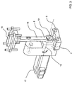
- eine perspektivische Darstellung der erfindungsgemäßen Arbeitsstation mit der zwischen der Arbeitsplattform und dem Gegenlager durchgeführten Folie,
- Fig. 2
- eine der Figur 1 entsprechende Darstellung mit deutlicher Hervorhebung der für die Bewegung der Arbeitsplattform erforderlichen Bauteile durch Weglassen der der Verstellung des Stempels dienenden Bauteile,
- Fig. 3
- eine der Figur 1 entsprechende Darstellung mit deutlicher Hervorhebung der für die Verstellung des Stempels erforderlichen Bauteile durch Weglassen der bereits in Figur 2 gezeigten Bauteile,
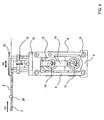
- Fig. 4
- eine Seitenansicht der erfindungsgemäßen Arbeitsstation aus Figur 1,
- Fig. 5 bis Fig. 9
- eine der Figur 4 entsprechende Darstellung einer Arbeitsstation in verschiedenen Phasen eines Arbeitstaktes.
- In der Zeichnung ist eine Arbeitsstation 1 dargestellt, die dazu dient, eine kontinuierlich bewegte, mit Produkten gefüllte Näpfe 2 aufweisende Folie 3 einzelnen Arbeitsschritten unterwerfen zu können, wobei das in der Zeichnung dargestellte Ausführungsbeispiel dem Stanzen eines Blisters aus der Folie 3 dient. Die Arbeitsstation 1 weist ein Stationsgestell 4 auf, dem ein um eine horizontale Achse 5 schwenkbarer Hebel 6 zugeordnet ist, wobei der Hebel 6 als Gabelhebel 7 mit zwei Hebelzinken 8 gestaltet und dem Hebel weiterhin ein Passivhebel 9 zugeordnet ist, die gemeinsam eine gelenkig angeschlossene Arbeitsplattform 10 tragen. Zwischen den beiden Hebelzinken 8 ist eine parallel zur Achse 5 orientierte Strebe 11 placiert, an der ein Koppelglied 12 gelagert ist, das einen Exzenter 13 trägt, der zur Verstellung des Hebels 6 mittels eines ersten Antriebes 14 genutzt wird.
- Das Stationsgestell 4 weist weiterhin einen höhenverstellbaren Stempel 15 mit einem Werkzeug 16 auf, der die Arbeitsplattform 10 durchgreift und mit dieser bewegbar ist, wobei für den Stempel 15 ein zweiter Antrieb 17 vorgesehen ist, der eine Antriebsachse 18 drehend antreibt, auf denen ein zweiter Exzenter 19 zur Verstellung des Stempels 15 sitzt.
- In Laufrichtung vor der Arbeitsstation 1, also stromauf, ist der Folie 3 eine die Lage der Näpfe 2 erfassender Sensor 20 zugeordnet, der mit einer Regeleinheit verbunden ist, durch die in Abhängigkeit der Sensorsignale die Antriebe 14,17 geregelt werden.
- Unter Bezugnahme auf die Figuren 5 bis 9 wird nachfolgend die Funktionsweise der erfindungsgemäßen Arbeitsstation 1 beschrieben. Die Folie 3 wird an dem Sensor 20 vorbei kontinuierlich durch die Arbeitsstation 1 geführt und zwar zwischen der Arbeitsplattform 10 und einem auf der Arbeitsplattform 10 angeordneten Gegenlager 21. Der erste Antrieb 14 verstellt dabei über den Exzenter 13 den Hebel 6 um die im Stationsgestell 4 angeordnete Achse 5, um so eine parallel zur Folie 3 erfolgende Verschiebung der Arbeitsplattform 10 zu erzielen, wobei über einen Bruchteil des Taktes die Verschiebung nicht nur parallel, sondern auch synchron zur Folie 3 erfolgt, um während dieser Phase des Taktes mittels des zweiten Antriebes 17 den Stempel 15 vertikal zu verstellen und den gewünschten Arbeitsschritt auszuführen, nämlich im gezeigten Ausführungsbeispiel durch Pressen des Werkzeuges 16 gegen das Gegenlager 21 einen Blister aus der Folie 3 auszustanzen. Während der Abwärtsbewegung des Stempels 15 kehrt die Arbeitsplattform 10 durch die geeignete Drehung des Exzenters 13 wieder in ihre Ausgangslage zurück. Zu beachten ist dabei, daß eine automatische Lagekorrektur der Werkzeuge 16 in Laufrichtung der Folie 3 erfolgt über die geeignete Ansteuerung des ersten Antriebes 14 und des zweiten Antriebes 17 in Abhängigkeit der von dem Sensor 20 erfaßten Daten zur Lage der Näpfe 2 in der Folie 3.
Claims (7)
- Arbeitsstation zum Bearbeiten einer vorzugsweise gefüllte Näpfe (2) aufweisenden Folie (3) durch Prägen, Perforieren, Stanzen oder vergleichbare Arbeitsschritte, dadurch gekennzeichnet, daß einem Stationsgestell (4) ein um eine horizontale Achse (5) schwenkbarer Hebel (6) zugeordnet ist, der gelenkig mit einer Arbeitsplattform (10) verbunden ist, daß das Stationsgestell (4) einen höhenverstellbaren Stempel (15) mit einem Werkzeug (16) aufweist, der die Arbeitsplattform (10) durchgreift und mit dieser bewegbar ist, und daß dem Stationsgestell (4) ein erster Antrieb (14) für den Hebel (6) und ein zweiter Antrieb (17) für den Stempel (15) zugeordnet ist.
- Arbeitsstation nach Anspruch 1, dadurch gekennzeichnet, daß durch den ersten Antrieb (14) und den zweiten Antrieb (17) jeweils Antriebsachsen (18) drehend antreibbar sind, auf denen Exzenter (13,19) zur Verstellung des Hebels (6) bzw des Stempels (15) angeordnet sind.
- Arbeitsstation nach Anspruch 2, dadurch gekennzeichnet, daß dem Hebel (6) eine parallel zur Achse (5) orientierte Strebe (11) zugeordnet ist, an der ein den Exzenter (13) tragendes Koppelglied (12) angreift.
- Arbeitsstation nach Anspruch 3, dadurch gekennzeichnet, daß der Hebel (6) als Gabelhebel (7) mit zwei Hebelzinken (8) gestaltet ist.
- Arbeitsstation nach einem der Ansprüche 1 bis 4, dadurch gekennzeichnet, daß dem Hebel (6) ein Passivhebel (9) zugeordnet ist, der um eine parallel zur Achse (5) liegende Achse drehbar ist und mit Abstand zum Hebel (6) gelenkig mit der Arbeitsplattform (10) verbunden ist.
- Arbeitsstation nach einem der Ansprüche 2 bis 5, dadurch gekennzeichnet, daß der Folie (3) ein die Lage der Näpfe (2) erfassender Sensor (20) zugeordnet ist, der mit einer Regeleinheit verbunden ist, durch die in Abhängigkeit der Sensorsignale die Antriebe (14,17) regelbar sind.
- Arbeitsstation nach einem der Ansprüche 1 bis 6, dadurch gekennzeichnet, daß die Arbeitsplattform (10) ein Gegenlager (21) für das Werkzeug trägt.
Applications Claiming Priority (2)
| Application Number | Priority Date | Filing Date | Title |
|---|---|---|---|
| DE10347775 | 2003-10-15 | ||
| DE10347775A DE10347775B4 (de) | 2003-10-15 | 2003-10-15 | Arbeitsstation |
Publications (2)
| Publication Number | Publication Date |
|---|---|
| EP1524087A1 EP1524087A1 (de) | 2005-04-20 |
| EP1524087B1 true EP1524087B1 (de) | 2006-05-24 |
Family
ID=34353405
Family Applications (1)
| Application Number | Title | Priority Date | Filing Date |
|---|---|---|---|
| EP04015080A Expired - Lifetime EP1524087B1 (de) | 2003-10-15 | 2004-06-26 | Arbeitsstation |
Country Status (7)
| Country | Link |
|---|---|
| US (1) | US7140163B2 (de) |
| EP (1) | EP1524087B1 (de) |
| JP (1) | JP4122326B2 (de) |
| AT (1) | ATE327085T1 (de) |
| DE (2) | DE10347775B4 (de) |
| DK (1) | DK1524087T3 (de) |
| ES (1) | ES2260715T3 (de) |
Families Citing this family (15)
| Publication number | Priority date | Publication date | Assignee | Title |
|---|---|---|---|---|
| DE102005009279A1 (de) * | 2005-02-25 | 2006-09-07 | Cfs Germany Gmbh | Verpackungsmaschine mit einer verschieblich angeordneten Lochstanze |
| DE102006045477A1 (de) * | 2006-09-22 | 2008-04-03 | Emil Pester Gmbh | Arbeitsstation für eine Tiefziehmaschine |
| DE102007024710B4 (de) | 2007-05-25 | 2018-09-20 | Zahoransky Ag | Blisterverpackungsmaschine mit Ausstanzstation |
| DE102009008452B3 (de) | 2009-02-11 | 2010-10-07 | Multivac Sepp Haggenmüller Gmbh & Co. Kg | Verpackungsmaschine mit einer Arbeitsstation, die ein elektrisches Hubwerk mit Grob- und Feinhub aufweist |
| CH700772A2 (de) | 2009-04-15 | 2010-10-15 | Mps Maschinen & Pack Systeme Ag | Arbeitsstation einer Blisterverpackungsmaschine. |
| DE102012000127A1 (de) * | 2012-01-06 | 2013-07-11 | Gea Cfs Germany Gmbh | Verpackungsmaschine mit einer Schneidstation |
| CN105014744A (zh) * | 2015-07-30 | 2015-11-04 | 江苏邦德机械科技发展有限公司 | 一种数控双排打孔装置 |
| CN105479542B (zh) * | 2015-12-14 | 2017-05-24 | 江南大学 | 一种包装件冲切落料装置及方法 |
| CN105836228A (zh) * | 2016-04-19 | 2016-08-10 | 郑小蒋 | 泡罩包装机的省料水平式冲裁机构 |
| CN105836178A (zh) * | 2016-04-19 | 2016-08-10 | 郑小蒋 | 省料型辊板式铝塑铝泡罩包装机 |
| CN106809452B (zh) * | 2017-04-16 | 2022-04-15 | 浙江江南制药机械有限公司 | 一种辊板泡罩包装机水平对置冲裁及打批号一体装置 |
| CN113060372B (zh) * | 2021-03-19 | 2022-04-08 | 温州大学激光与光电智能制造研究院 | 茶叶灌装设备 |
| CN116081038B (zh) * | 2023-02-01 | 2024-12-31 | 上海君诺包装技术有限公司 | 一种高速平板机的针剂包装流水线 |
| KR102728690B1 (ko) * | 2023-03-16 | 2024-11-11 | 이노로보틱스 주식회사 | 노칭 장치 |
| DE102024106265B4 (de) | 2024-03-05 | 2026-04-30 | OPTIMA life science GmbH | Presswerkzeug und Verfahren zum Pressen |
Family Cites Families (16)
| Publication number | Priority date | Publication date | Assignee | Title |
|---|---|---|---|---|
| DE2052551A1 (de) * | 1970-10-27 | 1972-06-22 | Fa. Ganzhorn u. Stirn, 7170 Schwäbisch Hall | Abfüllmaschine mit Formvorrichtung |
| DE2165366A1 (de) * | 1970-12-31 | 1972-07-27 | Kabushiki Kaisha Komatsu Seisakusho, Tokio | Doppelt wirkende mechanische Presse mit einem Gelenkgestänge |
| US3703066A (en) * | 1971-01-05 | 1972-11-21 | Maryland Cup Corp | Apparatus for feeding heat shrinkable plastic film and capping containers therewith |
| US4329830A (en) | 1979-06-22 | 1982-05-18 | Omori Machinery Co., Ltd. | Method and apparatus for packaging powdery or particle-size material |
| SE419958B (sv) * | 1979-12-28 | 1981-09-07 | Volvo Ab | Rorelsemekanism for en retlinjig rorelse med i endarna anslutande vinkelreta rorelsedelar |
| DE3118529C2 (de) * | 1981-05-09 | 1984-01-05 | Adolf Illig Maschinenbau Gmbh & Co, 7100 Heilbronn | Vorrichtung zum Ausstanzen von tiefgezogenen Teilen aus thermoplastischer Kunststoffolie |
| US4490961A (en) * | 1982-01-07 | 1985-01-01 | Raque Glenn F | Heat seal method |
| EP0111210B1 (de) * | 1982-12-07 | 1986-10-29 | Claus K. Pfankuch | Vorrichtung zum Umhüllen von Gegenständen mit einer Folie aus Kunststoff oder dergl. |
| US4892019A (en) | 1986-08-28 | 1990-01-09 | Fuji Photo Film Co., Ltd. | Sheet punching cutter |
| US5269123A (en) * | 1989-12-29 | 1993-12-14 | Massimo Marchesini | Device for sealing a film onto a blister band, particularly a polypropylene band |
| IT1273854B (it) | 1994-12-16 | 1997-07-11 | Ima Spa | Sistema per l'alimetazione di articoli negli alveoli di un nastro alveolato |
| US5964134A (en) * | 1997-06-11 | 1999-10-12 | Arends; Albert W. | Trim apparatus and method for trimming an article from a thermoplastic sheet |
| DE19734513A1 (de) * | 1997-08-08 | 1999-02-11 | Multivac Haggenmueller Kg | Hubeinrichtung für eine Arbeitsstation einer Verpackungsmaschine |
| JP3451214B2 (ja) * | 1998-07-17 | 2003-09-29 | 株式会社山田ドビー | プレス機 |
| US6745638B1 (en) * | 2000-01-12 | 2004-06-08 | Wafios Aktiengesellschaft | Device mounted onto a slider crank for generating a displacement of a part mounted onto the slide in relation to the latter |
| CN100581801C (zh) * | 2002-05-01 | 2010-01-20 | 村田机械株式会社 | 电机驱动的连杆式压力机 |
-
2003
- 2003-10-15 DE DE10347775A patent/DE10347775B4/de not_active Expired - Fee Related
-
2004
- 2004-06-26 DK DK04015080T patent/DK1524087T3/da active
- 2004-06-26 DE DE502004000617T patent/DE502004000617D1/de not_active Expired - Lifetime
- 2004-06-26 ES ES04015080T patent/ES2260715T3/es not_active Expired - Lifetime
- 2004-06-26 EP EP04015080A patent/EP1524087B1/de not_active Expired - Lifetime
- 2004-06-26 AT AT04015080T patent/ATE327085T1/de not_active IP Right Cessation
- 2004-10-12 JP JP2004297737A patent/JP4122326B2/ja not_active Expired - Fee Related
- 2004-10-13 US US10/964,586 patent/US7140163B2/en not_active Expired - Fee Related
Also Published As
| Publication number | Publication date |
|---|---|
| US20050081485A1 (en) | 2005-04-21 |
| DK1524087T3 (da) | 2006-06-12 |
| US7140163B2 (en) | 2006-11-28 |
| DE502004000617D1 (de) | 2006-06-29 |
| JP4122326B2 (ja) | 2008-07-23 |
| ATE327085T1 (de) | 2006-06-15 |
| ES2260715T3 (es) | 2006-11-01 |
| EP1524087A1 (de) | 2005-04-20 |
| JP2005118881A (ja) | 2005-05-12 |
| DE10347775B4 (de) | 2006-07-13 |
| DE10347775A1 (de) | 2005-05-19 |
Similar Documents
| Publication | Publication Date | Title |
|---|---|---|
| EP1524087B1 (de) | Arbeitsstation | |
| DE3103973C2 (de) | ||
| DE69501185T2 (de) | Ausbrechvorrichtung in einer Schneidevorrichtung | |
| DE1777355B2 (de) | Transporteinrichtung zum Transportieren von Werkstücken zwischen zwei Pressen | |
| DE2151466A1 (de) | Vorrichtung zum Bearbeiten von Bogen | |
| DE2804759A1 (de) | Vorschubeinrichtung fuer flaechenmaterial, insbesondere fuer bleche | |
| EP1330324A1 (de) | Kompakte kreismesserschere | |
| DE4127779C2 (de) | Vorrichtung zum Vorschub eines Abschnitts einer dünnen Materialbahn mit vorbestimmter Schrittlänge | |
| CH658205A5 (de) | Maschine zum kontinuierlichen abscheren und kaltstauchen des abgescherten teils, insbesondere ausgehend von drahtmaterial. | |
| DE2701443C2 (de) | Verpackungsmaschine | |
| DE69301596T2 (de) | Gerät zum Trennen von gestanzten Bögen | |
| CH653928A5 (de) | Verfahren zum biegen von profilblechen und vorrichtung zur durchfuehrung des verfahrens. | |
| EP0811438B1 (de) | Trenn- und Ausklinkvorrichtung für perforierte Bleche | |
| DE2724886C3 (de) | Verfahren und Vorrichtung zum Herstellen von schalenartigen Werkstücken | |
| DE3125843A1 (de) | "verfahren und vorrichtung zum ausstanzen von flaechigem material" | |
| DE2358281A1 (de) | Vorrichtung zur herstellung von beutelblocks aus thermoplastischer kunststoffolie | |
| DE10129429C2 (de) | Vorrichtung zur Schneidbearbeitung eines bahnförmigen Werkstücks | |
| DE2920059A1 (de) | Vorrichtung zum biegen, sicken und ablaengen der anschlussdraehte von elektrischen bauelementen | |
| EP1782930A1 (de) | Verfahren und Vorrichtung zum Beschneiden von Druckprodukten | |
| DE102006045477A1 (de) | Arbeitsstation für eine Tiefziehmaschine | |
| DE1948744C3 (de) | Zuführvorrichtung für eine Stanzpresse zum Stanzen von zwei konzentrischen Werkstücken aus Blechhalbzeug | |
| DE2632425C3 (de) | Maschine zum öffnen von Briefumschlägen | |
| DE2351069B2 (de) | Quer- und Längsschneidvorrichtung zum wahlweisen Nachschalten an eine Skinverpackungsmaschine oder an eine Thermoformmaschine | |
| DE69601265T2 (de) | Verfahren und vorrichtung zum palettieren von paketen mittels einer hubvorrichtung | |
| DE2618669B2 (de) | Vorrichtung zum taktweisen ueberfuehren von zuschnitten |
Legal Events
| Date | Code | Title | Description |
|---|---|---|---|
| PUAI | Public reference made under article 153(3) epc to a published international application that has entered the european phase |
Free format text: ORIGINAL CODE: 0009012 |
|
| 17P | Request for examination filed |
Effective date: 20041120 |
|
| AK | Designated contracting states |
Kind code of ref document: A1 Designated state(s): AT BE BG CH CY CZ DE DK EE ES FI FR GB GR HU IE IT LI LU MC NL PL PT RO SE SI SK TR |
|
| AX | Request for extension of the european patent |
Extension state: AL HR LT LV MK |
|
| GRAP | Despatch of communication of intention to grant a patent |
Free format text: ORIGINAL CODE: EPIDOSNIGR1 |
|
| AKX | Designation fees paid |
Designated state(s): AT BE BG CH CY CZ DE DK EE ES FI FR GB GR HU IE IT LI LU MC NL PL PT RO SE SI SK TR |
|
| GRAS | Grant fee paid |
Free format text: ORIGINAL CODE: EPIDOSNIGR3 |
|
| GRAA | (expected) grant |
Free format text: ORIGINAL CODE: 0009210 |
|
| AK | Designated contracting states |
Kind code of ref document: B1 Designated state(s): AT BE BG CH CY CZ DE DK EE ES FI FR GB GR HU IE IT LI LU MC NL PL PT RO SE SI SK TR |
|
| PG25 | Lapsed in a contracting state [announced via postgrant information from national office to epo] |
Ref country code: PL Free format text: LAPSE BECAUSE OF FAILURE TO SUBMIT A TRANSLATION OF THE DESCRIPTION OR TO PAY THE FEE WITHIN THE PRESCRIBED TIME-LIMIT Effective date: 20060524 Ref country code: FI Free format text: LAPSE BECAUSE OF FAILURE TO SUBMIT A TRANSLATION OF THE DESCRIPTION OR TO PAY THE FEE WITHIN THE PRESCRIBED TIME-LIMIT Effective date: 20060524 Ref country code: SK Free format text: LAPSE BECAUSE OF FAILURE TO SUBMIT A TRANSLATION OF THE DESCRIPTION OR TO PAY THE FEE WITHIN THE PRESCRIBED TIME-LIMIT Effective date: 20060524 Ref country code: SI Free format text: LAPSE BECAUSE OF FAILURE TO SUBMIT A TRANSLATION OF THE DESCRIPTION OR TO PAY THE FEE WITHIN THE PRESCRIBED TIME-LIMIT Effective date: 20060524 Ref country code: CZ Free format text: LAPSE BECAUSE OF FAILURE TO SUBMIT A TRANSLATION OF THE DESCRIPTION OR TO PAY THE FEE WITHIN THE PRESCRIBED TIME-LIMIT Effective date: 20060524 Ref country code: RO Free format text: LAPSE BECAUSE OF FAILURE TO SUBMIT A TRANSLATION OF THE DESCRIPTION OR TO PAY THE FEE WITHIN THE PRESCRIBED TIME-LIMIT Effective date: 20060524 |
|
| REG | Reference to a national code |
Ref country code: GB Ref legal event code: FG4D Free format text: NOT ENGLISH |
|
| REG | Reference to a national code |
Ref country code: CH Ref legal event code: EP Ref country code: CH Ref legal event code: NV Representative=s name: ISLER & PEDRAZZINI AG |
|
| REG | Reference to a national code |
Ref country code: DK Ref legal event code: T3 |
|
| GBT | Gb: translation of ep patent filed (gb section 77(6)(a)/1977) |
Effective date: 20060606 |
|
| REG | Reference to a national code |
Ref country code: IE Ref legal event code: FG4D Free format text: LANGUAGE OF EP DOCUMENT: GERMAN |
|
| REF | Corresponds to: |
Ref document number: 502004000617 Country of ref document: DE Date of ref document: 20060629 Kind code of ref document: P |
|
| PG25 | Lapsed in a contracting state [announced via postgrant information from national office to epo] |
Ref country code: BE Free format text: LAPSE BECAUSE OF NON-PAYMENT OF DUE FEES Effective date: 20060630 Ref country code: MC Free format text: LAPSE BECAUSE OF NON-PAYMENT OF DUE FEES Effective date: 20060630 |
|
| REG | Reference to a national code |
Ref country code: SE Ref legal event code: TRGR |
|
| PG25 | Lapsed in a contracting state [announced via postgrant information from national office to epo] |
Ref country code: PT Free format text: LAPSE BECAUSE OF FAILURE TO SUBMIT A TRANSLATION OF THE DESCRIPTION OR TO PAY THE FEE WITHIN THE PRESCRIBED TIME-LIMIT Effective date: 20061024 |
|
| REG | Reference to a national code |
Ref country code: ES Ref legal event code: FG2A Ref document number: 2260715 Country of ref document: ES Kind code of ref document: T3 |
|
| ET | Fr: translation filed | ||
| PLBE | No opposition filed within time limit |
Free format text: ORIGINAL CODE: 0009261 |
|
| STAA | Information on the status of an ep patent application or granted ep patent |
Free format text: STATUS: NO OPPOSITION FILED WITHIN TIME LIMIT |
|
| 26N | No opposition filed |
Effective date: 20070227 |
|
| PGFP | Annual fee paid to national office [announced via postgrant information from national office to epo] |
Ref country code: ES Payment date: 20070517 Year of fee payment: 4 |
|
| PGFP | Annual fee paid to national office [announced via postgrant information from national office to epo] |
Ref country code: DK Payment date: 20070604 Year of fee payment: 4 |
|
| PGFP | Annual fee paid to national office [announced via postgrant information from national office to epo] |
Ref country code: AT Payment date: 20070629 Year of fee payment: 4 Ref country code: IE Payment date: 20070629 Year of fee payment: 4 |
|
| REG | Reference to a national code |
Ref country code: CH Ref legal event code: PCAR Free format text: ISLER & PEDRAZZINI AG;POSTFACH 1772;8027 ZUERICH (CH) |
|
| PGFP | Annual fee paid to national office [announced via postgrant information from national office to epo] |
Ref country code: TR Payment date: 20070412 Year of fee payment: 4 |
|
| BERE | Be: lapsed |
Owner name: UHLMANN PAC-SYSTEME G.M.B.H. & CO. KG Effective date: 20060630 |
|
| PG25 | Lapsed in a contracting state [announced via postgrant information from national office to epo] |
Ref country code: GR Free format text: LAPSE BECAUSE OF FAILURE TO SUBMIT A TRANSLATION OF THE DESCRIPTION OR TO PAY THE FEE WITHIN THE PRESCRIBED TIME-LIMIT Effective date: 20060825 |
|
| PG25 | Lapsed in a contracting state [announced via postgrant information from national office to epo] |
Ref country code: EE Free format text: LAPSE BECAUSE OF FAILURE TO SUBMIT A TRANSLATION OF THE DESCRIPTION OR TO PAY THE FEE WITHIN THE PRESCRIBED TIME-LIMIT Effective date: 20060524 Ref country code: BG Free format text: LAPSE BECAUSE OF FAILURE TO SUBMIT A TRANSLATION OF THE DESCRIPTION OR TO PAY THE FEE WITHIN THE PRESCRIBED TIME-LIMIT Effective date: 20060824 |
|
| PG25 | Lapsed in a contracting state [announced via postgrant information from national office to epo] |
Ref country code: LU Free format text: LAPSE BECAUSE OF NON-PAYMENT OF DUE FEES Effective date: 20060626 Ref country code: HU Free format text: LAPSE BECAUSE OF FAILURE TO SUBMIT A TRANSLATION OF THE DESCRIPTION OR TO PAY THE FEE WITHIN THE PRESCRIBED TIME-LIMIT Effective date: 20061125 |
|
| PGFP | Annual fee paid to national office [announced via postgrant information from national office to epo] |
Ref country code: SE Payment date: 20080624 Year of fee payment: 5 |
|
| PG25 | Lapsed in a contracting state [announced via postgrant information from national office to epo] |
Ref country code: CY Free format text: LAPSE BECAUSE OF FAILURE TO SUBMIT A TRANSLATION OF THE DESCRIPTION OR TO PAY THE FEE WITHIN THE PRESCRIBED TIME-LIMIT Effective date: 20060524 |
|
| PGFP | Annual fee paid to national office [announced via postgrant information from national office to epo] |
Ref country code: FR Payment date: 20080423 Year of fee payment: 5 |
|
| PGFP | Annual fee paid to national office [announced via postgrant information from national office to epo] |
Ref country code: GB Payment date: 20080502 Year of fee payment: 5 |
|
| REG | Reference to a national code |
Ref country code: CH Ref legal event code: PL |
|
| REG | Reference to a national code |
Ref country code: DK Ref legal event code: EBP |
|
| NLV4 | Nl: lapsed or anulled due to non-payment of the annual fee |
Effective date: 20090101 |
|
| PG25 | Lapsed in a contracting state [announced via postgrant information from national office to epo] |
Ref country code: IE Free format text: LAPSE BECAUSE OF NON-PAYMENT OF DUE FEES Effective date: 20080626 Ref country code: AT Free format text: LAPSE BECAUSE OF NON-PAYMENT OF DUE FEES Effective date: 20080626 |
|
| PG25 | Lapsed in a contracting state [announced via postgrant information from national office to epo] |
Ref country code: NL Free format text: LAPSE BECAUSE OF NON-PAYMENT OF DUE FEES Effective date: 20090101 |
|
| PG25 | Lapsed in a contracting state [announced via postgrant information from national office to epo] |
Ref country code: LI Free format text: LAPSE BECAUSE OF NON-PAYMENT OF DUE FEES Effective date: 20080630 Ref country code: CH Free format text: LAPSE BECAUSE OF NON-PAYMENT OF DUE FEES Effective date: 20080630 |
|
| REG | Reference to a national code |
Ref country code: ES Ref legal event code: FD2A Effective date: 20080627 |
|
| PG25 | Lapsed in a contracting state [announced via postgrant information from national office to epo] |
Ref country code: ES Free format text: LAPSE BECAUSE OF NON-PAYMENT OF DUE FEES Effective date: 20080627 |
|
| PG25 | Lapsed in a contracting state [announced via postgrant information from national office to epo] |
Ref country code: DK Free format text: LAPSE BECAUSE OF NON-PAYMENT OF DUE FEES Effective date: 20090106 |
|
| GBPC | Gb: european patent ceased through non-payment of renewal fee |
Effective date: 20090626 |
|
| REG | Reference to a national code |
Ref country code: FR Ref legal event code: ST Effective date: 20100226 |
|
| PG25 | Lapsed in a contracting state [announced via postgrant information from national office to epo] |
Ref country code: FR Free format text: LAPSE BECAUSE OF NON-PAYMENT OF DUE FEES Effective date: 20090630 |
|
| PG25 | Lapsed in a contracting state [announced via postgrant information from national office to epo] |
Ref country code: DK Free format text: LAPSE BECAUSE OF NON-PAYMENT OF DUE FEES Effective date: 20080630 Ref country code: GB Free format text: LAPSE BECAUSE OF NON-PAYMENT OF DUE FEES Effective date: 20090626 |
|
| PG25 | Lapsed in a contracting state [announced via postgrant information from national office to epo] |
Ref country code: SE Free format text: LAPSE BECAUSE OF NON-PAYMENT OF DUE FEES Effective date: 20090627 |
|
| PG25 | Lapsed in a contracting state [announced via postgrant information from national office to epo] |
Ref country code: TR Free format text: LAPSE BECAUSE OF NON-PAYMENT OF DUE FEES Effective date: 20100917 |
|
| PGFP | Annual fee paid to national office [announced via postgrant information from national office to epo] |
Ref country code: IT Payment date: 20110617 Year of fee payment: 8 |
|
| PGFP | Annual fee paid to national office [announced via postgrant information from national office to epo] |
Ref country code: DE Payment date: 20110630 Year of fee payment: 8 |
|
| PG25 | Lapsed in a contracting state [announced via postgrant information from national office to epo] |
Ref country code: TR Free format text: LAPSE BECAUSE OF NON-PAYMENT OF DUE FEES Effective date: 20080626 |
|
| PG25 | Lapsed in a contracting state [announced via postgrant information from national office to epo] |
Ref country code: IT Free format text: LAPSE BECAUSE OF NON-PAYMENT OF DUE FEES Effective date: 20120626 |
|
| REG | Reference to a national code |
Ref country code: DE Ref legal event code: R119 Ref document number: 502004000617 Country of ref document: DE Effective date: 20130101 |
|
| PG25 | Lapsed in a contracting state [announced via postgrant information from national office to epo] |
Ref country code: DE Free format text: LAPSE BECAUSE OF NON-PAYMENT OF DUE FEES Effective date: 20130101 |