EP1524092A1 - Motorgetriebene Spritzgiessmaschine - Google Patents
Motorgetriebene Spritzgiessmaschine Download PDFInfo
- Publication number
- EP1524092A1 EP1524092A1 EP03396094A EP03396094A EP1524092A1 EP 1524092 A1 EP1524092 A1 EP 1524092A1 EP 03396094 A EP03396094 A EP 03396094A EP 03396094 A EP03396094 A EP 03396094A EP 1524092 A1 EP1524092 A1 EP 1524092A1
- Authority
- EP
- European Patent Office
- Prior art keywords
- plate
- mold
- movable
- injection
- fixed plate
- Prior art date
- Legal status (The legal status is an assumption and is not a legal conclusion. Google has not performed a legal analysis and makes no representation as to the accuracy of the status listed.)
- Granted
Links
- 238000001746 injection moulding Methods 0.000 title claims abstract description 48
- 238000002347 injection Methods 0.000 claims abstract description 124
- 239000007924 injection Substances 0.000 claims abstract description 124
- 239000002184 metal Substances 0.000 claims abstract description 61
- 230000007246 mechanism Effects 0.000 claims description 72
- 239000011347 resin Substances 0.000 claims description 21
- 229920005989 resin Polymers 0.000 claims description 21
- 238000013459 approach Methods 0.000 claims description 11
- 239000000463 material Substances 0.000 description 27
- 238000000465 moulding Methods 0.000 description 13
- 230000033001 locomotion Effects 0.000 description 10
- 239000012768 molten material Substances 0.000 description 3
- 239000000155 melt Substances 0.000 description 2
- 238000000034 method Methods 0.000 description 2
- 238000005096 rolling process Methods 0.000 description 2
- 230000005540 biological transmission Effects 0.000 description 1
- 230000007547 defect Effects 0.000 description 1
- 230000000694 effects Effects 0.000 description 1
- 238000010438 heat treatment Methods 0.000 description 1
- 238000009434 installation Methods 0.000 description 1
- 230000014759 maintenance of location Effects 0.000 description 1
- 238000004519 manufacturing process Methods 0.000 description 1
- 239000008188 pellet Substances 0.000 description 1
- 230000000149 penetrating effect Effects 0.000 description 1
- 230000002093 peripheral effect Effects 0.000 description 1
- 238000002360 preparation method Methods 0.000 description 1
Images





Classifications
-
- B—PERFORMING OPERATIONS; TRANSPORTING
- B29—WORKING OF PLASTICS; WORKING OF SUBSTANCES IN A PLASTIC STATE IN GENERAL
- B29C—SHAPING OR JOINING OF PLASTICS; SHAPING OF MATERIAL IN A PLASTIC STATE, NOT OTHERWISE PROVIDED FOR; AFTER-TREATMENT OF THE SHAPED PRODUCTS, e.g. REPAIRING
- B29C45/00—Injection moulding, i.e. forcing the required volume of moulding material through a nozzle into a closed mould; Apparatus therefor
- B29C45/17—Component parts, details or accessories; Auxiliary operations
- B29C45/64—Mould opening, closing or clamping devices
- B29C45/66—Mould opening, closing or clamping devices mechanical
-
- B—PERFORMING OPERATIONS; TRANSPORTING
- B29—WORKING OF PLASTICS; WORKING OF SUBSTANCES IN A PLASTIC STATE IN GENERAL
- B29C—SHAPING OR JOINING OF PLASTICS; SHAPING OF MATERIAL IN A PLASTIC STATE, NOT OTHERWISE PROVIDED FOR; AFTER-TREATMENT OF THE SHAPED PRODUCTS, e.g. REPAIRING
- B29C45/00—Injection moulding, i.e. forcing the required volume of moulding material through a nozzle into a closed mould; Apparatus therefor
- B29C45/17—Component parts, details or accessories; Auxiliary operations
- B29C2045/1784—Component parts, details or accessories not otherwise provided for; Auxiliary operations not otherwise provided for
- B29C2045/1792—Machine parts driven by an electric motor, e.g. electric servomotor
-
- B—PERFORMING OPERATIONS; TRANSPORTING
- B29—WORKING OF PLASTICS; WORKING OF SUBSTANCES IN A PLASTIC STATE IN GENERAL
- B29C—SHAPING OR JOINING OF PLASTICS; SHAPING OF MATERIAL IN A PLASTIC STATE, NOT OTHERWISE PROVIDED FOR; AFTER-TREATMENT OF THE SHAPED PRODUCTS, e.g. REPAIRING
- B29C45/00—Injection moulding, i.e. forcing the required volume of moulding material through a nozzle into a closed mould; Apparatus therefor
- B29C45/03—Injection moulding apparatus
- B29C45/04—Injection moulding apparatus using movable moulds or mould halves
- B29C45/0408—Injection moulding apparatus using movable moulds or mould halves involving at least a linear movement
- B29C45/0416—Injection moulding apparatus using movable moulds or mould halves involving at least a linear movement co-operating with fixed mould halves
-
- B—PERFORMING OPERATIONS; TRANSPORTING
- B29—WORKING OF PLASTICS; WORKING OF SUBSTANCES IN A PLASTIC STATE IN GENERAL
- B29C—SHAPING OR JOINING OF PLASTICS; SHAPING OF MATERIAL IN A PLASTIC STATE, NOT OTHERWISE PROVIDED FOR; AFTER-TREATMENT OF THE SHAPED PRODUCTS, e.g. REPAIRING
- B29C45/00—Injection moulding, i.e. forcing the required volume of moulding material through a nozzle into a closed mould; Apparatus therefor
- B29C45/16—Making multilayered or multicoloured articles
- B29C45/1615—The materials being injected at different moulding stations
- B29C45/162—The materials being injected at different moulding stations using means, e.g. mould parts, for transferring an injected part between moulding stations
-
- B—PERFORMING OPERATIONS; TRANSPORTING
- B29—WORKING OF PLASTICS; WORKING OF SUBSTANCES IN A PLASTIC STATE IN GENERAL
- B29C—SHAPING OR JOINING OF PLASTICS; SHAPING OF MATERIAL IN A PLASTIC STATE, NOT OTHERWISE PROVIDED FOR; AFTER-TREATMENT OF THE SHAPED PRODUCTS, e.g. REPAIRING
- B29C45/00—Injection moulding, i.e. forcing the required volume of moulding material through a nozzle into a closed mould; Apparatus therefor
- B29C45/17—Component parts, details or accessories; Auxiliary operations
- B29C45/46—Means for plasticising or homogenising the moulding material or forcing it into the mould
- B29C45/47—Means for plasticising or homogenising the moulding material or forcing it into the mould using screws
- B29C45/50—Axially movable screw
- B29C45/5008—Drive means therefor
-
- B—PERFORMING OPERATIONS; TRANSPORTING
- B29—WORKING OF PLASTICS; WORKING OF SUBSTANCES IN A PLASTIC STATE IN GENERAL
- B29C—SHAPING OR JOINING OF PLASTICS; SHAPING OF MATERIAL IN A PLASTIC STATE, NOT OTHERWISE PROVIDED FOR; AFTER-TREATMENT OF THE SHAPED PRODUCTS, e.g. REPAIRING
- B29C45/00—Injection moulding, i.e. forcing the required volume of moulding material through a nozzle into a closed mould; Apparatus therefor
- B29C45/17—Component parts, details or accessories; Auxiliary operations
- B29C45/46—Means for plasticising or homogenising the moulding material or forcing it into the mould
- B29C45/53—Means for plasticising or homogenising the moulding material or forcing it into the mould using injection ram or piston
- B29C45/531—Drive means therefor
-
- B—PERFORMING OPERATIONS; TRANSPORTING
- B29—WORKING OF PLASTICS; WORKING OF SUBSTANCES IN A PLASTIC STATE IN GENERAL
- B29C—SHAPING OR JOINING OF PLASTICS; SHAPING OF MATERIAL IN A PLASTIC STATE, NOT OTHERWISE PROVIDED FOR; AFTER-TREATMENT OF THE SHAPED PRODUCTS, e.g. REPAIRING
- B29C45/00—Injection moulding, i.e. forcing the required volume of moulding material through a nozzle into a closed mould; Apparatus therefor
- B29C45/17—Component parts, details or accessories; Auxiliary operations
- B29C45/46—Means for plasticising or homogenising the moulding material or forcing it into the mould
- B29C45/53—Means for plasticising or homogenising the moulding material or forcing it into the mould using injection ram or piston
- B29C45/54—Means for plasticising or homogenising the moulding material or forcing it into the mould using injection ram or piston and plasticising screw
- B29C45/541—Means for plasticising or homogenising the moulding material or forcing it into the mould using injection ram or piston and plasticising screw using a hollow plasticising screw co-operating with a coaxial injection ram
Definitions
- the present invention relates to a motor-driven injection molding apparatus in which an electric motor opens and closes metal molds, injects a molten material, and unloads a molded product.
- an injection molding machine is constituted by a metal mold opening and closing mechanism which opens and closes metal molds so as to clamp the mold, an injection mechanism which melts a pellet of a material to be molded or the like so as to inject, and a drive mechanism which automatically moves these mechanisms.
- the metal mold opening and closing mechanism is a mechanism which clamps the metal molds by a high pressure so as to carry out the mold clamping, and a mold clamping type thereof is broadly divided into a toggle type which opens and closes the metal molds and clamps the molds by a toggle mechanism, and a direct hydraulic type which directly clamps molds by a hydraulic cylinder or the like.
- the toggle type motor-driven injection molding apparatus can generate a high molding pressure by the toggle mechanism, however, since the mechanism requires a great space, most of the toggle type molding apparatuses are large-scaled.
- a direct hydraulic type injection molding apparatus 400 using a hydraulic cylinder 401 shown in Fig. 11A the apparatus itself becomes large-scaled due to a space for installing the hydraulic cylinder 401.
- the direct hydraulic type motor-driven injection molding apparatus 300 using the ball screw 301 has the following defect.
- reference numerals 305 and 402 denote a frame supporting bed plate.
- tie bars 303 are provided in a die plate 302 arranged for opening and closing the metal mold, the die plate 302 moves along the tie bars 303 by pushing by the ball screw 301 so as to allow a metal mold 304 to open and close. Further, in the structure using the ball screw 301 mentioned above, since a space S for protruding the ball screw 301 from the opening and closing mechanism or the injection mechanism is required, the apparatus is large-scaled.
- An object of the present invention is to provide a motor-driven injection molding apparatus in which an entire of the motor-driven injection molding apparatus can be made light weight and compact.
- a motor-driven injection molding machine comprising:
- the movable mold plate is guided by the slide guide supporting the lower portion of the movable mold plate, and the conventional tie bars (the guide bars) are abolished, the number of the parts is reduced, the portion for passing the tie bars therethrough is not required in the movable mold plate, and only a suitable number of, for example, two ball screw on the opposing corners pass through the movable mold plate. Accordingly, it is possible to structure the movable mold plate compact, and the structure of the plate becomes simple.
- the ball screw for example, two ball screws passing through the movable mold plate are supported in the cantilever manner, an end plate for supporting an end portion of the ball screw is not required. Accordingly, since the number of the parts can be further reduced, and the end plate is abolished, the structure becomes simple. Further, since the space for arranging the end plate is not required, the apparatus is made more compact. In this case, since the ball screws in the cantilever state are rotated via a pulley or the like for moving the movable mold plate, the movable mold plate can carry out the mold opening and closing operation with no disadvantage. Further, since the ball screws are engaged with the movable mold plate in spite of being in the cantilever state, the ball screws can be received by the movable mold plate.
- the ball screws move the movable mold plate, and the movable mold plate supports the ends of the ball screws in the cantilever state so as to be interdependent, whereby the ball screws and the movable mold plate cooperatively achieve a simplification and a compact structure of the apparatus.
- the number of the parts is reduced by abolishing the tie bars for guiding the ball screws and setting the ball screws in the cantilever state so as to abolish the end plate, so that the structure of the apparatus can be synergistically simplified and a compact structure can be achieved.
- an exclusive area for installation is reduced, and it is possible to increase the number of the motor-driven injection molding apparatuses which can be installed in a predetermined space.
- the injection amount in the injection mechanism can be controlled on the basis of a signal output from a sensor for detecting a filling state of the material to be molded into the molding cavity of the metal mold.
- the sensor is provided within the metal mold so as to detect a filling amount of the material to be molded, and a suitable injection amount can be controlled on the basis of the signal. Accordingly, it is not necessary to use two sensors comprising the sensor for detecting the moving amount of the plunger or the like and the sensor for detecting the injection pressure, as is different from the conventional one, and a cost reduction can be achieved.
- an injection tube with a plunger-in screw including a screw for mixing the material to be molded, the screw being rotatable at a fixed position in an axial direction of the injection tube, a receiving hole extending through on a center axis of the screw and storing the mixed molded material, and a plunger inserted through the receiving hole and injecting the mixed molded material.
- the screw melts the molded material to a temperature suitable for molding while instantaneously mixing the molded material, and thereafter, the plunger injects the mixed molded material to the metal mold by a suitable pressure. Accordingly, it is possible to rapidly and efficiently execute an injection process, and it is possible to make the injection mechanism compact in comparison with the normal screw type structure.
- two sets of injection mechanisms are provided so as to independently inject, two stationary metal molds are mounted to the center fixed plate in the mold opening and closing mechanism, and one movable metal mold is structured slidable in a perpendicular direction to the moving direction of the movable plate, at positions respectively fitted to two stationary metal molds by a slide mechanism, in the opening and closing side movable plate.
- a two-color molding can be carried out on the basis of the structure mentioned above. In other words, the two-color molding can be carried out even in the motor-driven injection molding apparatus in accordance with the present invention utilizing the rotation of the ball screw for the opening and closing mechanism, by mounting two stationary metal molds to the center fixed plate and achieving the structure mentioned above.
- the slide mechanism of the movable metal mold it is possible to use the same ball screw or the like as that of the movable plate.
- two sets are set as a primary side and a secondary side
- the primary side and the secondary side can be selected from the following combinations in correspondence to the molded material to be used.
- the combinations include a combination that both of the primary side and the secondary side in the two-color molding are of the plunger type, a combination that one of the primary side and the secondary side is of the plunger type and the other is of the plunger-in screw type, and a combination that both of the primary side and the secondary side are of the plunger-in screw type.
- the injection method is determined as toward the plunger type or toward the plunger-in screw type in accordance with the molded material, the shape of the target molded product, or the like. Since the plunger type has a lot of retention part at a time of injection, and has a great injection pressure loss, it is hard to inject a material having an inferior heat stability.
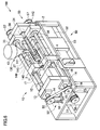
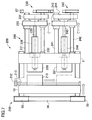
- a motor-driven injection molding apparatus 1 (hereinafter, refer also to an apparatus) corresponding to an embodiment in accordance with the present invention shown in Fig. 1 has a frame 2 forming a base of the apparatus 1, a center fixed plate 3 provided in a center of the apparatus 1 and fixed to the frame 2 by a fixing portion 4, and a mold opening and closing mechanism portion 10 and an injection mechanism portion 30 separated on the border of the center fixed plate 3. Further, drive mechanism portions 50 and 50 for driving the mold opening and closing mechanism portion 10 and the injection mechanism portion 30 are provided in an inner portion of the frame 2 and in the periphery of the frame 2.
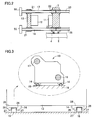
- the mold opening and closing mechanism portion 10 is provided with the center fixed plate 3, and an opening and closing side movable plate 13 (a movable mold plate) arranged so as to approach to and deviate from the center fixed plate 3. Opening and closing side ball screws 17 and 18 are inserted through the movable mold plate 13 on opposing corners. These elements are structured as shown in Fig. 2 such that a threaded portion of the opening and closing side ball screw 18 is inserted through a nut 21 for the ball screw provided in the movable mold plate 13 by screwing (since another ball screw 17 has the same structure, the ball screw 18 is exemplified).
- the opening and closing side ball screw 18 can be rotated by a opening and closing side motor 51 shown in Fig. 1 via a timing belt 56 and pulleys 55 and 55 serving as a transmission member, and the ball screw 18 is inserted through the center fixed plate 3 via a bearing 22 (Fig. 2).
- the opening and closing side ball screw 17 has the same structure. Both ball screws 17 and 18 are synchronously rotated in the same direction with each other via the timing belt 56 and the pulleys 55 and 55 by driving the motor 51, whereby the movable mold plate 13 is moved with respect to the center fixed plate 3.
- the movable mold plate (the opening and closing side movable plate) 13 in the mold opening and closing mechanism 10 is slidably guided in a direction in which the movable mold plate 13 approaches to and deviates from the center fixed plate 3, by a slide guide.
- the slide guide is provided with two linear rails 15 and 16 arranged on an upper surface of the frame 2 along a moving direction of the movable mold plate 13 and being in parallel to each other, and bearing units 14 and 14 fixed to both sides of a lower portion of the movable mold plate 13, and is structured such that the respective bearing units 14 are fitted to the linear rails 15 and 16 so as to move on the rail.
- each of the bearing units 14 is provided with balls 26 and 26 rolling along upper ball grooves corresponding to both sides of the rail 15 or 16 so as to circulate, balls 27 and 27 rolling along lower ball grooves so as to circulate, and ball holders 28 and 28 holding the balls 26 and 27, a load of the movable mold plate 13 is received by the rails 15 and 16 via each of the balls 26 and 27, and each of the balls 26 and 27 roll so as to reduce a friction in correspondence to movement of the movable mold plate 13 on the rails 15 and 16.
- end portions of the ball screws 17 and 18 protruding to an outer side (an opposite side to the center fixed plate 3) from the movable mold plate 13 are not supported by an end plate, but is set in a cantilever state, so that the end portions are screwed with the movable mold plate 13 corresponding to a subject to be driven, thereby being supported.
- the pulley 55 mentioned above is mounted to the end portion in the cantilever state of each of the ball screws 17 and 18, the timing belt 56 driven by the motor 51 is wound around the pulleys 55 and 55, and two ball screws 17 and 18 rotated in the cantilever state move the movable mold plate 13.
- Each of the ball screws 17 and 18 extends through two points on the opposing corners of the movable mold plate 13, and the structure is made such that a driving force of the ball screws 17 and 18 is applied to the movable mold plate 13 as uniformly as possible.
- the motor 51 mentioned above is an electric motor for opening and closing the mold which rotates the ball screws 17 and 18 in the cantilever state in both of forward and backward directions so as to approach the movable mold plate 13 to the center fixed plate 3 and deviate the movable mold plate 13 from the center fixed plate 3.
- the ball screws 17 and 18 exist, the ball screws are driven in the cantilever state by abolishing the end plate for supporting the end portions of the ball screws, whereby it is possible to achieve an extremely simple and compact motor-driven injection molding apparatus in which the end plate and the guide bar are abolished.
- a movable metal mold 12 is assembled in the movable mold plate 13, and a stationary metal mold 11 is assembled in the center fixed plate 3.
- the movable metal mold 12 moves together with the movable mold plate 13, a mold clamping between both the metal molds 11 and 12 is carried out with the approach of the movable mold plate 13, and a mold opening is carried out with the deviating of the movable mold plate 13.
- the injection mechanism portion 30 is provided with the center fixed plate 3, an injection side fixed plate 34, and an injection side movable plate 33 arranged between the center fixed plate 3 and the injection side fixed plate 34 and capable of moving in an axial direction. Further, through the injection side movable plate 33, there are inserted two injection side tie bars 35 and 36, and two injection side ball screws 37 and 38, on opposing corners.
- the injection side movable plate 33 is structured such as to move in an axial direction by rotation of the injection side ball screws 37 and 38 via pulleys 57 and 57 and the timing belt 56 by an injection side motor 52.
- the structure may be made such that the injection side movable plate 33 is guided with respect to the frame 2, by the slide guide shown in Figs. 1 and 3, that is, the rails 15 and 16 and the bearing units 14 and 14 assembled in the rails 15 and 16.
- the plunger 42 for injecting the molded material (the resin) is fixed onto a center axis of the injection side movable plate 33, and a cylinder 41 coaxially provided with the plunger 42 and capable of receiving the plunger 42 is arranged approximately in a center of the injection mechanism portion 30.
- the injection mechanism portion 30 of the motor-driven injection molding apparatus 1 is structured by the plunger type.
- a hopper 43 for feeding the molded material to the injection mechanism portion 30 is provided above the cylinder 41, and a heater 40 for heating the molded material so as to form a molten body to be injected is provided in an outer peripheral portion of the cylinder 41.
- the plunger 42 is structured such as to repeat a reciprocating motion in correspondence to a movement of the injection side movable plate 33 in an axial direction.
- the structure is made such that the molten material is injected to the mold opening and closing mechanism portion 10 from the injection mechanism 30 via the center fixed plate 3.
- the drive mechanism portions 50 and 50 in both end portions of the apparatus 1 mentioned above are structured such that the opening and closing side motor 51 for driving the opening and closing side ball screws 17 and 18 of the opening and closing mechanism portion 10, and the injection side motor 52 for driving the injection side ball screws 37 and 38 of the injection mechanism portion 30 are fit in the inner portion of the frame 2.
- a sensor for detecting a load current value of the drive is built in the opening and closing side motor 51.
- This sensor is provided for controlling a stroke for mold clamping in the opening and closing mechanism, and stops the driving of the motor 51 in the case that a predetermined load current value is obtained, by setting a load current value of the motor 51 in correspondence to the mold clamping pressure, thereby setting an injection preparation state.
- an ejector plate 83 within the movable metal mold 12 is provided with a sensor 70 for detecting a charging amount of a molded material W injected by the plunger 42.
- a sensor 70 for detecting a charging amount of a molded material W injected by the plunger 42.
- a leading end 73 of a molded product protruding pin 85 is energized by a web spring 72 formed on an end surface of the sensor 70 so as to slightly protrude into the cavity 74.
- the molded product protruding pin 85 slightly moves on the basis of a pressure of the molded material W, and the web spring 72 is elastically deformed approximately in a flat plate shape so as to be brought into contact with the sensor 70. Further, the structure is made such that the injection amount is controlled by the injection side motor 52 (Fig. 1) on the basis of a signal of the contacted sensor 70.
- Fig. 5 shows a simplified view in which the tie bars in the injection mechanism side are omitted and two ball screws are shown for the purpose of easy understanding.
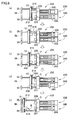
- the injection side movable plate 33 moves close to the center fixed plate 3 until the charging of the molded material into the cavity 74 (Fig. 4) is finished by the sensor 70 (Fig. 4) provided in the movable metal mold 12, thereby finishing the injection.
- the injection side motor 52 reverses the driving direction, and the plunger 42 moves close to the injection side fixed plate 34 together with the injection side movable plate 33 as shown in (c) of Fig. 5, thereby setting a standby state.
- the opening and closing side motor 51 also reverses the driving direction at a time when a fixed keeping time has passed after injection, the movable metal mold 12 moves in the opening direction together with the movable mold plate 13, thereby setting a mold opening state shown in (c) of Fig. 5.
- the molded product A is removed from the cavity on the basis of a predetermined operation of an air cylinder and the molded product is collected from a collecting portion 60.
- a modified embodiment of the motor-driven injection molding apparatus 1 is shown in Fig. 6.
- the same reference numerals are attached to the same structures and mechanisms as those of the motor-driven injection molding apparatus 1, and a description thereof will be omitted.
- a screw 145 for mixing the molded material is formed in a cylinder 141.
- a receiving hole 146 for storing the mixed molded material is formed on a center axis of the screw 145 in a penetrating manner, and a plunger 142 is slidably fitted to the receiving hole 146 in a state of allowing the screw 145 to rotate, thereby structuring a plunger-in screw type injection mechanism portion 130.
- the screw 145 is driven by the motor 53 provided in the inner portion of the frame 2.
- the molded material introduced from the hopper 43 is molten by a heater 140 while being mixed by the screw 145 within the cylinder 141, the material is uniformly and efficiently molten. Further, the molten material (resin) is stored in the receiving hole 146 formed in a leading end of the screw 145 while moving backward the plunger 142, and the molten resin in the receiving hole 146 is injected into the metal mold in accordance with a forward movement of the plunger 142.
- the plunger-in screw type structure in which the screw 145 is rotated at a fixed position and the plunger 142 moves forward in the inner portion thereof, the plunger 142 moves forward and backward via the injection side movable plate 33 mentioned above.
- Fig. 7 shows a motor-driven injection molding apparatus 200 capable of carrying out a so-called two-color molding, provided with two sets of injection mechanism portions 30 of the motor-driven injection molding apparatus 1 in Fig. 1.
- the apparatus 200 is structured such that in an opening and closing mechanism portion 290, two stationary metal molds, that is, a primary side stationary metal mold 220 and a secondary side stationary metal mold 221 are mounted to the center fixed plate 3 for the two-color molding.
- one movable metal mold 210 is mounted to the movable mold plate 13, and the movable metal mold 210 can be slid by a metal mold moving ball screw 213 arranged in a perpendicular direction to the moving direction (the axial direction) of the movable plate 13, in the direction thereof, and can be clamped to each of the two stationary metal molds 220 and 221 in accordance with this sliding motion.
- the metal mold moving ball screw 213 is rotated via a metal mold moving pulley 212 by a motor (not shown) for exclusive use of the metal mold moving ball screw, and the movable metal mold 210 moves between a first position opposing to the primary side stationary metal mold 220 and a second position opposing to the secondary side stationary metal mold 221.
- the injection mechanism portion 280 is provided with a primary side injection unit 230 for injecting the molded material (the molten resin) to the primary side stationary metal mold 220, and a secondary side injection unit 240 for injecting the molded material to the secondary side stationary metal mold 221, and both the units are driven by the same structure and mechanism.
- Both the units 230 and 240 have injection side fixed plates 234 and 244 provided in end portions, injection side ball screws 232 and 242 every two provided on respective opposing corners, tie bars 231 and 241 respectively provided on opposing corners crossing thereto, and injection side movable plates 233 and 243 respectively moving along the tie bars 231 and 241 in correspondence to the rotation of the injection side ball screws 232 and 242.
- plungers 235 and 245 are assembled in the movable plates 233 and 243, and the plungers 235 and 245 move in an axial direction within cylinders 236 and 246 storing the molten resin of the molded material. Further, the plungers 235 and 245 are selectively moved forward, whereby the molten resin is selectively injected to either the primary or secondary stationary metal molds.
- each of the opening and closing mechanism and the injection mechanism is driven by the same mechanism as that in the motor-driven injection molding apparatus 1.
- the primary side stationary metal mold 220 and the movable metal mold 210 are clamped.
- the finish of the mold clamping is detected by the load current value of the opening and closing side motor in the same manner as the motor-driven injection molding apparatus 1.
- the molten resin is injected to the primary side from the primary side injection unit 230 on the basis of the movement of the injection side movable plate 233.
- the finish of injection is defined by the sensor for detecting the charging state of the molten resin into the cavity as mentioned above.
- the injection side movable plate 233 and the movable mold plate 13 are moved in the opening direction as shown in (b)of Fig. 8.
- the injection side movable plate 243 and the movable mold plate 13 moves in the opening direction as shown in (e) of Fig. 8. Then, the two-color molded product B can be collected in accordance with an operation of an air cylinder (not shown).
- the injection mechanism portion 280 of the motor-driven injection molding apparatus 200 is structured such that in two sets of injection units, both the primary side and the secondary side are constituted by the plunger type in the motor-driven injection molding apparatus 1 in Fig. 1.
- the combination may be set to any one of a combination that one is of the plunger type and another is of the plunger-in screw type in the motor-driven injection molding apparatus 100 in Fig. 6, and a combination that both are of the plunger-in screw type.
- Fig. 9 shows a plan view of a further different embodiment.
- the mold opening and closing mechanism 10 in the motor-driven injection molding apparatus 300 is structured, in the same manner as the structure shown in Fig. 1, such that the movable mold plate 13 carries out the mold opening and closing motion with respect to the center fixed plate 3 by driving the ball screws 17 and 18 in the cantilever state, however, an injection mechanism 290 is arranged such that an injection head 82 thereof is offset by a fixed amount L with respect to a center line of the mold opening and closing mechanism 10.
- the injection mechanism 290 is provided with a first injection side fixed plate 81 and a second injection side fixed plate 134 which are provided so as to be fixed in position apart from each other at a predetermined interval, and an injection side movable plate 133 is guided therebetween along two tie bars (not shown) passing through one opposing corners in the same manner as the aspect shown in Fig. 1, and is driven by two ball screws 137 and 138 passing through another opposing corners so as to be screwed.
- Both end portions of the ball screws 137 and 138 and the tie bars (not shown) are supported by the first and second injection side fixed plates 81 and 134, and an injection operation member (an extruding member) such as a plunger or the like fixed to the injection side movable plate 133 injects the molten resin from a leading end of the injection head 82 into a cavity formed by the mold clamping state between the stationary mold 11 and the movable mold 12 via the center side fixed plate 3, in accordance with the forward movement of the injection side movable plate 133.
- an injection operation member such as a plunger or the like
- a runner corresponding to a passage of the molten resin is formed in the stationary mold 11, however, in the case that the cavity is formed in an elongated shape in a plan view (in a direction L in Fig. 9), a tendency is recognized that a resin molded product having a good quality can be obtained by a matter that the molten resin inflows from one side (one end side) in a longitudinal direction of the cavity and flows toward an opposite side (another end side) and the cavity is finally filled with the molten resin, rather than a matter that the molten resin is supplied from the center of the cavity so as to flow toward right and left sides of the cavity.
- the injection head 82 is positioned in the center of the cavity (a center line of the injection head 82 is aligned with a center line of the mold opening and closing mechanism 10), the runner to be formed in the stationary mold 11 or the like becomes long (it is necessary to elongate from the center of the cavity to one end portion).
- the injection head 82 is previously positioned close to one end side of the elongated cavity, that is, arranged in an offset manner, a forming distance of the runner can be made short, it is easy to manufacture the metal mold, and it is possible to make the structure of the runner simple.
- Fig. 10 shows a further different embodiment.
- an injection mechanism 330 employs the same structure as the structure of the mold opening and closing mechanism 10, that is, the structure in which the lower portion of the movable mold plate 13 is supported by the rails 15 and 16 of the slide guide, and the movable mold plate 13 is moved by two ball screws 17 and 18 in the cantilever state (extending through the opposing corners of the movable mold plate 13).
- an injection side movable plate 333 is arranged such that a bearing unit (Figs.
- two ball screws 337 and 338 extends from the center fixed plate 3 toward the injection mechanism 330, and the ball screws 337 and 338 pass through the plate 333 in such a manner as to be screwed with the injection side movable plate 333 at two points on the opposing corners.
- Each of the ball screws 337 and 338 is structured such that each end portion is set in a cantilever state without being supported by the end plate, and pulleys 355 and 355 are mounted to the cantilever end portions.
- a timing belt 356 wound around the pulleys 355 and 355 is driven by the injection side motor 352. Accordingly, the ball screws 337 and 338 are rotated in the same direction at the same speed, and move the injection side movable plate 333.
- a plunger 342 is forward moved by the injection side movable plate 333 for injecting the resin.
- the tie bar and the end plate are abolished in both the mold opening and closing mechanism 10 and the injection mechanism 330 side, and the movable mold plate 13 and the injection side movable plate 333 are moved by rotating the ball screws in the cantilever state, whereby the number of the parts can be reduced, and the structure of the apparatus becomes particularly simple. Further, the apparatus can be structured simple, and it is possible to obtain a great effect in simplification and compact size.
Landscapes
- Engineering & Computer Science (AREA)
- Manufacturing & Machinery (AREA)
- Mechanical Engineering (AREA)
- Moulds For Moulding Plastics Or The Like (AREA)
- Injection Moulding Of Plastics Or The Like (AREA)
Priority Applications (4)
| Application Number | Priority Date | Filing Date | Title |
|---|---|---|---|
| US10/677,319 US7156652B2 (en) | 2003-10-03 | 2003-10-03 | Motor-driven injection molding apparatus |
| DE60310565T DE60310565T2 (de) | 2003-10-03 | 2003-10-14 | Motorgetriebene Spritzgiessmaschine |
| EP03396094A EP1524092B1 (de) | 2003-10-03 | 2003-10-14 | Motorgetriebene Spritzgiessmaschine |
| DK03396094T DK1524092T3 (da) | 2003-10-03 | 2003-10-14 | Motordrevet spröjtestöbeanordning |
Applications Claiming Priority (2)
| Application Number | Priority Date | Filing Date | Title |
|---|---|---|---|
| US10/677,319 US7156652B2 (en) | 2003-10-03 | 2003-10-03 | Motor-driven injection molding apparatus |
| EP03396094A EP1524092B1 (de) | 2003-10-03 | 2003-10-14 | Motorgetriebene Spritzgiessmaschine |
Publications (2)
| Publication Number | Publication Date |
|---|---|
| EP1524092A1 true EP1524092A1 (de) | 2005-04-20 |
| EP1524092B1 EP1524092B1 (de) | 2006-12-20 |
Family
ID=34593648
Family Applications (1)
| Application Number | Title | Priority Date | Filing Date |
|---|---|---|---|
| EP03396094A Expired - Lifetime EP1524092B1 (de) | 2003-10-03 | 2003-10-14 | Motorgetriebene Spritzgiessmaschine |
Country Status (4)
| Country | Link |
|---|---|
| US (1) | US7156652B2 (de) |
| EP (1) | EP1524092B1 (de) |
| DE (1) | DE60310565T2 (de) |
| DK (1) | DK1524092T3 (de) |
Cited By (4)
| Publication number | Priority date | Publication date | Assignee | Title |
|---|---|---|---|---|
| EP1880948A3 (de) * | 2006-06-21 | 2008-07-30 | Haidlmair Holding GmbH | Transportkasten und Spritzvorrichtung für einen Transportkasten |
| US20110255811A1 (en) * | 2006-06-21 | 2011-10-20 | Nsk Ltd. | Rolling element accommodating belt for linear guide apparatus, linear guide apparatus and metallic mold for manufacturing rolling element accommodating belt |
| CN108099142A (zh) * | 2017-12-27 | 2018-06-01 | 高飞 | 一种全自动模具开合模装置 |
| EP4067041B1 (de) * | 2019-10-02 | 2024-11-06 | Siegfried Hofmann GmbH | Vorrichtung zum verarbeiten eines partikelschaummaterials zum herstellen eines partikelschaumformteils |
Families Citing this family (5)
| Publication number | Priority date | Publication date | Assignee | Title |
|---|---|---|---|---|
| US7901191B1 (en) | 2005-04-07 | 2011-03-08 | Parker Hannifan Corporation | Enclosure with fluid inducement chamber |
| CN107310103B (zh) * | 2017-06-22 | 2024-07-23 | 英格斯模具制造(中国)有限公司 | 分流板进料装置及其进料换色方法 |
| CN108877466B (zh) * | 2018-07-18 | 2021-05-25 | 河南职业技术学院 | 一种模具拆装教学用工作台 |
| IT202000023728A1 (it) * | 2020-10-08 | 2022-04-08 | Mecc Pi Erre S R L Di Pederzoli Ruggero & C | Sistema di stampaggio |
| CN117161355B (zh) * | 2023-09-06 | 2024-05-07 | 邯郸富都尔机械装备制造有限公司 | 一种可微调结构的平衡重压铸成型机 |
Citations (6)
| Publication number | Priority date | Publication date | Assignee | Title |
|---|---|---|---|---|
| JPS6168219A (ja) * | 1984-09-13 | 1986-04-08 | Fanuc Ltd | アキュムレ−タ付射出機構 |
| US5110283A (en) * | 1987-05-27 | 1992-05-05 | Mannesmann Ag | Injection molding machine having a precision clamping unit |
| JP2000094488A (ja) * | 1998-09-22 | 2000-04-04 | Daiwa Kasei Ind Co Ltd | 電動射出成形装置 |
| US20020176908A1 (en) * | 2001-05-22 | 2002-11-28 | Akira Yoshinaga | Electric direct-acting die clamping unit of an injection molding machine |
| US20030017230A1 (en) * | 2001-07-18 | 2003-01-23 | Akira Yoshinaga | Clamping unit |
| JP2003103590A (ja) * | 2002-08-06 | 2003-04-09 | Daiwa Kasei Ind Co Ltd | 電動射出成形装置 |
Family Cites Families (11)
| Publication number | Priority date | Publication date | Assignee | Title |
|---|---|---|---|---|
| DE3513388A1 (de) * | 1985-04-15 | 1986-10-16 | Bernd Dipl.-Ing. 7517 Waldbronn Schenk | Vorrichtung zur herstellung von kunststoff-formteilen insbesondere von kunststoff-hohlkoerpern |
| US6179607B1 (en) * | 1988-07-08 | 2001-01-30 | Fanuc Ltd | Two-platen mold-clamping apparatus |
| JPH084911B2 (ja) * | 1989-01-30 | 1996-01-24 | 宇部興産株式会社 | 成形機用型締装置 |
| JP3366838B2 (ja) * | 1997-08-29 | 2003-01-14 | 東芝機械株式会社 | 射出成形機の型締装置 |
| US6186770B1 (en) * | 1999-03-05 | 2001-02-13 | Amir Ziv-Av | Clamping assembly for injection molding apparatus |
| JP2001191377A (ja) * | 1999-10-25 | 2001-07-17 | Meiki Co Ltd | 型締装置 |
| DE10040819B4 (de) * | 2000-08-21 | 2012-08-09 | Kraussmaffei Technologies Gmbh | Plattenschließeinheit für eine Spritzgießmaschine |
| ITMI20010253A1 (it) * | 2001-02-08 | 2002-08-08 | Negri Bossi Spa | Gruppo di iniezione per presse ad iniezione di materiali plastici |
| US7316819B2 (en) * | 2001-03-08 | 2008-01-08 | Unigene Laboratories, Inc. | Oral peptide pharmaceutical dosage form and method of production |
| ITMI20011538A1 (it) * | 2001-07-19 | 2003-01-19 | Sandretto Ind | Metodo e pressa per la chiusura di stampi in macchine di stampaggio ad iniezione |
| AT5681U1 (de) * | 2001-10-15 | 2002-10-25 | Engel Gmbh Maschbau | Einrichtung zum plastifizieren und einspritzen von kunststoff |
-
2003
- 2003-10-03 US US10/677,319 patent/US7156652B2/en not_active Expired - Fee Related
- 2003-10-14 DE DE60310565T patent/DE60310565T2/de not_active Expired - Fee Related
- 2003-10-14 DK DK03396094T patent/DK1524092T3/da active
- 2003-10-14 EP EP03396094A patent/EP1524092B1/de not_active Expired - Lifetime
Patent Citations (6)
| Publication number | Priority date | Publication date | Assignee | Title |
|---|---|---|---|---|
| JPS6168219A (ja) * | 1984-09-13 | 1986-04-08 | Fanuc Ltd | アキュムレ−タ付射出機構 |
| US5110283A (en) * | 1987-05-27 | 1992-05-05 | Mannesmann Ag | Injection molding machine having a precision clamping unit |
| JP2000094488A (ja) * | 1998-09-22 | 2000-04-04 | Daiwa Kasei Ind Co Ltd | 電動射出成形装置 |
| US20020176908A1 (en) * | 2001-05-22 | 2002-11-28 | Akira Yoshinaga | Electric direct-acting die clamping unit of an injection molding machine |
| US20030017230A1 (en) * | 2001-07-18 | 2003-01-23 | Akira Yoshinaga | Clamping unit |
| JP2003103590A (ja) * | 2002-08-06 | 2003-04-09 | Daiwa Kasei Ind Co Ltd | 電動射出成形装置 |
Non-Patent Citations (3)
| Title |
|---|
| PATENT ABSTRACTS OF JAPAN vol. 010, no. 234 (M - 507) 14 August 1986 (1986-08-14) * |
| PATENT ABSTRACTS OF JAPAN vol. 2000, no. 07 29 September 2000 (2000-09-29) * |
| PATENT ABSTRACTS OF JAPAN vol. 2003, no. 08 6 August 2003 (2003-08-06) * |
Cited By (5)
| Publication number | Priority date | Publication date | Assignee | Title |
|---|---|---|---|---|
| EP1880948A3 (de) * | 2006-06-21 | 2008-07-30 | Haidlmair Holding GmbH | Transportkasten und Spritzvorrichtung für einen Transportkasten |
| US20110255811A1 (en) * | 2006-06-21 | 2011-10-20 | Nsk Ltd. | Rolling element accommodating belt for linear guide apparatus, linear guide apparatus and metallic mold for manufacturing rolling element accommodating belt |
| US8267586B2 (en) * | 2006-06-21 | 2012-09-18 | Nsk Ltd. | Rolling element accommodating belt for linear guide apparatus, linear guide apparatus and metallic mold for manufacturing rolling element accommodating belt |
| CN108099142A (zh) * | 2017-12-27 | 2018-06-01 | 高飞 | 一种全自动模具开合模装置 |
| EP4067041B1 (de) * | 2019-10-02 | 2024-11-06 | Siegfried Hofmann GmbH | Vorrichtung zum verarbeiten eines partikelschaummaterials zum herstellen eines partikelschaumformteils |
Also Published As
| Publication number | Publication date |
|---|---|
| US20050074517A1 (en) | 2005-04-07 |
| DE60310565D1 (de) | 2007-02-01 |
| EP1524092B1 (de) | 2006-12-20 |
| DK1524092T3 (da) | 2007-04-30 |
| DE60310565T2 (de) | 2007-09-27 |
| US7156652B2 (en) | 2007-01-02 |
Similar Documents
| Publication | Publication Date | Title |
|---|---|---|
| EP1524092B1 (de) | Motorgetriebene Spritzgiessmaschine | |
| US6093361A (en) | Clamp system and method | |
| US7261554B2 (en) | Injection unit of injection molding machine | |
| US7258543B2 (en) | Vertical micro-injection machine | |
| JP6605377B2 (ja) | 射出成形機 | |
| EP2261001B1 (de) | Vertikalmikroinjektionsmaschine | |
| US5922372A (en) | High speed locking clamp | |
| US20030219509A1 (en) | Injection molding machine | |
| JP4323900B2 (ja) | 電動射出成形装置 | |
| CA2072976C (en) | Mold clamping system | |
| EP0797498B1 (de) | Spritzgiessmaschine mit offenem rahmen | |
| JP3351512B2 (ja) | 電動射出成形装置 | |
| US6733274B2 (en) | Injection moulding machine and moulding method | |
| WO2005120801A1 (ja) | ホットランナー装置及び射出成形装置 | |
| JP3379954B1 (ja) | 電動射出成形装置 | |
| KR100553611B1 (ko) | 수직형 사출기의 회전장치 | |
| CN100443284C (zh) | 电动机驱动的注模设备 | |
| US3310841A (en) | Safety device for injection mold closing machine | |
| JPH068289A (ja) | 射出成形機 | |
| US20020142066A1 (en) | Traction type electric injection molding machine | |
| HK1077779A (en) | Motor-driven injection molding apparatus | |
| JP7270690B2 (ja) | 横型射出成形装置 | |
| KR101972475B1 (ko) | 사출 성형기 및 그 제어 방법 | |
| CN110315707A (zh) | 注射成型机的顶出杆调整方法 | |
| JPH0347165B2 (de) |
Legal Events
| Date | Code | Title | Description |
|---|---|---|---|
| PUAI | Public reference made under article 153(3) epc to a published international application that has entered the european phase |
Free format text: ORIGINAL CODE: 0009012 |
|
| AK | Designated contracting states |
Kind code of ref document: A1 Designated state(s): AT BE BG CH CY CZ DE DK EE ES FI FR GB GR HU IE IT LI LU MC NL PT RO SE SI SK TR |
|
| AX | Request for extension of the european patent |
Extension state: AL LT LV MK |
|
| 17P | Request for examination filed |
Effective date: 20051003 |
|
| AKX | Designation fees paid |
Designated state(s): DE DK FR GB IT NL |
|
| GRAP | Despatch of communication of intention to grant a patent |
Free format text: ORIGINAL CODE: EPIDOSNIGR1 |
|
| GRAS | Grant fee paid |
Free format text: ORIGINAL CODE: EPIDOSNIGR3 |
|
| GRAA | (expected) grant |
Free format text: ORIGINAL CODE: 0009210 |
|
| AK | Designated contracting states |
Kind code of ref document: B1 Designated state(s): DE DK FR GB IT NL |
|
| REG | Reference to a national code |
Ref country code: GB Ref legal event code: FG4D |
|
| REF | Corresponds to: |
Ref document number: 60310565 Country of ref document: DE Date of ref document: 20070201 Kind code of ref document: P |
|
| REG | Reference to a national code |
Ref country code: DK Ref legal event code: T3 |
|
| ET | Fr: translation filed | ||
| PLBE | No opposition filed within time limit |
Free format text: ORIGINAL CODE: 0009261 |
|
| STAA | Information on the status of an ep patent application or granted ep patent |
Free format text: STATUS: NO OPPOSITION FILED WITHIN TIME LIMIT |
|
| 26N | No opposition filed |
Effective date: 20070921 |
|
| PGFP | Annual fee paid to national office [announced via postgrant information from national office to epo] |
Ref country code: NL Payment date: 20081031 Year of fee payment: 6 |
|
| PGFP | Annual fee paid to national office [announced via postgrant information from national office to epo] |
Ref country code: DK Payment date: 20081031 Year of fee payment: 6 |
|
| PGFP | Annual fee paid to national office [announced via postgrant information from national office to epo] |
Ref country code: IT Payment date: 20081031 Year of fee payment: 6 |
|
| PGFP | Annual fee paid to national office [announced via postgrant information from national office to epo] |
Ref country code: FR Payment date: 20081031 Year of fee payment: 6 |
|
| PGFP | Annual fee paid to national office [announced via postgrant information from national office to epo] |
Ref country code: DE Payment date: 20081219 Year of fee payment: 6 |
|
| PGFP | Annual fee paid to national office [announced via postgrant information from national office to epo] |
Ref country code: GB Payment date: 20081028 Year of fee payment: 6 |
|
| REG | Reference to a national code |
Ref country code: NL Ref legal event code: V1 Effective date: 20100501 |
|
| REG | Reference to a national code |
Ref country code: DK Ref legal event code: EBP |
|
| REG | Reference to a national code |
Ref country code: FR Ref legal event code: ST Effective date: 20100630 |
|
| PG25 | Lapsed in a contracting state [announced via postgrant information from national office to epo] |
Ref country code: DE Free format text: LAPSE BECAUSE OF NON-PAYMENT OF DUE FEES Effective date: 20100501 Ref country code: NL Free format text: LAPSE BECAUSE OF NON-PAYMENT OF DUE FEES Effective date: 20100501 Ref country code: FR Free format text: LAPSE BECAUSE OF NON-PAYMENT OF DUE FEES Effective date: 20091102 |
|
| PG25 | Lapsed in a contracting state [announced via postgrant information from national office to epo] |
Ref country code: GB Free format text: LAPSE BECAUSE OF NON-PAYMENT OF DUE FEES Effective date: 20091014 |
|
| PG25 | Lapsed in a contracting state [announced via postgrant information from national office to epo] |
Ref country code: DK Free format text: LAPSE BECAUSE OF NON-PAYMENT OF DUE FEES Effective date: 20091031 |
|
| PG25 | Lapsed in a contracting state [announced via postgrant information from national office to epo] |
Ref country code: IT Free format text: LAPSE BECAUSE OF NON-PAYMENT OF DUE FEES Effective date: 20091014 |