EP1524393A2 - Scharnier mit einstellbarem Scharnierzapfen - Google Patents
Scharnier mit einstellbarem Scharnierzapfen Download PDFInfo
- Publication number
- EP1524393A2 EP1524393A2 EP04104555A EP04104555A EP1524393A2 EP 1524393 A2 EP1524393 A2 EP 1524393A2 EP 04104555 A EP04104555 A EP 04104555A EP 04104555 A EP04104555 A EP 04104555A EP 1524393 A2 EP1524393 A2 EP 1524393A2
- Authority
- EP
- European Patent Office
- Prior art keywords
- pin
- hinge
- adjustable
- fixed
- elements
- Prior art date
- Legal status (The legal status is an assumption and is not a legal conclusion. Google has not performed a legal analysis and makes no representation as to the accuracy of the status listed.)
- Withdrawn
Links
- 239000012815 thermoplastic material Substances 0.000 claims description 4
- 239000003795 chemical substances by application Substances 0.000 description 1
- 230000007547 defect Effects 0.000 description 1
- 239000000428 dust Substances 0.000 description 1
- 230000000694 effects Effects 0.000 description 1
- 230000007613 environmental effect Effects 0.000 description 1
- 230000001788 irregular Effects 0.000 description 1
- 238000004519 manufacturing process Methods 0.000 description 1
- 239000000463 material Substances 0.000 description 1
Images


Classifications
-
- E—FIXED CONSTRUCTIONS
- E05—LOCKS; KEYS; WINDOW OR DOOR FITTINGS; SAFES
- E05D—HINGES OR SUSPENSION DEVICES FOR DOORS, WINDOWS OR WINGS
- E05D7/00—Hinges or pivots of special construction
- E05D7/0009—Adjustable hinges
- E05D7/0018—Adjustable hinges at the hinge axis
- E05D7/0045—Adjustable hinges at the hinge axis in a radial direction
- E05D7/0054—Adjustable hinges at the hinge axis in a radial direction by means of eccentric parts
-
- E—FIXED CONSTRUCTIONS
- E05—LOCKS; KEYS; WINDOW OR DOOR FITTINGS; SAFES
- E05D—HINGES OR SUSPENSION DEVICES FOR DOORS, WINDOWS OR WINGS
- E05D5/00—Construction of single parts, e.g. the parts for attachment
- E05D5/10—Pins, sockets or sleeves; Removable pins
- E05D5/12—Securing pins in sockets, movably or not
-
- E—FIXED CONSTRUCTIONS
- E05—LOCKS; KEYS; WINDOW OR DOOR FITTINGS; SAFES
- E05D—HINGES OR SUSPENSION DEVICES FOR DOORS, WINDOWS OR WINGS
- E05D11/00—Additional features or accessories of hinges
- E05D11/0054—Covers, e.g. for protection
-
- E—FIXED CONSTRUCTIONS
- E05—LOCKS; KEYS; WINDOW OR DOOR FITTINGS; SAFES
- E05D—HINGES OR SUSPENSION DEVICES FOR DOORS, WINDOWS OR WINGS
- E05D5/00—Construction of single parts, e.g. the parts for attachment
- E05D5/10—Pins, sockets or sleeves; Removable pins
- E05D2005/102—Pins
- E05D2005/106—Pins with non-cylindrical portions
-
- E—FIXED CONSTRUCTIONS
- E05—LOCKS; KEYS; WINDOW OR DOOR FITTINGS; SAFES
- E05D—HINGES OR SUSPENSION DEVICES FOR DOORS, WINDOWS OR WINGS
- E05D5/00—Construction of single parts, e.g. the parts for attachment
- E05D5/02—Parts for attachment, e.g. flaps
-
- E—FIXED CONSTRUCTIONS
- E05—LOCKS; KEYS; WINDOW OR DOOR FITTINGS; SAFES
- E05Y—INDEXING SCHEME ASSOCIATED WITH SUBCLASSES E05D AND E05F, RELATING TO CONSTRUCTION ELEMENTS, ELECTRIC CONTROL, POWER SUPPLY, POWER SIGNAL OR TRANSMISSION, USER INTERFACES, MOUNTING OR COUPLING, DETAILS, ACCESSORIES, AUXILIARY OPERATIONS NOT OTHERWISE PROVIDED FOR, APPLICATION THEREOF
- E05Y2600/00—Mounting or coupling arrangements for elements provided for in this subclass
- E05Y2600/60—Mounting or coupling members; Accessories therefor
- E05Y2600/622—Dowels; Pins
-
- E—FIXED CONSTRUCTIONS
- E05—LOCKS; KEYS; WINDOW OR DOOR FITTINGS; SAFES
- E05Y—INDEXING SCHEME ASSOCIATED WITH SUBCLASSES E05D AND E05F, RELATING TO CONSTRUCTION ELEMENTS, ELECTRIC CONTROL, POWER SUPPLY, POWER SIGNAL OR TRANSMISSION, USER INTERFACES, MOUNTING OR COUPLING, DETAILS, ACCESSORIES, AUXILIARY OPERATIONS NOT OTHERWISE PROVIDED FOR, APPLICATION THEREOF
- E05Y2900/00—Application of doors, windows, wings or fittings thereof
- E05Y2900/10—Application of doors, windows, wings or fittings thereof for buildings or parts thereof
- E05Y2900/13—Type of wing
- E05Y2900/132—Doors
Definitions
- the present invention relates to a pin hinge for the mounting - with ample opportunities for adjustment - of hatches and doors on supporting doorposts provided therefor.
- the present invention relates to an adjustable-pin hinge for the mounting - with ample opportunities for adjustment - of doors and hatches onto supporting doorposts provided therefor, of the type comprising a hinge element to be fixed to the doorpost, a hinge element to be fixed to the door or hatch, and a pin to be associated with said hinge elements to allow mutual rotation thereof.
- the pin consists of two parts having spaced-apart parallel axes, a cylindrical one of which parts allows free rotation of one of said elements, while the other one comprises at least one portion that may be keyed, in a plurality of angular positions, on a seat of the other element.
- reference indexes are provided on the pin and on the load-bearing element of said seat, for the purpose of grading the adjustment.
- the pin portion which may be keyed on is a right prism and the seat of said other element is of a matching shape.
- the pin of the hinge according to the invention comprises a central collar divided into two portions, one of which determines said prism portion, which may be removed and inserted into said seat in a chosen one among causes a central widening in two areas, one of which makes up said prism portion, which may be removed and introduced into said seat in a chosen one among said angular positions - as many as the faces of said prism - said prism portion being intended to become integral with the hinge element to be fixed to the doorpost, while the other portion of said collar is a cylindrical portion associated with the prism portion which bears a reference index.
- the elements to be fixed to the doorpost and to the door may be in-line or misaligned elements which receive threaded screw or nut screw inserts, or screws and nut screws, to perform the fixing.
- both elements to be fixed to the doorpost and to the door and the pin to connect such elements are made of a thermoplastic material.
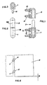
- fig. 1 is an axial section view of a hinge according to the invention with only partly-mounted in-line elements;
- fig. 2 is an external front view of the same hinge of fig. 1, fully mounted;
- fig. 3 is a cross section along the line III-III of fig. 1;
- figs. 4 and 5 are perspective views with mounted and unmounted parts, respectively, of the hinge of figs. 1-3;
- fi g. 6 shows how correction of the hinge misalignment of figs. 1-5 is carried out during mounting of a hatch
- figs. 7 and 8 are perspective views with mounted and unmounted parts, respectively, of an alternative embodiment of the hinge according to the invention, of the type having eccentric seats.
- the hinge according to the invention comprises a hinge element 1 to be fixed to a doorpost (doorpost-mounted element), a hinge element 2 to be fixed to a door or hatch (door-mounted element), and a pin 3 to be connected to said elements 1 and 2 to allow mutual rotation thereof, thereby guaranteeing door or hatch rotation.
- This pin 3 consists of two substantially cylindrical parts 4 and 5, of a similar length and which, according to a first aspect of the invention, have respective parallel, but mutually spaced apart axes.
- the first part 4 of the pin 3 allows free rotation of the hinge element 2, which hinge element 2 is mounted over said first part 4, thereby allowing free rotation of the door or hatch to which said hinge element 2 is fixed.
- the second part 5 of the pin 3 comprises instead a collar 6 with at least one non circular portion 7, which may be keyed on - in a plurality of angular positions - in a corresponding seat 8 of the hinge element 1 to be fixed to the doorpost; in this way the pin 3 becomes integral with the element 1 and hence locked in rotation.
- portion 7 is in the shape of a right regular prism (an octagon in the illustration of fig. 4) and may be inserted in the seat 8 which is of a shape matching portion 7, optionally in one of the angular locations possible, as many as the sides of said prism.
- portion 7 of the pin 3 might consist of a grooved profile or of a toothing
- the seat 8 of the hinge element 1 might be of a matching shape.
- the collar 6 of the pin 3 also comprises a cylindrical portion 7A, connected with the prism portion 7.
- This portion 7A represents a sort of washer which eases an even distribution of the load and which may further have a self-lubricating effect, provided the pin is made of suitable thermoplastic material.
- a reference index 9 is further provided on the portion 7A.
- the pin 3 Since the pin 3 consists of two parts 4 and 5 having spaced-apart parallel-axes, between said axes there is determined a vertical plane which - in the angular position of the pin 3 is defined by the coincidence of an index 10 of the element 1 with an index 9 of the collar 7A - it substantially coincides with the plane of the door frame (drawing plane of fig. 6 in the represented example). If both pins 3 of a door are in this angular position, the door rotation axis - coinciding with the axis going through the two parts 4 of the pins 3 - finds itself on the same plane as the frame, but briefly spaced apart from the axis passing through parts 5 of the pins 3.
- the door rotation axis is perfectly vertical: door rotation is regular and the same remains stable in any position it is left in. If mounting was not perfect, the door rotation axis may be slightly oblique and door rotation is irregular (when the door is left in an intermediate position, it tends to always rotate towards the open or closed position.
- FIG. 2 of the accompanying drawings clearly shows the case in which the pin 3 of the hinge according to the invention has been arranged so that the axis 4A of its cylindrical part 4 is non aligned in respect to the axis 1A of the element 1 of the hinge, in respect of the door frame plane (plane perpendicular to the drawing plane) .
- Fig. 6 represents a highly-exaggerated incorrect mounting condition which, as already mentioned above, may be very simply corrected in the following manner: remove the door, remove pin 3 from seat 8 of element 1, rotate said pin by one or more positions of its own prism portion 7, reintroduce it into seat 8; thereafter, the hinge element 2 of the door is again inserted over the pin 3. Then, a door alignment and rotation check is performed again to verify if a further adjustment is necessary (in which case the above described operations should be repeated).
- the reference R refers to the maximum obtainable correction of the hinge misalignment.
- the hinge according to the invention of figs. 1 to 6 is of the type having elements 1 and 2 in line, of a simple and closed shape, which are provided, for the fixing thereof, with threaded screw inserts 11, but nutscrew threaded inserts can equally be used.
- Figs. 7 and 8 in turn represent a hinge according to the invention having elements 1 and 2 of a more elaborate shape, with the seats for the parts 4, 5 of the pin 3 arranged eccentrically in respect to the bodies 12, these further having wing-shaped portions with seats (not shown) for the fixing screws or nutscrews; such different seats are closed on the one hand by covers 13 and on the other hand by a plug 14 for pin 3. Said covers and plugs protect the fixing area of elements 1 and 2 of the hinge and the rotation pin 3, as well as the seat therefor, against dust and environmental agents.
- this hinge of figs. 6 and 7 do not differ from those of the previous one, depicted in figs. 1 to 5, and identical are also the ways to perform the misalignment correction it allows.
- the hinge according to the invention may be manufactured in the most diverse materials. However, the manufacture thereof is particularly advantageous using thermoplastic material.
Landscapes
- Engineering & Computer Science (AREA)
- Mechanical Engineering (AREA)
- Hinges (AREA)
Applications Claiming Priority (2)
| Application Number | Priority Date | Filing Date | Title |
|---|---|---|---|
| IT002013A ITMI20032013A1 (it) | 2003-10-16 | 2003-10-16 | Cernierra a perno registrabile |
| ITMI20032013 | 2003-10-16 |
Publications (1)
| Publication Number | Publication Date |
|---|---|
| EP1524393A2 true EP1524393A2 (de) | 2005-04-20 |
Family
ID=34362424
Family Applications (1)
| Application Number | Title | Priority Date | Filing Date |
|---|---|---|---|
| EP04104555A Withdrawn EP1524393A2 (de) | 2003-10-16 | 2004-09-21 | Scharnier mit einstellbarem Scharnierzapfen |
Country Status (4)
| Country | Link |
|---|---|
| US (1) | US20050081332A1 (de) |
| EP (1) | EP1524393A2 (de) |
| CN (1) | CN1607312A (de) |
| IT (1) | ITMI20032013A1 (de) |
Cited By (1)
| Publication number | Priority date | Publication date | Assignee | Title |
|---|---|---|---|---|
| EP2339101A1 (de) * | 2010-10-20 | 2011-06-29 | ISE Automotive GmbH | Türscharnier für Kraftfahrzeuge |
Families Citing this family (4)
| Publication number | Priority date | Publication date | Assignee | Title |
|---|---|---|---|---|
| ITNA20070027U1 (it) * | 2007-07-31 | 2009-02-01 | Alessandro Barca | Cerniera regolabile per porte e/o finestre con perni di sostegno e/o fissaggio, non visibili, decentrati ed intercambiabili, applicabile per sistemi di montaggio sia a filo che a battente. |
| US10288103B2 (en) | 2015-11-30 | 2019-05-14 | Lakeshore Equipment Company | Furniture connector |
| CN114607694A (zh) * | 2022-01-12 | 2022-06-10 | 深圳市可信华成通信科技有限公司 | 一种保护夹转轴 |
| DK202470206A1 (en) * | 2024-08-06 | 2026-02-10 | Montana Furniture As | Hinge and hinge parts for furniture and related method |
Family Cites Families (16)
| Publication number | Priority date | Publication date | Assignee | Title |
|---|---|---|---|---|
| US685218A (en) * | 1901-05-29 | 1901-10-22 | Sivert B Nilsen | Hinge. |
| US787360A (en) * | 1905-01-05 | 1905-04-18 | Farbenfabriken Elberfeld Co | Process of making dialkyl-barbituric acid. |
| US1440713A (en) * | 1922-03-14 | 1923-01-02 | Merritt W Ausbourne | Self-locking hinge |
| US2588258A (en) * | 1949-04-04 | 1952-03-04 | Theodore A Lowman | Adjustable door hinge |
| USD299485S (en) * | 1986-08-25 | 1989-01-24 | Takigen Manufacturing Co., Ltd. | Hinge for refrigerator door |
| USD303491S (en) * | 1987-02-09 | 1989-09-19 | Southco, Inc. | Lift-off hinge |
| US4937916A (en) * | 1988-12-07 | 1990-07-03 | Kawneer Company, Inc. | Offset door pivot |
| USD348823S (en) * | 1991-10-11 | 1994-07-19 | Southco, Inc. | Adjustable hinge |
| USD339518S (en) * | 1991-10-11 | 1993-09-21 | Southco, Inc. | Adjustable hinge |
| IT240517Y1 (it) * | 1996-03-19 | 2001-04-02 | Maggi Spa | Cerniera per porte |
| US6178598B1 (en) * | 1996-07-15 | 2001-01-30 | Southco, Inc. | Adjustable hinge assembly |
| IT1308737B1 (it) * | 1999-06-16 | 2002-01-10 | Savio Spa | Cerniera per serramenti apribili |
| IT1308736B1 (it) * | 1999-06-16 | 2002-01-10 | Savio Spa | Cerniera per serramenti apribili |
| USD447679S1 (en) * | 2000-01-14 | 2001-09-11 | Component Hardware Group, Inc. | Adjustable hinge assembly |
| DE10013726C2 (de) * | 2000-03-21 | 2003-01-16 | Edscha Ag | Klappenscharnier |
| US6484363B1 (en) * | 2001-02-05 | 2002-11-26 | Stanley Chung | Adjustable hinge |
-
2003
- 2003-10-16 IT IT002013A patent/ITMI20032013A1/it unknown
-
2004
- 2004-09-21 EP EP04104555A patent/EP1524393A2/de not_active Withdrawn
- 2004-09-24 US US10/950,137 patent/US20050081332A1/en not_active Abandoned
- 2004-10-15 CN CNA2004100856988A patent/CN1607312A/zh active Pending
Cited By (1)
| Publication number | Priority date | Publication date | Assignee | Title |
|---|---|---|---|---|
| EP2339101A1 (de) * | 2010-10-20 | 2011-06-29 | ISE Automotive GmbH | Türscharnier für Kraftfahrzeuge |
Also Published As
| Publication number | Publication date |
|---|---|
| US20050081332A1 (en) | 2005-04-21 |
| ITMI20032013A1 (it) | 2005-04-17 |
| CN1607312A (zh) | 2005-04-20 |
Similar Documents
| Publication | Publication Date | Title |
|---|---|---|
| US5701636A (en) | Adjustable door hinge | |
| CA1291856C (en) | Hinge | |
| JP4022361B2 (ja) | 開閉ドア又は窓枠用蝶番 | |
| DE4239358C2 (de) | Gelenkband | |
| CN109196179B (zh) | 可调节铰接组件 | |
| US6434791B1 (en) | Hinges | |
| EP1524393A2 (de) | Scharnier mit einstellbarem Scharnierzapfen | |
| EP0387207B1 (de) | Verstellbares und nichtzerlegbares Scharnier für Türen, Fenster oder ähnliche Rahmen | |
| US5419640A (en) | Adjustable support for journals and hinge pins, especially for use with doors and gates | |
| IE59170B1 (en) | Adjustable door or window hinge | |
| ITBO960107A1 (it) | Cerniera per porte ed infissi metallici | |
| FI81878B (fi) | Gaongjaernsled foer foenster, doerrar eller liknande. | |
| US7805811B2 (en) | Vehicle door hinge | |
| EP0389519B1 (de) | Scharnierbänder | |
| US11939803B2 (en) | True 270-degree hinge assembly | |
| CZ20013841A3 (cs) | Závěs pro okna, dveře a podobné konstrukce | |
| KR100348046B1 (ko) | 체커 기능을 갖는 도어힌지 | |
| GB2276199A (en) | Adjustable hinge assembly | |
| DE202004004258U1 (de) | Scharnier und Duschabtrennung | |
| JP4828346B2 (ja) | 左右兼用ピボットヒンジ | |
| PL215456B1 (pl) | Czesc zawiasu do drzwi, okien i temu podobnych | |
| PL192377B1 (pl) | Zawiasa drzwiowa lub okienna | |
| GB1585128A (en) | Adjustable hinges | |
| DE10130343B4 (de) | Drehwinkelmeßvorrichtung für eine Drehwelle | |
| EP0648910A1 (de) | Scharnier für eine Tür oder Gatterwand eines Kraftfahrzeuges |
Legal Events
| Date | Code | Title | Description |
|---|---|---|---|
| PUAI | Public reference made under article 153(3) epc to a published international application that has entered the european phase |
Free format text: ORIGINAL CODE: 0009012 |
|
| AK | Designated contracting states |
Kind code of ref document: A2 Designated state(s): AT BE BG CH CY CZ DE DK EE ES FI FR GB GR HU IE IT LI LU MC NL PL PT RO SE SI SK TR |
|
| AX | Request for extension of the european patent |
Extension state: AL HR LT LV MK |
|
| STAA | Information on the status of an ep patent application or granted ep patent |
Free format text: STATUS: THE APPLICATION IS DEEMED TO BE WITHDRAWN |
|
| 18D | Application deemed to be withdrawn |
Effective date: 20080401 |