EP1524676A1 - Überspannungsableiter - Google Patents
Überspannungsableiter Download PDFInfo
- Publication number
- EP1524676A1 EP1524676A1 EP04022945A EP04022945A EP1524676A1 EP 1524676 A1 EP1524676 A1 EP 1524676A1 EP 04022945 A EP04022945 A EP 04022945A EP 04022945 A EP04022945 A EP 04022945A EP 1524676 A1 EP1524676 A1 EP 1524676A1
- Authority
- EP
- European Patent Office
- Prior art keywords
- stack
- surge voltage
- end electrodes
- voltage arrester
- cage
- Prior art date
- Legal status (The legal status is an assumption and is not a legal conclusion. Google has not performed a legal analysis and makes no representation as to the accuracy of the status listed.)
- Withdrawn
Links
Images


Classifications
-
- H—ELECTRICITY
- H01—ELECTRIC ELEMENTS
- H01C—RESISTORS
- H01C7/00—Non-adjustable resistors formed as one or more layers or coatings; Non-adjustable resistors made from powdered conducting material or powdered semi-conducting material with or without insulating material
- H01C7/10—Non-adjustable resistors formed as one or more layers or coatings; Non-adjustable resistors made from powdered conducting material or powdered semi-conducting material with or without insulating material voltage responsive, i.e. varistors
- H01C7/12—Overvoltage protection resistors; Arresters
Definitions
- the present invention relates to a surge voltage arrester.
- a surge voltage arrester is a device that is capable of protecting electrical lines and systems by constituting a barrier against surge voltages.
- surge voltage arresters particularly in medium-voltage systems
- power distribution companies the predominant part
- manufacturers of electrical devices such as distribution transformers, switches and shunting systems.
- surge voltage arrester There are various kinds of surge voltage arrester, all of which can anyway be traced back to a common structure, which is constituted by a coaxial stack of cylindrical resistive elements, such as zinc-oxide varistors, optionally spaced by metallic disks, locked between a pair of end electrodes.
- a common structure which is constituted by a coaxial stack of cylindrical resistive elements, such as zinc-oxide varistors, optionally spaced by metallic disks, locked between a pair of end electrodes.
- Such end electrodes are mutually coupled in various manners, such as for example elastic cables that connect them (thus also keeping the stack compressed) or wrappings formed by fabric tapes impregnated with unpolymerized epoxy resin or fiberglass-reinforced plastics, which wrap around the stack and the end electrodes.
- a respective threaded through pin is provided coaxially to one end electrode, or optionally to both electrodes, and pushes against one end of the stack.
- Such stack of varistors is wrapped externally by an insulating protective sheath, which is provided laterally, toward the outside, with a coaxial series of inclined surfaces; the sheath is typically made of a polymeric material, such as for example silicone rubber.
- the manufacturing method that is currently used entails assembling the stack of varistors with the end electrodes, precompressing the stack by screwing the threaded pin on the end electrode, and inserting the assembly in a mold for injection molding.
- the protective sheath is overmolded directly inside the mold onto the stack and covers it; the arrester thus formed is then extracted from the mold.
- a first drawback is linked to the fact that the precompression of the stack by screwing the threaded pin tends to displace the mutually contiguous varistors both with respect to the respective axes and with respect to the axis of the stack, thus reducing the area of contact between said varistors.
- the aim of the present invention is to provide a surge voltage arrester that solves the drawbacks noted in known types of arrester.
- an object of the present invention is to provide a surge voltage arrester that allows to have a substantially uniform surface for contact among the components of the stack of resistive elements.
- Another object of the present invention is to provide a surge voltage arrester that cannot explode due to the increase in pressure generated by electric arcs caused by internal short-circuits.
- Another object of the present invention is to provide a surge voltage arrester that can withstand important axial loads.
- Another object of the present invention is to provide a method for assembling parts of surge voltage arresters that allows to avoid the relative displacement of the resistive elements during assembly.
- Another object of the present invention is to provide a surge voltage arrester that can be manufactured with known systems and technologies.
- a surge voltage arrester comprising a stack of resistive elements arranged between end electrodes that are mutually coupled by locking means, said end electrodes being provided with means for keeping said stack compressed, said stack with at least part of said end electrodes and with said locking means being surrounded by an insulating outer sheath, said surge voltage arrester being characterized in that said locking means comprise a tubular cage for containing said stack substantially without interference, interlocking means for said end electrodes being provided at the ends of said tubular cage.
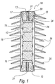
- a surge voltage arrester according to the invention is generally designated by the reference numeral 10.
- the surge voltage arrester 10 comprises a stack 11 of resistive elements 12, which are arranged between end electrodes 13, which are mutually coupled by locking means 14, described hereinafter.
- the stack 11 of resistive elements 12 comprises, at its ends, circular metallic plates 15 for contact with the end electrodes 13.
- the resistive elements 12 are constituted by cylindrical zinc oxide varistors, which in this embodiment are spaced by metallic contact disks 16.
- the circular metallic plates 15 and the metallic contact disks 16 are both preferably made of aluminum.
- the end electrodes 13 are provided with means 17, also described hereinafter, for keeping the stack 11 compressed.
- the locking means 14 comprise a tubular cage 20 for containing the stack 11 substantially without interference.
- Interlocking means 21 for the end electrodes 13 are provided at the ends of the tubular cage 20 and are constituted by a bayonet-type interlocking guide, which in this embodiment is composed of four longitudinal tracks 23 for accessing an annular undercut locking receptacle 24 for four corresponding tabs 25 provided symmetrically on the lateral surface of each one of the end electrodes 13.
- the end electrodes 13 are composed of a first part 13a, to be inserted in the cage 20, and a second part 13b, which is external to said cage.
- the tubular cage 20 forms openings 26, which are arranged in pairs so that they are mutually opposite with respect to the longitudinal axis of said cage.
- the openings 26 are provided in four longitudinal series, which are arranged symmetrically to each other with respect to the axis of the cage 20.
- the openings 26 proximate to the ends of the cage are open onto a corresponding one of the circular metallic plate 15 and onto the surface of the resistive element 12 that is adjacent thereto, while the other openings 26 are open onto portions of the surface of contiguous resistive elements 12 and accordingly onto the lateral surface of the disks 16.
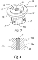
- the means 17 for keeping the stack 11 compressed comprise a threaded pin 30, which is arranged in one of the complementarily threaded through holes 31 provided coaxially in the end electrodes 13.
- the end electrode 13 on which the threaded pin 30 is not screwed has, on its second outer part 13b, two mutually opposite locators 32, which are formed by two parallel locator holes 33 for locking the electrode during the assembly of the arrester, as will become better apparent hereinafter.
- the stack 11, with the tubular cage 20 and the end electrodes 13, is surrounded by an insulating outer sheath 35, of a per se known type, which is made of polymeric material, such as for example silicone rubber, and is provided laterally, toward the outside, with a coaxial series of inclined circular surfaces 36.
- an insulating outer sheath 35 of a per se known type, which is made of polymeric material, such as for example silicone rubber, and is provided laterally, toward the outside, with a coaxial series of inclined circular surfaces 36.
- the surge voltage arrester it is first of all necessary to couple one of the end electrodes 13 to the tubular cage 20 and arrange inside said cage, according to a preset sequence, the components of the stack 11: therefore, in this embodiment, the plates 15, the resistive elements 12, and the disks 16.
- the centering and locking fixture 37 comprises two lateral cylindrical half-shells 38, which when closed together enclose the arrester 10, and two end caps 39, one of which has two centering references 40, such as for example centering pins 40a to be coupled to the parallel locator holes 33.
- the lateral cylindrical half-shells 38 have complementary jaws 29, which engage opposite to each other inside respective mutually opposite openings 26.
- the jaws 29 are constituted by pads 41, which press corresponding and mutually opposite contiguous portions of the elements of the stack 11.
- the pads 41 can slide at right angles inside corresponding cavities 42, and have elements 43 for contrasting their retraction into the cavities 42.
- the means 17 for keeping the stack 11 compressed are operated, substantially by screwing the threaded pin that pushes against the corresponding plate 15, compressing the other components of the stack.
- the invention thus described solves the problems noted in known types of surge voltage arrester; in particular, the present invention provides a surge voltage arrester that has a substantially uniform surface for contact among the components of the stack.
- the present invention provides a surge voltage arrester which, by way of the tubular cage that ensures the venting of the gases formed with the electric arcs caused by short-circuits, does not allow explosions to occur.
- the present invention provides a surge voltage arrester that can withstand important axial loads by way of the outer rigid tubular cage.
- the present invention provides a method for assembling parts of a surge voltage arrester that allows to avoid the relative displacement of the resistive elements during assembly.
- tubular cage which allows to block the components of the stack during the screwing of the threaded pin that compresses said stack.
- the materials employed may be any according to requirements and to the state of the art.
Landscapes
- Engineering & Computer Science (AREA)
- Microelectronics & Electronic Packaging (AREA)
- Physics & Mathematics (AREA)
- Electromagnetism (AREA)
- Thermistors And Varistors (AREA)
Applications Claiming Priority (2)
| Application Number | Priority Date | Filing Date | Title |
|---|---|---|---|
| ITPD20030228 | 2003-10-01 | ||
| ITPD20030228 ITPD20030228A1 (it) | 2003-10-01 | 2003-10-01 | Struttura di scaricatore di sovratensione |
Publications (1)
| Publication Number | Publication Date |
|---|---|
| EP1524676A1 true EP1524676A1 (de) | 2005-04-20 |
Family
ID=34362433
Family Applications (1)
| Application Number | Title | Priority Date | Filing Date |
|---|---|---|---|
| EP04022945A Withdrawn EP1524676A1 (de) | 2003-10-01 | 2004-09-27 | Überspannungsableiter |
Country Status (2)
| Country | Link |
|---|---|
| EP (1) | EP1524676A1 (de) |
| IT (1) | ITPD20030228A1 (de) |
Cited By (3)
| Publication number | Priority date | Publication date | Assignee | Title |
|---|---|---|---|---|
| CN105914727A (zh) * | 2016-04-22 | 2016-08-31 | 安徽大山电气有限公司 | 一种高压交流三相防爆型组合式过电压保护器 |
| DE102017203657A1 (de) | 2017-03-07 | 2018-09-13 | Siemens Aktiengesellschaft | Überspannungsableiter und Herstellungsverfahren für einen Überspannungsableiter |
| WO2025045451A1 (de) * | 2023-08-31 | 2025-03-06 | Siemens Energy Global GmbH & Co. KG | Überspannungsableiteranordnung |
Citations (3)
| Publication number | Priority date | Publication date | Assignee | Title |
|---|---|---|---|---|
| EP0393854A1 (de) * | 1989-04-18 | 1990-10-24 | Cooper Industries, Inc. | Betriebssicherer Überspannungsableiter |
| US5875090A (en) * | 1996-12-23 | 1999-02-23 | Sediver, Societe Europene D/Isolateurs En Verre Et Composite | Lightning arrestor with a thermoplastic envelope having an embossed outside surface |
| US5912611A (en) * | 1994-08-29 | 1999-06-15 | Asea Brown Boveri Ab | Surge arrester |
-
2003
- 2003-10-01 IT ITPD20030228 patent/ITPD20030228A1/it unknown
-
2004
- 2004-09-27 EP EP04022945A patent/EP1524676A1/de not_active Withdrawn
Patent Citations (3)
| Publication number | Priority date | Publication date | Assignee | Title |
|---|---|---|---|---|
| EP0393854A1 (de) * | 1989-04-18 | 1990-10-24 | Cooper Industries, Inc. | Betriebssicherer Überspannungsableiter |
| US5912611A (en) * | 1994-08-29 | 1999-06-15 | Asea Brown Boveri Ab | Surge arrester |
| US5875090A (en) * | 1996-12-23 | 1999-02-23 | Sediver, Societe Europene D/Isolateurs En Verre Et Composite | Lightning arrestor with a thermoplastic envelope having an embossed outside surface |
Cited By (4)
| Publication number | Priority date | Publication date | Assignee | Title |
|---|---|---|---|---|
| CN105914727A (zh) * | 2016-04-22 | 2016-08-31 | 安徽大山电气有限公司 | 一种高压交流三相防爆型组合式过电压保护器 |
| CN105914727B (zh) * | 2016-04-22 | 2018-04-13 | 安徽大山电气有限公司 | 一种高压交流三相防爆型组合式过电压保护器 |
| DE102017203657A1 (de) | 2017-03-07 | 2018-09-13 | Siemens Aktiengesellschaft | Überspannungsableiter und Herstellungsverfahren für einen Überspannungsableiter |
| WO2025045451A1 (de) * | 2023-08-31 | 2025-03-06 | Siemens Energy Global GmbH & Co. KG | Überspannungsableiteranordnung |
Also Published As
| Publication number | Publication date |
|---|---|
| ITPD20030228A1 (it) | 2005-04-02 |
Similar Documents
| Publication | Publication Date | Title |
|---|---|---|
| US5652690A (en) | Lightning arrester having a double enclosure assembly | |
| KR100211742B1 (ko) | 견고한 절연하우징을 가진 피뢰기 및 그 제조방법 | |
| AU2006230039B2 (en) | Over-voltage protection system | |
| CA2056274C (en) | Directionally vented underground distribution surge arrester | |
| US4456942A (en) | Gapless elbow arrester | |
| US7803003B2 (en) | Combination electrical connector | |
| US4161012A (en) | High voltage protection apparatus | |
| US4910632A (en) | Lightning arrester | |
| DE69827609D1 (de) | Verbesserungen an elektrischen überspannungsableitern | |
| US4905118A (en) | Base mounted electrical assembly | |
| JPH01272071A (ja) | モジュラ電気組立体 | |
| US6008975A (en) | Self-compressive surge arrester module and method of making same | |
| US5138517A (en) | Polymer housed electrical assemblies using modular construction | |
| US8593775B2 (en) | Surge arrester | |
| NZ331649A (en) | Self-compressive surge arrester module and method of making same | |
| CA2937282A1 (en) | Lightning arrester | |
| US5926356A (en) | End terminals for modular electrical assemblies with pressure relief | |
| EP0606409B1 (de) | Überspannungsschutz | |
| KR102384005B1 (ko) | 조립성이 우수한 피뢰기 및 이의 제조방법 | |
| CN112331537B (zh) | 一种避雷式熔断器 | |
| KR200454411Y1 (ko) | 리드선 부착형 폴리머 피뢰기 | |
| EP3414799B1 (de) | Elektrischer steckverbinder | |
| RU2125748C1 (ru) | Устройство для защиты от перенапряжений | |
| JPH0342645Y2 (de) | ||
| CN118824658A (zh) | 避雷器 |
Legal Events
| Date | Code | Title | Description |
|---|---|---|---|
| PUAI | Public reference made under article 153(3) epc to a published international application that has entered the european phase |
Free format text: ORIGINAL CODE: 0009012 |
|
| AK | Designated contracting states |
Kind code of ref document: A1 Designated state(s): AT BE BG CH CY CZ DE DK EE ES FI FR GB GR HU IE IT LI LU MC NL PL PT RO SE SI SK TR |
|
| AX | Request for extension of the european patent |
Extension state: AL HR LT LV MK |
|
| STAA | Information on the status of an ep patent application or granted ep patent |
Free format text: STATUS: THE APPLICATION HAS BEEN WITHDRAWN |
|
| 18W | Application withdrawn |
Effective date: 20050629 |