EP1526039B1 - Couverture de soute de baggage et moyens d'arrimage - Google Patents
Couverture de soute de baggage et moyens d'arrimage Download PDFInfo
- Publication number
- EP1526039B1 EP1526039B1 EP04023757A EP04023757A EP1526039B1 EP 1526039 B1 EP1526039 B1 EP 1526039B1 EP 04023757 A EP04023757 A EP 04023757A EP 04023757 A EP04023757 A EP 04023757A EP 1526039 B1 EP1526039 B1 EP 1526039B1
- Authority
- EP
- European Patent Office
- Prior art keywords
- arrangement according
- groove
- rails
- luggage compartment
- luggage
- Prior art date
- Legal status (The legal status is an assumption and is not a legal conclusion. Google has not performed a legal analysis and makes no representation as to the accuracy of the status listed.)
- Expired - Lifetime
Links
- 238000004873 anchoring Methods 0.000 claims description 25
- 239000011248 coating agent Substances 0.000 claims description 9
- 238000000576 coating method Methods 0.000 claims description 9
- 229920001971 elastomer Polymers 0.000 claims 2
- 239000000806 elastomer Substances 0.000 claims 2
- 238000004804 winding Methods 0.000 description 5
- 230000001133 acceleration Effects 0.000 description 2
- 230000007704 transition Effects 0.000 description 2
- 229910052782 aluminium Inorganic materials 0.000 description 1
- XAGFODPZIPBFFR-UHFFFAOYSA-N aluminium Chemical compound [Al] XAGFODPZIPBFFR-UHFFFAOYSA-N 0.000 description 1
- 230000006835 compression Effects 0.000 description 1
- 238000007906 compression Methods 0.000 description 1
- 238000011161 development Methods 0.000 description 1
- 230000018109 developmental process Effects 0.000 description 1
- 230000000694 effects Effects 0.000 description 1
- 229910052751 metal Inorganic materials 0.000 description 1
- 239000002184 metal Substances 0.000 description 1
- 238000012986 modification Methods 0.000 description 1
- 230000004048 modification Effects 0.000 description 1
- 238000003199 nucleic acid amplification method Methods 0.000 description 1
- 238000005192 partition Methods 0.000 description 1
Images


Classifications
-
- B—PERFORMING OPERATIONS; TRANSPORTING
- B60—VEHICLES IN GENERAL
- B60R—VEHICLES, VEHICLE FITTINGS, OR VEHICLE PARTS, NOT OTHERWISE PROVIDED FOR
- B60R5/00—Compartments within vehicle body primarily intended or sufficiently spacious for trunks, suit-cases, or the like
- B60R5/04—Compartments within vehicle body primarily intended or sufficiently spacious for trunks, suit-cases, or the like arranged at rear of vehicle
- B60R5/044—Compartments within vehicle body primarily intended or sufficiently spacious for trunks, suit-cases, or the like arranged at rear of vehicle luggage covering means, e.g. parcel shelves
- B60R5/045—Compartments within vehicle body primarily intended or sufficiently spacious for trunks, suit-cases, or the like arranged at rear of vehicle luggage covering means, e.g. parcel shelves collapsible or transformable
- B60R5/047—Compartments within vehicle body primarily intended or sufficiently spacious for trunks, suit-cases, or the like arranged at rear of vehicle luggage covering means, e.g. parcel shelves collapsible or transformable collapsible by rolling-up
-
- B—PERFORMING OPERATIONS; TRANSPORTING
- B60—VEHICLES IN GENERAL
- B60R—VEHICLES, VEHICLE FITTINGS, OR VEHICLE PARTS, NOT OTHERWISE PROVIDED FOR
- B60R7/00—Stowing or holding appliances inside vehicle primarily intended for personal property smaller than suit-cases, e.g. travelling articles, or maps
- B60R7/08—Disposition of racks, clips, holders, containers or the like for supporting specific articles
Definitions
- the loading or luggage compartments of cars were usually not lined, so there were plenty of nooks and crannies in which smaller load could be stowed.
- the designers also strive for the loading and luggage compartment. It is usually lined today with a carpet-like covering. The bottom is largely flat and pocket-like depressions are also missing in the side area. The result is that small load, which does not completely fill the loading floor, slipping as desired during start-up and braking and also when cornering on the loading floor.
- a division of the hold into a smaller compartment is not feasible in exclusively located on the ground rails.
- roller blind guide rails For clamping and guiding the roller blind guide rails are usually provided below the side windows.
- the tarpaulin is supported by a series of hoops which are also guided in lateral guide rails below the side windows.
- DE 100 47 542 A1 shows a figure which reveals two guide grooves which are formed on a loading space sidewall.
- the one guide groove should be intended to guide the end pieces of a pull-out profile of a load compartment cover.
- Another recess or groove allows the holder of partitions to segment a cargo or trunk of a car.
- a load compartment cover device is provided with a cover element, which may have the shape of a roller blind or a tarpaulin of a Roman blind.
- a cover element which may have the shape of a roller blind or a tarpaulin of a Roman blind.
- anchoring means for a cargo contained in the cargo bay are formed on at least one of the rails.
- the guide rails run over the entire depth of the cargo bay.
- the anchoring means include a bar integral with the rail which traverses the length of the rail.
- the bar together with the rail a groove that opens in the direction of the cargo bay or away from the cargo bay.
- the groove is an undercut groove.
- an anchoring means is provided, which is evident from the bottom of the hold or the cargo bay is spaced. At this anchoring means can now hang because of the distance to the floor and bags, bags and the like.
- anchoring means are present on both sides of the vehicle, it is possible to divide the cargo space below the window edge in the transverse direction. For this purpose, if necessary, further rails in the floor of the vehicle can be used, as is already known per se.
- the rails may be equipped for the cover in the manner already known with the undercut guide grooves, or as a simple, upwardly open profile, which forms only a smooth, narrow track, from which the pull-out profile for the cover is always raised upwards.
- the anchoring means may comprise a lanyard which is adjustably connected to the strip or groove. This can be a lashing eye or a lashing hook.
- the lashing member is provided with a braking device which prevents the lashing member is moved along the rail when acceleration or braking forces act on the load in the longitudinal direction of the rail.
- the braking device may be formed by an elastomeric piece or comprise an eccentric clamping device.
- FIG. 1 the broken-represented rear end 1 of a station wagon or passenger car is illustrated in perspective. It can be seen a cargo space or a cargo bay 2, bounded by a bottom 3 and two side walls, of which only the right side wall 4 can be seen. On the side wall 4 is a rear side window 5. The conclusion to the front of the cargo bay 2 forms a rear seat back 6 of a rear seat 7th
- a Abdeckrollo 8 To cover the cargo bay 2 up a Abdeckrollo 8 is provided.
- To the cover roller 8 includes a cassette 9, which extends beyond the width of the cargo bay 2 behind the rear seat back 6.
- the cassette 9 is located in receiving pockets 10 which are present in the window reveal of the rear side fastener 5.
- the cassette 9 opens at a pull-out slot 11 in the direction of the rear rear opening of the loading bay 2.
- an unrecognizable winding shaft is rotatably mounted in the usual manner, to which a roller blind 12 is attached with one edge.
- the winding shaft is biased in the sense of winding the blind sheet 2 on the winding shaft.
- a pull-out profile 13 with a handle 14 is provided at the free end of the roller blind.
- To the cover roller 8 also includes two guide rails, which are arranged below the reveal of the rear side window 5. Because of the truncated representation, only the guide rail 15 can be seen. This guide rail 15 extends, as the mirror image arranged, not visible, guide rail, on the left side of the vehicle from the cassette 9 to the rear tailgate opening of the motor vehicle. It runs approximately horizontally and is straight.
- the guide rail 15 also has anchoring means 16, by means of which cargo, for example a shopping bag 17, is to be anchored in the cargo bay 2.
- the guide rails 15 are integrated in lateral interior trim parts 18, which extend below the bottom edge of the window up to the bottom 3.
- Fig. 2 shows an enlarged perspective view of the guide rail 15. It consists of an aluminum extruded profile, which is suitably anodized, for example.
- the guide rail 15 has two mutually parallel profile sections 19 and 20, which are connected by a perpendicular thereto extending profile section 21 with each other. These profile sections 19, 20 and 21 form a groove chamber 22 of a guide groove 23, in which the extension profile 13 slides.
- the profile section 19 is provided with an upwardly projecting bar 24, wherein at the transition point between the bar 24 and the profile section 19, a rib 25 is formed, which projects opposite the profile section 19, as shown, downwards.
- the lower profile section 20 is provided at its free end with an upwardly projecting rib 26 which forms a groove slot 27 of the guide groove 23 together with the rib 25.
- an undercut groove for guiding the extension profile 13 since the width of the groove slot 27 is smaller than the width of the groove chamber 23, measured in the vertical direction.
- the rib 26 is followed by a downwardly leading bar 28, which contains anchoring openings 29 at regular intervals.
- a support strip 30 is formed which extends from the bottom of the lower profile section 20 in the vicinity of the rib 26. From this point, it first leads vertically downwards and merges at the lower free end into a leg 31 whose free end is connected to the lower edge of the strip 28.
- the strip 28 and the support strip 30 form a cavity 32 with triangular cross-section, which runs through the length of the guide rail 15.
- the guide rail 15 rests on the lower interior trim part 18, which is contoured accordingly. From the top of the guide rail 15 is another interior trim part 34 starts, which starts at the bar 24 and extends to the window 5.
- the anchoring of the guide rail 15 is not shown further, because it is understood that the guide rail is stably fixed to the sheet metal body in order to initiate the forces occurring in the body can.
- the openings 29 of the bar 16 act as anchoring members, in which further anchoring members, for example in the form of brackets 35 can be hung.
- brackets 35 which are located approximately at the height of the lower edge of the side window 5
- bags or bags 17 can be kept free-hanging with their handle.
- the anchoring means ensure that the cargo attached thereto has only limited freedom of movement within the cargo bay 2.
- the lower edge of such a network can be fixed in a arranged in the bottom 3 of the cargo bay 2 anchoring rail 36.
- the anchoring rail 36 has a ladder-like shape.
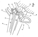
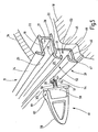
- FIGS. 3 and 4 show another embodiment of the anchoring means 16. While in the anchoring means 16 of FIGS. 1 and 2 discrete anchoring positions are given by the openings 29, in the embodiment of FIGS. 3 and 4, a continuous adjustability given.
- FIGS. 3 and 4 For explanation of FIGS. 3 and 4, the same reference numerals are used as in the embodiment of FIGS. 1 and 2, as far as it is homologous or functionally identical or similar structures or components.
- the already explained bar 28 is in the embodiment of FIGS. 3 and 4, as shown, to the vehicle side outwardly and inwardly curved, whereby at the back of the bar 28, a rearwardly open groove 37 is formed, which also again from a Nutensch 38 and a groove slot 39 composed.
- the width of the groove chamber 38 is greater than the width of the slot 39, which opens in the direction of the loading bay 2 away towards the outside of the vehicle.
- the groove 37 is not open to the loading book.
- the interior trim part 18 below the guide rail 15 has a step 40 which extends at a distance to the underside of the guide rail 15. This creates below the guide rail 15, a gap through which, a in Fig. 3 illustrated lashing 41 can be inserted.
- To the lashing 41 includes a support member 42 which has the shape of a rod. From the support member 42 go at both ends curved legs 43, which unite at the distal end of the support member 42 to two eyes, as shown in FIG. 4 reveals.
- the length of the support member 42 is slightly larger than the width of the eyelets.
- One of the two eyelets is in use slightly upwards and at the same time forms a hook, while the other eyelet over the edge of the step 40 of the interior trim part 18 is hanging down.
- the support member 42 is provided at 44 with an elastomeric coating.
- the total cross section of the support member including the elastomeric coating 44 provides the support member with an approximately oval or elliptical shape adapted to the shape of the groove chamber 38.
- the lashing 41 For attaching the lashing 41, the lashing in the position shown in Fig. 3, in which the actual eyelets are up, with the support member 42 ahead inserted through the gap between the shoulder 44 and the bottom of the guide rail 15. Then, the oval support member 42 with the uncoated part is inserted in advance through the slot 39 into the groove chamber 38.
- the short axis of the cross section of the support member 42 is smaller than the width of the slot 39.
- the lashing 41 is pivoted about an axis defined by the longitudinal axis of the support member 42 downwardly, whereby the provided with the elastomeric coating 44 portion into the groove chamber 38 inside arrives.
- the elastomeric coating 44 is sized in wall thickness such that the support member 42 jams within the groove chamber 38. The high friction exhibited by the elastomeric coating 44 within the groove chamber 38 prevents the support member 42 from sliding along the groove 37.
- the lashing 41 is thus prevented from sliding in the longitudinal direction of the guide groove 37.
- the elastomeric coating 44 provides only the initial frictional force, so that even under the influence of vibration the lashing 41 can not migrate in the longitudinal direction of the groove 37 under any circumstances.
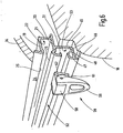
- FIGS. 5 and 6 show a further embodiment of the arrangement according to the invention. While in the previous embodiment, the locking or jamming of the lashing 41 by pivoting same within the guide groove 37, the embodiment of FIGS. 5 and 6 provides an eccentric.
- the guide rail 15, which in the region of the guide profile for the extension profile 13 in the same way is as in the embodiment of FIGS. 3 and 4 and the embodiment of FIG. 2, now has a provided below the profile section 20 arrangement which forms a groove 37 open towards the front.
- a web 45 extends downwards, the free end of which merges into a horizontally extending leg 46.
- Whose free end is provided with an L-shaped profile 47, which forms an inner edge 48.
- a bar 49 which has a similar profile, as the bar 28 of FIG. 3. Again, this results in an inwardly facing edge 51 which runs parallel and at a distance from the edge 48. Between the two edges 48 and 51, a groove slot 52 is limited, which releases the access to a groove chamber 53.
- the guide groove 37 in the embodiment of FIGS. 5 and 6 to the loading bay 2 is open. This makes it possible to bring the mecanicaldungsteil 18 to directly on the leg 46 of the guide rail 15 can.
- To the lashing 41 includes a nut 54 with two mutually parallel grooves 55 which engage over the two edges 58 and 41 in the inserted state.
- a helical compression spring 56 which concentrically surrounds a plunger 57, the sliding block 54 is resiliently biased away from a base body 58.
- De plunger sits centrally on the nut 54.
- an eye member 59 is hinged on the main body 58.
- a hinge axis 61 is provided to connect the ⁇ senglieds 59 with the main body 58.
- the hinge axis 61 passes through a hole in the main body 58 of the plunger 57th
- the eye member 59 has on the side of the main body 58 on two parallel spaced adjacent eccentric tabs 62, which can be supported on extensions 63 of the main body 58.
- the T-nut 54 is inserted through the slot 52. Then, the entire assembly is rotated about an axis defined by the plunger 57 by 90 ° until the grooves 55 are aligned with the edges 51 and 48. Now, the eye member 49 is pivoted about the horizontally extending hinge axis 61 down to the position of FIG. 5. The eccentric 62 push the hinge axis 61 of the projections 62 in the direction of the guide rail 15 away. During this movement, the plunger 57 is pulled into the housing 58, whereby the T-nut 54 with the grooves 55 on the end edges 48 and 51 jammed.
- a load compartment cover has lateral guide rails for the roller blind or roller blind. These guide rails are additionally provided with anchoring means in order to be able to determine load in the hold so far that the load only a limited movement in the hold can perform.
Landscapes
- Engineering & Computer Science (AREA)
- Mechanical Engineering (AREA)
- Operating, Guiding And Securing Of Roll- Type Closing Members (AREA)
- Fittings On The Vehicle Exterior For Carrying Loads, And Devices For Holding Or Mounting Articles (AREA)
- Vehicle Step Arrangements And Article Storage (AREA)
- Catching Or Destruction (AREA)
Claims (13)
- Dispositif (8) de recouvrement de coffre à bagages pour véhicules automobiles, destiné à masquer optiquement un espace à bagages (2) prévu dans un véhicule automobile, comprenant- un élément de recouvrement (12) qui peut être amené d'une position, dans laquelle il ferme l'espace à bagages (2), dans une position dans laquelle l'espace à bagages (2) est accessible d'en haut, au moins en partie,- deux rails (15) qui s'étendent le long de l'espace à bagages (2) et sont conçus pour maintenir l'élément de recouvrement (12) dans la position dans laquelle l'espace à bagages (2) est masqué optiquement, chaque rail (15) comportant à cet effet une rainure (23), et- au moins une rainure (37, 53) qui est prévue dans au moins l'un des rails (15), en tant que moyen d'ancrage (16) pour au moins un objet de chargement (17) contenu dans l'espace à bagages (2), la rainure (37, 53) supplémentaire étant une rainure réalisée en contre-dépouille.
- Dispositif selon la revendication 1, caractérisé par le fait que les deux rails (15) présentent des profils différents.
- Dispositif selon la revendication 1, caractérisé par le fait que les rails (15) s'étendent sur toute la longueur de l'espace à bagages (2).
- Dispositif selon la revendication 1, caractérisé par le fait que les deux rails (15) présentent des profils identiques.
- Dispositif selon la revendication 1, caractérisé par le fait qu'au moins un des rails (15) forme un profilé de guidage ouvert vers le haut pour l'élément de recouvrement (2).
- Dispositif selon la revendication 1, caractérisé par le fait que le moyen d'ancrage (16) comprend au moins un élément d'arrimage (29) délimité localement.
- Dispositif selon la revendication 1, caractérisé par le fait que la rainure (53) supplémentaire s'ouvre en direction de l'espace à bagages (2).
- Dispositif selon la revendication 1, caractérisé par le fait que la rainure (37) supplémentaire s'ouvre dans la direction opposée à l'espace à bagages (2).
- Dispositif selon la revendication 1, caractérisé par le fait que le moyen d'ancrage (16) comprend un élément d'arrimage (41) qui est relié de manière réglable à la baguette (28) ou à la rainure (37, 53).
- Dispositif selon la revendication 9, caractérisé par le fait que l'élément d'arrimage (41) est un oeillet d'arrimage ou un crochet d'arrimage.
- Dispositif selon la revendication 9, caractérisé par le fait que l'élément d'arrimage (41) est pourvu d'un moyen de freinage (44, 54).
- Dispositif selon la revendication 11, caractérisé par le fait que le moyen de freinage comprend une pièce élastomère ou un revêtement élastomère (44).
- Dispositif selon la revendication 1, caractérisé par le fait que le moyen de freinage comprend un système de serrage excentrique (54).
Priority Applications (1)
| Application Number | Priority Date | Filing Date | Title |
|---|---|---|---|
| EP06017120A EP1724154B1 (fr) | 2003-10-24 | 2004-10-06 | Couverture de soute de baggage et moyens d'arrimage |
Applications Claiming Priority (2)
| Application Number | Priority Date | Filing Date | Title |
|---|---|---|---|
| DE10349936 | 2003-10-24 | ||
| DE10349936A DE10349936A1 (de) | 2003-10-24 | 2003-10-24 | Laderaumabdeckung mit Verzurrmitteln |
Related Child Applications (1)
| Application Number | Title | Priority Date | Filing Date |
|---|---|---|---|
| EP06017120A Division EP1724154B1 (fr) | 2003-10-24 | 2004-10-06 | Couverture de soute de baggage et moyens d'arrimage |
Publications (3)
| Publication Number | Publication Date |
|---|---|
| EP1526039A2 EP1526039A2 (fr) | 2005-04-27 |
| EP1526039A3 EP1526039A3 (fr) | 2005-08-24 |
| EP1526039B1 true EP1526039B1 (fr) | 2007-02-14 |
Family
ID=34384482
Family Applications (2)
| Application Number | Title | Priority Date | Filing Date |
|---|---|---|---|
| EP06017120A Expired - Lifetime EP1724154B1 (fr) | 2003-10-24 | 2004-10-06 | Couverture de soute de baggage et moyens d'arrimage |
| EP04023757A Expired - Lifetime EP1526039B1 (fr) | 2003-10-24 | 2004-10-06 | Couverture de soute de baggage et moyens d'arrimage |
Family Applications Before (1)
| Application Number | Title | Priority Date | Filing Date |
|---|---|---|---|
| EP06017120A Expired - Lifetime EP1724154B1 (fr) | 2003-10-24 | 2004-10-06 | Couverture de soute de baggage et moyens d'arrimage |
Country Status (4)
| Country | Link |
|---|---|
| EP (2) | EP1724154B1 (fr) |
| AT (2) | ATE384638T1 (fr) |
| DE (3) | DE10349936A1 (fr) |
| ES (2) | ES2279272T3 (fr) |
Cited By (1)
| Publication number | Priority date | Publication date | Assignee | Title |
|---|---|---|---|---|
| DE102018219794A1 (de) | 2018-11-19 | 2020-05-20 | Volkswagen Aktiengesellschaft | Befestigungseinheit zur Befestigung eines Gegenstands, Befestigungssystem, Verfahren zur Herstellung einer Befestigungseinheit und Kraftfahrzeug |
Families Citing this family (12)
| Publication number | Priority date | Publication date | Assignee | Title |
|---|---|---|---|---|
| SE0501131L (sv) * | 2005-05-18 | 2006-04-18 | Gm Global Tech Operations Inc | Bagagehållarsats |
| DE102006010114A1 (de) * | 2006-02-28 | 2007-08-30 | Bos Gmbh & Co. Kg | Kraftfahrzeuginnenraum mit einem Raumausschnitt |
| DE102006049787B4 (de) * | 2006-10-21 | 2012-03-08 | Audi Ag | Vorrichtung zum Halten von Gegenständen |
| CZ302167B6 (cs) * | 2007-12-19 | 2010-11-24 | Škoda Auto a. s. | Závesný systém zavazadlového prostoru vozidla |
| CZ305656B6 (cs) * | 2008-12-18 | 2016-01-27 | Ĺ koda Auto a. s. | Závěsný systém zavazadlového prostoru vozidla |
| CZ305346B6 (cs) * | 2009-02-23 | 2015-08-12 | Ĺ koda Auto a. s. | Závěsný systém zavazadlového prostoru automobilu |
| GB2472654A (en) * | 2009-08-15 | 2011-02-16 | Bentley Motors Ltd | A retention system |
| DE102009043767A1 (de) * | 2009-09-30 | 2011-03-31 | GM Global Technology Operations, Inc., Detroit | Befestigungssystem zum Befestigen von Gegenständen an einer Rückenlehne eines Kraftfahrzeugsitzes |
| US9056950B2 (en) | 2010-07-23 | 2015-06-16 | Ticona Gmbh | Composite polymeric articles formed from extruded sheets containing a liquid crystal polymer |
| US10189413B2 (en) * | 2017-05-31 | 2019-01-29 | GM Global Technology Operations LLC | Adjustable tambour cargo deck for a vehicle |
| FR3067675B1 (fr) * | 2017-06-19 | 2019-08-02 | Treves Products, Services & Innovation | Systeme d’actionnement en position de verrouillage d’une traverse de cache-bagages de compartiment a bagages de vehicule automobile |
| DE102020113556B3 (de) | 2020-05-19 | 2021-10-28 | Humbaur Gmbh | Bordwand eines Nutzfahrzeugs, Zurrelement und Zurranordnung |
Family Cites Families (4)
| Publication number | Priority date | Publication date | Assignee | Title |
|---|---|---|---|---|
| US5685592A (en) * | 1995-12-21 | 1997-11-11 | United Technologies Automotive, Inc. | Cargo compartment cover and item support assembly |
| ATE385477T1 (de) * | 2000-07-05 | 2008-02-15 | Bos Gmbh | Laderaum für ein kraftfahrzeug |
| DE10047542A1 (de) * | 2000-07-05 | 2002-01-31 | Bos Gmbh | Laderaum für ein Kraftfahrzeug |
| DE10241925A1 (de) * | 2002-09-10 | 2004-04-01 | Adam Opel Ag | Fahrzeug mit Haltevorrichtungen für Zubehörteile |
-
2003
- 2003-10-24 DE DE10349936A patent/DE10349936A1/de not_active Withdrawn
-
2004
- 2004-10-06 ES ES04023757T patent/ES2279272T3/es not_active Expired - Lifetime
- 2004-10-06 DE DE502004002893T patent/DE502004002893D1/de not_active Expired - Lifetime
- 2004-10-06 AT AT06017120T patent/ATE384638T1/de not_active IP Right Cessation
- 2004-10-06 DE DE502004006090T patent/DE502004006090D1/de not_active Expired - Lifetime
- 2004-10-06 EP EP06017120A patent/EP1724154B1/fr not_active Expired - Lifetime
- 2004-10-06 ES ES06017120T patent/ES2299126T3/es not_active Expired - Lifetime
- 2004-10-06 AT AT04023757T patent/ATE353793T1/de not_active IP Right Cessation
- 2004-10-06 EP EP04023757A patent/EP1526039B1/fr not_active Expired - Lifetime
Cited By (2)
| Publication number | Priority date | Publication date | Assignee | Title |
|---|---|---|---|---|
| DE102018219794A1 (de) | 2018-11-19 | 2020-05-20 | Volkswagen Aktiengesellschaft | Befestigungseinheit zur Befestigung eines Gegenstands, Befestigungssystem, Verfahren zur Herstellung einer Befestigungseinheit und Kraftfahrzeug |
| DE102018219794B4 (de) | 2018-11-19 | 2024-09-05 | Volkswagen Aktiengesellschaft | Befestigungseinheit zur Befestigung eines Gegenstands, Befestigungssystem, Verfahren zur Herstellung einer Befestigungseinheit und Kraftfahrzeug |
Also Published As
| Publication number | Publication date |
|---|---|
| ES2279272T3 (es) | 2007-08-16 |
| DE502004006090D1 (de) | 2008-03-13 |
| EP1724154B1 (fr) | 2008-01-23 |
| EP1526039A3 (fr) | 2005-08-24 |
| EP1724154A1 (fr) | 2006-11-22 |
| ES2299126T3 (es) | 2008-05-16 |
| EP1526039A2 (fr) | 2005-04-27 |
| DE502004002893D1 (de) | 2007-03-29 |
| DE10349936A1 (de) | 2005-06-16 |
| ATE353793T1 (de) | 2007-03-15 |
| ATE384638T1 (de) | 2008-02-15 |
Similar Documents
| Publication | Publication Date | Title |
|---|---|---|
| DE3819766C1 (fr) | ||
| EP1526039B1 (fr) | Couverture de soute de baggage et moyens d'arrimage | |
| DE69926936T2 (de) | Gleitschiene für Fahrzeugsitz und mit solcher Schiene ausgerüsteter Sitz | |
| EP1524152B1 (fr) | Volet pour coffre | |
| DE19526666C2 (de) | Abdeckeinrichtung mit hoher Crashsicherheit | |
| DE19749158A1 (de) | Ladeboden für den Laderaum eines Fahrzeuges | |
| EP1829746A2 (fr) | Dispositif de retenue de charge | |
| EP1701863B1 (fr) | Rail de charge | |
| EP1816032A1 (fr) | Compartiment de charge d'un véhicule avec un volet cache-bagages | |
| EP1053125B1 (fr) | Plage arriere comportant des pieces d'angle mobiles | |
| AT518211B1 (de) | Runge für einen nutzfahrzeug- oder anhängeraufbau | |
| DE102007019858B4 (de) | Dachfensterrollo mit vorgespannten Gleitern | |
| DE10261393B4 (de) | Höhenverstellbares Laderaumbodensystem | |
| DE10321890B4 (de) | Befestigungsvorrichtung für einen Fahrzeugraum | |
| DE19858429A1 (de) | Vorrichtung zur Sicherung von Funktionseinheiten in einem Laderaum eines Kraftfahrzeuges und Deckabschnitt hierfür | |
| DE19728547A1 (de) | Kraftfahrzeug mit einer Rolloanordnung zwischen einem Fahrgastraum und einem Laderaum | |
| EP1826064B1 (fr) | Intérieur de véhicule avec un compartiment | |
| DE10260034B4 (de) | Ausziehbare Laderaumabdeckung für den Laderaum eines Fahrzeugs | |
| DE19738534C1 (de) | Abdeckrollo mit Führungseinrichtung | |
| DE102018208345A1 (de) | Ladeboden für einen Kofferraum eines Kraftfahrzeugs und Kraftfahrzeug mit einem solchen Ladeboden | |
| DE202009009814U1 (de) | Transportbox für Fahrzeuge | |
| DE29518982U1 (de) | Sicherheitsnetz für Fahrzeuge | |
| DE102005026671A1 (de) | Stauvorrichtung für einen Fahrzeugkofferraum | |
| DE112019005292T5 (de) | Fahrzeugschiebetürsystem | |
| DE3039522A1 (de) | Passiv-sicherheitsgurtsystem fuer motorfahrzeuge |
Legal Events
| Date | Code | Title | Description |
|---|---|---|---|
| PUAI | Public reference made under article 153(3) epc to a published international application that has entered the european phase |
Free format text: ORIGINAL CODE: 0009012 |
|
| AK | Designated contracting states |
Kind code of ref document: A2 Designated state(s): AT BE BG CH CY CZ DE DK EE ES FI FR GB GR HU IE IT LI LU MC NL PL PT RO SE SI SK TR |
|
| AX | Request for extension of the european patent |
Extension state: AL HR LT LV MK |
|
| PUAL | Search report despatched |
Free format text: ORIGINAL CODE: 0009013 |
|
| AK | Designated contracting states |
Kind code of ref document: A3 Designated state(s): AT BE BG CH CY CZ DE DK EE ES FI FR GB GR HU IE IT LI LU MC NL PL PT RO SE SI SK TR |
|
| AX | Request for extension of the european patent |
Extension state: AL HR LT LV MK |
|
| 17P | Request for examination filed |
Effective date: 20051019 |
|
| AKX | Designation fees paid |
Designated state(s): AT BE BG CH CY CZ DE DK EE ES FI FR GB GR HU IE IT LI LU MC NL PL PT RO SE SI SK TR |
|
| 17Q | First examination report despatched |
Effective date: 20051220 |
|
| GRAP | Despatch of communication of intention to grant a patent |
Free format text: ORIGINAL CODE: EPIDOSNIGR1 |
|
| GRAS | Grant fee paid |
Free format text: ORIGINAL CODE: EPIDOSNIGR3 |
|
| GRAA | (expected) grant |
Free format text: ORIGINAL CODE: 0009210 |
|
| AK | Designated contracting states |
Kind code of ref document: B1 Designated state(s): AT BE BG CH CY CZ DE DK EE ES FI FR GB GR HU IE IT LI LU MC NL PL PT RO SE SI SK TR |
|
| PG25 | Lapsed in a contracting state [announced via postgrant information from national office to epo] |
Ref country code: FI Free format text: LAPSE BECAUSE OF FAILURE TO SUBMIT A TRANSLATION OF THE DESCRIPTION OR TO PAY THE FEE WITHIN THE PRESCRIBED TIME-LIMIT Effective date: 20070214 Ref country code: IE Free format text: LAPSE BECAUSE OF FAILURE TO SUBMIT A TRANSLATION OF THE DESCRIPTION OR TO PAY THE FEE WITHIN THE PRESCRIBED TIME-LIMIT Effective date: 20070214 Ref country code: SI Free format text: LAPSE BECAUSE OF FAILURE TO SUBMIT A TRANSLATION OF THE DESCRIPTION OR TO PAY THE FEE WITHIN THE PRESCRIBED TIME-LIMIT Effective date: 20070214 Ref country code: NL Free format text: LAPSE BECAUSE OF FAILURE TO SUBMIT A TRANSLATION OF THE DESCRIPTION OR TO PAY THE FEE WITHIN THE PRESCRIBED TIME-LIMIT Effective date: 20070214 Ref country code: PL Free format text: LAPSE BECAUSE OF FAILURE TO SUBMIT A TRANSLATION OF THE DESCRIPTION OR TO PAY THE FEE WITHIN THE PRESCRIBED TIME-LIMIT Effective date: 20070214 Ref country code: DK Free format text: LAPSE BECAUSE OF FAILURE TO SUBMIT A TRANSLATION OF THE DESCRIPTION OR TO PAY THE FEE WITHIN THE PRESCRIBED TIME-LIMIT Effective date: 20070214 |
|
| REG | Reference to a national code |
Ref country code: GB Ref legal event code: FG4D Free format text: NOT ENGLISH |
|
| REG | Reference to a national code |
Ref country code: CH Ref legal event code: EP |
|
| GBT | Gb: translation of ep patent filed (gb section 77(6)(a)/1977) |
Effective date: 20070307 |
|
| REF | Corresponds to: |
Ref document number: 502004002893 Country of ref document: DE Date of ref document: 20070329 Kind code of ref document: P |
|
| REG | Reference to a national code |
Ref country code: IE Ref legal event code: FG4D Free format text: LANGUAGE OF EP DOCUMENT: GERMAN |
|
| REG | Reference to a national code |
Ref country code: SE Ref legal event code: TRGR |
|
| PG25 | Lapsed in a contracting state [announced via postgrant information from national office to epo] |
Ref country code: BG Free format text: LAPSE BECAUSE OF FAILURE TO SUBMIT A TRANSLATION OF THE DESCRIPTION OR TO PAY THE FEE WITHIN THE PRESCRIBED TIME-LIMIT Effective date: 20070515 |
|
| ET | Fr: translation filed | ||
| PG25 | Lapsed in a contracting state [announced via postgrant information from national office to epo] |
Ref country code: PT Free format text: LAPSE BECAUSE OF FAILURE TO SUBMIT A TRANSLATION OF THE DESCRIPTION OR TO PAY THE FEE WITHIN THE PRESCRIBED TIME-LIMIT Effective date: 20070716 |
|
| NLV1 | Nl: lapsed or annulled due to failure to fulfill the requirements of art. 29p and 29m of the patents act | ||
| REG | Reference to a national code |
Ref country code: ES Ref legal event code: FG2A Ref document number: 2279272 Country of ref document: ES Kind code of ref document: T3 |
|
| REG | Reference to a national code |
Ref country code: IE Ref legal event code: FD4D |
|
| PG25 | Lapsed in a contracting state [announced via postgrant information from national office to epo] |
Ref country code: SK Free format text: LAPSE BECAUSE OF FAILURE TO SUBMIT A TRANSLATION OF THE DESCRIPTION OR TO PAY THE FEE WITHIN THE PRESCRIBED TIME-LIMIT Effective date: 20070214 |
|
| PLBE | No opposition filed within time limit |
Free format text: ORIGINAL CODE: 0009261 |
|
| STAA | Information on the status of an ep patent application or granted ep patent |
Free format text: STATUS: NO OPPOSITION FILED WITHIN TIME LIMIT |
|
| PG25 | Lapsed in a contracting state [announced via postgrant information from national office to epo] |
Ref country code: RO Free format text: LAPSE BECAUSE OF FAILURE TO SUBMIT A TRANSLATION OF THE DESCRIPTION OR TO PAY THE FEE WITHIN THE PRESCRIBED TIME-LIMIT Effective date: 20070214 Ref country code: CZ Free format text: LAPSE BECAUSE OF FAILURE TO SUBMIT A TRANSLATION OF THE DESCRIPTION OR TO PAY THE FEE WITHIN THE PRESCRIBED TIME-LIMIT Effective date: 20070214 |
|
| 26N | No opposition filed |
Effective date: 20071115 |
|
| BERE | Be: lapsed |
Owner name: BOS G.M.B.H. & CO. KG Effective date: 20071031 |
|
| PG25 | Lapsed in a contracting state [announced via postgrant information from national office to epo] |
Ref country code: GR Free format text: LAPSE BECAUSE OF FAILURE TO SUBMIT A TRANSLATION OF THE DESCRIPTION OR TO PAY THE FEE WITHIN THE PRESCRIBED TIME-LIMIT Effective date: 20070515 Ref country code: IT Free format text: LAPSE BECAUSE OF FAILURE TO SUBMIT A TRANSLATION OF THE DESCRIPTION OR TO PAY THE FEE WITHIN THE PRESCRIBED TIME-LIMIT Effective date: 20070214 |
|
| PG25 | Lapsed in a contracting state [announced via postgrant information from national office to epo] |
Ref country code: MC Free format text: LAPSE BECAUSE OF NON-PAYMENT OF DUE FEES Effective date: 20071031 |
|
| PG25 | Lapsed in a contracting state [announced via postgrant information from national office to epo] |
Ref country code: BE Free format text: LAPSE BECAUSE OF NON-PAYMENT OF DUE FEES Effective date: 20071031 |
|
| PG25 | Lapsed in a contracting state [announced via postgrant information from national office to epo] |
Ref country code: EE Free format text: LAPSE BECAUSE OF FAILURE TO SUBMIT A TRANSLATION OF THE DESCRIPTION OR TO PAY THE FEE WITHIN THE PRESCRIBED TIME-LIMIT Effective date: 20070214 |
|
| PG25 | Lapsed in a contracting state [announced via postgrant information from national office to epo] |
Ref country code: AT Free format text: LAPSE BECAUSE OF NON-PAYMENT OF DUE FEES Effective date: 20071006 |
|
| PGFP | Annual fee paid to national office [announced via postgrant information from national office to epo] |
Ref country code: ES Payment date: 20081027 Year of fee payment: 5 |
|
| REG | Reference to a national code |
Ref country code: CH Ref legal event code: PL |
|
| PGFP | Annual fee paid to national office [announced via postgrant information from national office to epo] |
Ref country code: GB Payment date: 20081021 Year of fee payment: 5 |
|
| PG25 | Lapsed in a contracting state [announced via postgrant information from national office to epo] |
Ref country code: CY Free format text: LAPSE BECAUSE OF FAILURE TO SUBMIT A TRANSLATION OF THE DESCRIPTION OR TO PAY THE FEE WITHIN THE PRESCRIBED TIME-LIMIT Effective date: 20070214 |
|
| PG25 | Lapsed in a contracting state [announced via postgrant information from national office to epo] |
Ref country code: LU Free format text: LAPSE BECAUSE OF NON-PAYMENT OF DUE FEES Effective date: 20071006 |
|
| PG25 | Lapsed in a contracting state [announced via postgrant information from national office to epo] |
Ref country code: TR Free format text: LAPSE BECAUSE OF FAILURE TO SUBMIT A TRANSLATION OF THE DESCRIPTION OR TO PAY THE FEE WITHIN THE PRESCRIBED TIME-LIMIT Effective date: 20070214 Ref country code: HU Free format text: LAPSE BECAUSE OF FAILURE TO SUBMIT A TRANSLATION OF THE DESCRIPTION OR TO PAY THE FEE WITHIN THE PRESCRIBED TIME-LIMIT Effective date: 20070815 |
|
| PG25 | Lapsed in a contracting state [announced via postgrant information from national office to epo] |
Ref country code: LI Free format text: LAPSE BECAUSE OF NON-PAYMENT OF DUE FEES Effective date: 20081031 Ref country code: CH Free format text: LAPSE BECAUSE OF NON-PAYMENT OF DUE FEES Effective date: 20081031 |
|
| PG25 | Lapsed in a contracting state [announced via postgrant information from national office to epo] |
Ref country code: GB Free format text: LAPSE BECAUSE OF NON-PAYMENT OF DUE FEES Effective date: 20091006 |
|
| REG | Reference to a national code |
Ref country code: ES Ref legal event code: FD2A Effective date: 20110302 |
|
| PG25 | Lapsed in a contracting state [announced via postgrant information from national office to epo] |
Ref country code: ES Free format text: LAPSE BECAUSE OF NON-PAYMENT OF DUE FEES Effective date: 20110301 |
|
| PG25 | Lapsed in a contracting state [announced via postgrant information from national office to epo] |
Ref country code: ES Free format text: LAPSE BECAUSE OF NON-PAYMENT OF DUE FEES Effective date: 20091007 |
|
| PGFP | Annual fee paid to national office [announced via postgrant information from national office to epo] |
Ref country code: FR Payment date: 20111103 Year of fee payment: 8 Ref country code: SE Payment date: 20111021 Year of fee payment: 8 |
|
| REG | Reference to a national code |
Ref country code: FR Ref legal event code: ST Effective date: 20130628 |
|
| PG25 | Lapsed in a contracting state [announced via postgrant information from national office to epo] |
Ref country code: SE Free format text: LAPSE BECAUSE OF NON-PAYMENT OF DUE FEES Effective date: 20121007 |
|
| PG25 | Lapsed in a contracting state [announced via postgrant information from national office to epo] |
Ref country code: FR Free format text: LAPSE BECAUSE OF NON-PAYMENT OF DUE FEES Effective date: 20121031 |
|
| PGFP | Annual fee paid to national office [announced via postgrant information from national office to epo] |
Ref country code: DE Payment date: 20141031 Year of fee payment: 11 |
|
| REG | Reference to a national code |
Ref country code: DE Ref legal event code: R119 Ref document number: 502004002893 Country of ref document: DE |
|
| PG25 | Lapsed in a contracting state [announced via postgrant information from national office to epo] |
Ref country code: DE Free format text: LAPSE BECAUSE OF NON-PAYMENT OF DUE FEES Effective date: 20160503 |