EP1826064B1 - Intérieur de véhicule avec un compartiment - Google Patents
Intérieur de véhicule avec un compartiment Download PDFInfo
- Publication number
- EP1826064B1 EP1826064B1 EP07002278A EP07002278A EP1826064B1 EP 1826064 B1 EP1826064 B1 EP 1826064B1 EP 07002278 A EP07002278 A EP 07002278A EP 07002278 A EP07002278 A EP 07002278A EP 1826064 B1 EP1826064 B1 EP 1826064B1
- Authority
- EP
- European Patent Office
- Prior art keywords
- guide
- profile
- motor
- vehicle interior
- blocking
- Prior art date
- Legal status (The legal status is an assumption and is not a legal conclusion. Google has not performed a legal analysis and makes no representation as to the accuracy of the status listed.)
- Not-in-force
Links
- 230000000903 blocking effect Effects 0.000 claims abstract description 48
- 230000001681 protective effect Effects 0.000 claims description 9
- 239000000463 material Substances 0.000 claims description 6
- 239000004744 fabric Substances 0.000 description 17
- 238000004804 winding Methods 0.000 description 5
- 230000006835 compression Effects 0.000 description 3
- 238000007906 compression Methods 0.000 description 3
- 230000005540 biological transmission Effects 0.000 description 2
- 239000004753 textile Substances 0.000 description 2
- 230000000295 complement effect Effects 0.000 description 1
- 239000002131 composite material Substances 0.000 description 1
- 238000010276 construction Methods 0.000 description 1
- 238000006073 displacement reaction Methods 0.000 description 1
- 239000000835 fiber Substances 0.000 description 1
- 238000009434 installation Methods 0.000 description 1
- 230000000717 retained effect Effects 0.000 description 1
- 238000000926 separation method Methods 0.000 description 1
- 230000007704 transition Effects 0.000 description 1
Images
Classifications
-
- B—PERFORMING OPERATIONS; TRANSPORTING
- B60—VEHICLES IN GENERAL
- B60R—VEHICLES, VEHICLE FITTINGS, OR VEHICLE PARTS, NOT OTHERWISE PROVIDED FOR
- B60R5/00—Compartments within vehicle body primarily intended or sufficiently spacious for trunks, suit-cases, or the like
- B60R5/04—Compartments within vehicle body primarily intended or sufficiently spacious for trunks, suit-cases, or the like arranged at rear of vehicle
- B60R5/044—Compartments within vehicle body primarily intended or sufficiently spacious for trunks, suit-cases, or the like arranged at rear of vehicle luggage covering means, e.g. parcel shelves
- B60R5/045—Compartments within vehicle body primarily intended or sufficiently spacious for trunks, suit-cases, or the like arranged at rear of vehicle luggage covering means, e.g. parcel shelves collapsible or transformable
- B60R5/047—Compartments within vehicle body primarily intended or sufficiently spacious for trunks, suit-cases, or the like arranged at rear of vehicle luggage covering means, e.g. parcel shelves collapsible or transformable collapsible by rolling-up
-
- B—PERFORMING OPERATIONS; TRANSPORTING
- B60—VEHICLES IN GENERAL
- B60R—VEHICLES, VEHICLE FITTINGS, OR VEHICLE PARTS, NOT OTHERWISE PROVIDED FOR
- B60R21/00—Arrangements or fittings on vehicles for protecting or preventing injuries to occupants or pedestrians in case of accidents or other traffic risks
- B60R21/02—Occupant safety arrangements or fittings, e.g. crash pads
- B60R21/06—Safety nets, transparent sheets, curtains, or the like, e.g. between occupants and glass
Definitions
- the invention relates to a motor vehicle interior with a space cutout, which can be covered by a flexible sheet in an extended protective position, wherein the sheet is provided at its front end region in the extension direction with a dimensionally stable pullout profile, which is slidably mounted on opposite sides in motor vehicle side guides along the guides , and that in at least one pull-out position by means of at least one blocking element is securable.
- Such a motor vehicle interior is from the DE 103 48 890 A1 known.
- the known motor vehicle interior has a loading space functional device, which is designed in the form of a load compartment cover.
- a cassette housing is arranged in a loading space of the motor vehicle interior, which extends in the vehicle transverse direction behind a backrest arrangement of a rear bench seat and is fastened on the load compartment side.
- a winding shaft is rotatably mounted, on which a flexible sheet is held up and unwound.
- the flexible sheet is provided at its front end region in the extension direction with a dimensionally stable pull-out profile, which is guided with its opposite side regions in load-space-side guides.
- the cargo space side guides also extend approximately at the height of a side rail along the opposite side walls of the cargo space and are formed as guide rails.
- the pull-out profile has on its opposite side areas on pin-like guide elements, which are guided l jossverlagerbar in the guide rails.
- the object of the invention is to provide a motor vehicle interior of the aforementioned type, which allows a safe and low-wear guidance of the pull-out profile along the corresponding space cutout.
- each motor vehicle side guide is constructed of a plurality of profile parts, which overlap each other at least in sections transversely to the guide direction, and each extending in the guide direction in one piece over the length of the guide.
- the solution according to the invention is provided in a particularly advantageous manner for a load compartment cover of a load compartment section within the motor vehicle interior, wherein the load compartment cover in its extended protective position approximately on parapet height of Motor vehicle and extends approximately horizontally through the cargo space therethrough.
- the flexible sheet can also be designed as a sun blind.
- each guide has a guide surface which is open toward the center of the vehicle and, parallel to the guide surface, has a functional groove which is recessed in relation to the guide surface and is associated with the at least one blocking element.
- the blocking element is arranged in a recessed recess of the functional groove, and the pull-out profile is assigned for each blocking element between a release position and a blocking position movably mounted locking element which engages behind the blocking element in a form-fitting manner in the blocking position.
- the pull-out profile is assigned for each blocking element between a release position and a blocking position movably mounted locking element which engages behind the blocking element in a form-fitting manner in the blocking position.
- the locking elements on both sides of the pull-out profile by a common actuator synchronously controlled.
- a simultaneous movement of both locking elements can be achieved by means of a single actuator.
- the blocking elements are limited longitudinally displaceable in the direction of movement of the pull-out profile against spring force.
- each blocking element on its side facing the guide groove on a blocking lug, and the associated locking element of the Auszugprofiles is pivotally mounted and provided with a hook-like head, which is tuned to the blocking lug that he at least in the blocking position the blocking lug engages in sections.
- the hook-like head dovetail or fork-shaped, so that the locking lug can be enclosed flanking.
- the dovetail or fork-like design also allows a Zentrierund control function by the locking element centered on the corresponding locking lug and can therefore be controlled.
- a flexible sheet adjacent serving as a guide profile profile part as a guide surface on a web-like elevated tread for a sliding support of a side portion of the pull-on profile. Due to the web-like running surface is the support surface for the side area of the pull-out profile designed relatively narrow. The web-like elevation also allows a head-like design of the side area, so that the pull-out profile in the transverse direction of the fabric can be retained positively by the web-like elevation in the guide groove.
- the material of the profile part has a low coefficient of friction.
- the sliding friction between the side region of the pull-out profile and the running surface of the guide profile is further reduced.
- a particularly good smoothness of the longitudinal displacement of the pull-out profile can be achieved.
- another, serving as a functional profile profile part is provided with a relation to the tread of the first profile part recessed arrangedgnacsnut, in which the recess is provided for the blocking element.
- a third profile part flanking the further profile part opposite the first profile part is designed as a stiffening profile which supports the further profile part in the region of the functional groove.
- All profile parts thus each have independent functions that complement each other in the overall arrangement, so that overall results in a stable and torsion-resistant leadership with good operating characteristics for the pull-out profile. Due to the fact that the web-like elevated tread is located on the front side of the guide facing the fabric, the underlying functional groove is at least partially concealed, so that only a narrow slot can be seen vis-à-vis the fabric and thus from the motor vehicle interior.
- all three profile parts are joined together in a cup shape in the transverse direction of the sheet.
- the three profile parts can be assembled into a pre-assembly and mounted as a preassembled unit in the cargo compartment or in the motor vehicle interior.
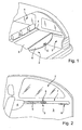
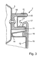
- a motor vehicle after the Fig. 1 and 2 represents a passenger car whose motor vehicle interior 1 is divided into a provided in a front region of the passenger compartment and in a rear side provided cargo space 2.
- the cargo space 2 is open in the passenger compartment.
- the cargo space 2 is seen in the normal direction of travel bounded to the front by a backrest assembly of a rear bench seat.
- On opposite sides of the cargo space 2 is bounded by two side walls 3 and to the rear closes the load compartment 2 on a tailgate, not shown.
- a cassette housing 4 is provided which extends over the entire width of the cargo space 2 in the vehicle transverse direction.
- a winding shaft is rotatably mounted, on which a flexible sheet 5 is held up and unwound.
- the flexible sheet 5 is used in the illustrated embodiment for approximately horizontal coverage of the cargo space 2 and is made of an opaque, single or multi-layer web material.
- the web material preferably has at least one web layer of a textile fabric or knitted fabric, which is made of plastic and / or textile fibers.
- the winding shaft is loaded in the winding by a coil spring assembly, so that a permanent tensile force is exerted on the fabric 5 in the winding.
- a dimensionally stable extension profile 6 is provided, which in the embodiment according to Fig. 1 With a Kont society is provided, which is tuned to the inner contour of the cargo space in the rear area.
- the contour part is provided with a grip element G, which allows grasping the pull-out profile 6 and thus of the fabric 5 by hand.
- the pull-out profile 6 extends over the entire width of the loading space 2 and protrudes laterally at its opposite side areas by guide elements 9 in the form of guide extensions over a respective side edge of the sheet 5, i. transversely to the extension direction of the fabric 5 to the outside.
- These guide elements 9 are guided longitudinally displaceable on each side of the vehicle in corresponding guides 7 of the respective side wall 3 of the motor vehicle interior.
- the guides 7 have a length which corresponds approximately to the Ausziehweg the Auszugprofils 6 between a wound-on rest position of the fabric 5 and the extended protective position of the fabric 5, in which the fabric 5 pulled out with its pull-6 to the rear of the cargo space 2 and there is fixed.
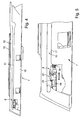
- Each guide 7 is designed as a multipart guide profile ( Fig. 3 to 5 ) and is attached to the body side of the respective side wall 3.
- the respective guide 7 is attached directly to a side part of the Karosseriag structure of the side wall 3, to allow a stable and preferably crash-proof connection of the guide 7 to the vehicle body.
- the three-part construction is formed by three profile parts 15, 12, 10, which extend in one piece continuously over the entire guide length of the guide 7 for the extension profile 9 and transversely to the guide direction for the extension profile 9 are interconnected.
- a first, to the loading space center facing profile part 15 serves as a guide profile and forms the middle of the loading space facing the front end of the guide 7.
- a middle profile part 12 serves as a functional profile and has a C-like to the center of the cargo compartment open functional groove 13, which extends over the entire guide length of the extension profile 6 extends.
- serving as a guide profile first profile part 15 has in its upper region as a guide surface on a web-like Gleitprofiltechnik 17, which partially covers the openjansnut 13 over its entire length.
- the web-like Gleitprofil réelle 17 is formed by a hook-like manner to the function groove 13 outwardly curved profile cross section, the width of which is substantially smaller than the depth of thejansnut 13 - seen in the horizontal direction.
- All profile parts 10, 12, 15 are preferably made of suitable plastic materials. But it is also possible to produce one or more profile parts from other suitable materials.
- the third, directed to the outside of the body support structure profile part 10 is designed as a C-shaped stiffening profile and has two profile legs 11 which flank the function groove 13 and thus the corresponding profile section of the profile member 12 above and below.
- This stiffening profile it is possible to carry out the profile part 12, which serves as a functional profile, relatively thin.
- the profile part 10 serving as a stiffening profile is fixedly connected to corresponding support structure sections of the vehicle body by means of corresponding fastening elements.
- the middle profile part 12 has a continuous profile web below the functional groove 13, which is also supported on a corresponding support structure portion of the vehicle body and is firmly connected by means of appropriate fasteners.
- the front profile part 15 is provided with a web portion 16 at the level of the support web 14, which projects into the V-shaped hollow profiled support web 14. It is possible to provide at the level of the web portion 16 and at the level of the support web 14 common fastening means which connect both profile parts with the corresponding support structure portion of the vehicle body. Below the Gleitprofiltechnik 17, the front side of the profile part 15, which is turned to the loading space center, a substantially smooth-surfaced, in the assembled state vertically oriented facing. This can be integrated spatially and / or optically in a side panel of the side wall 3.
- the individual profile parts, the shell-shaped in or joined together, can be connected to each other by mechanical locking means or by cohesive connection means.
- the mechanical locking means are preferably integrally formed on the corresponding profile parts.
- the gap remaining between the sliding profile 17 and an upper edge of the functional groove 13 is matched to the height of the respective guide element 9 of the pull-out profile 6 in such a way that it can be moved longitudinally with little play in the guide slot.
- the guide element 9 has a width which allows it to engage in almost the entire horizontal depth of the functional groove 13.
- a sliding portion not shown, slides the guide member 9 on the Gleitprofiltechnik 17.
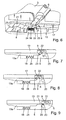
- the guide member 9 is provided with a locking means in the form of a locking element 22 which is limited pivotally mounted about a pivot axis S on the guide element 9.
- the pivot axis S extends in the longitudinal direction of the extension profile 6 and thus transversely to the longitudinal extent of the sheet 5.
- the guide element 9 is recessed in the region of the locking element 22 such that the locking element 22 can dive flush into this recess spatially.
- the guide element 9, as shown by the Fig. 6 to 9 is recognizable, an approximately rectangular cross section.
- the locking element 22 is embodied as a parallelepiped and has a wedge-shaped tip at one end face and a dovetail or fork-like profiling 23 at the opposite end face. In unloaded rest position protrudes the locking element 22 according to 6 and 7 obliquely downward, with its wedge-shaped tip is supported on a corresponding wall of the recess of the guide element 9.
- the width of the locking element 22 and in the rest position down over the guide member 9 projecting depth are matched to a recessed groove portion 13a of thejansnut 13 that the locking element 22 are preferably moved in the obliquely directed position in the recessed groove portion 13a without sliding attachment can.
- the locking element 22 protrudes into the recessed groove section 13a without contact in this unloaded rest position supported on the guide element 9.
- the sliding portion of the guide element 9 rests on the sliding profile 17 of the profile part 15 during the entire movement.
- a recessed recess 24 in which a blocking element 8 is arranged.
- the blocking element 8 has a width that is advantageously not greater than the width of the recessed groove portion 13a.
- the blocking element is designed to be shorter than the length of the recess 24, so that it is held limited longitudinally movable in the recess 24.
- the blocking element 8 is pressure-loaded by a return spring assembly 18 in the extension direction of the sheet 5 and the pull-6, so that it is kept pressed in the unloaded position permanently against a provided in the recess 24 stop 19.
- the blocking element 8 is therefore in the longitudinal direction of the recessed groove portion limited longitudinally movably mounted, wherein the blocking element 8 is arranged parallel below the groove portion 13a.
- the height of the blocking element 8 is matched to the recess 24 such that an upper edge of the blocking element 8 is at least substantially flush with the plane defined by the groove portion 13a.
- the blocking element 8 has a blocking lug 20 on a top leading edge region seen in the drawing-out direction of the fabric, which protrudes approximately horizontally toward the rear of the vehicle.
- the blocking lug 20 is matched in its contour to the dovetail or fork-like design of the locking element 22 in such a way that the forked or dovetailed head 23 of the locking element 22 can surround the latching lug 20 substantially flush.
- the locking nose 20 is then provided with a slide-on surface 21 on which the locking element 22 can raise itself out of its unloaded rest position as soon as the slide-out profile with the corresponding guide elements 9 slides over the respective blocking element 8.
- the locking element 22 is spring-loaded in the direction of its unloaded rest position, so that the locking element 22 automatically moves back to its inclined position after passing over the sliding surface 21, as soon as the forced operation is canceled by the blocking element 8 or Aufgleit Chemistry 21.
- the return force of the coil spring assembly which acts on the fabric 5, then inevitably pulls the locking element against the locking lug ( Fig. 9 ), so that a positive locking of the pull-out profile and the guide elements 9 in the extended protective position of the fabric 5 is achieved.
- Each of the two guide elements 9 is provided with a corresponding locking element 22, which are connected to each other via a synchronizing means such as a transversely through the extension profile 6 extending transmission rod or the like to transmit movement.
- Both locking elements are jointly pivotable by an actuator in the region of the grip part G, so that upon actuation of the actuating element both locking elements can be swung out of their unloaded rest position at the same time.
- the locking elements 22 may be associated with a common return spring, which loads both locking elements simultaneously and at equal amounts.
- the locking elements 22 also have a common pivot axis S, wherein the transmission linkage is preferably designed as over the entire length of the extension profile continuous shaft, at the opposite ends of the corresponding locking elements are arranged.
- the actuating element in the region of the grip part G can then preferably act directly on this shaft. In the same way, the return spring arrangement can act directly on this wave.
- the compression spring 18 in each guide 7 is chosen in its spring force to be greater than the return force of the coil spring assembly acting on the sheet.
- the compression spring 18, which holds each blocking element 8 pressed in the direction of the stop 19, thus serves in addition to keep the fabric taut in the extended protective position.
- the longitudinal mobility of the blocking element 8 and the corresponding compression spring 18 is used to compensate for length tolerances of the sheet and installation tolerances of the cassette housing 4 and the guides.
Landscapes
- Engineering & Computer Science (AREA)
- Mechanical Engineering (AREA)
- Vehicle Step Arrangements And Article Storage (AREA)
- Body Structure For Vehicles (AREA)
- Vehicle Interior And Exterior Ornaments, Soundproofing, And Insulation (AREA)
- Fittings On The Vehicle Exterior For Carrying Loads, And Devices For Holding Or Mounting Articles (AREA)
Claims (11)
- Intérieur de véhicule automobile comprenant un compartiment qui peut être recouvert par une structure plane flexible dans une position de protection déployée, la structure plane étant pourvue, au niveau de sa zone d'extrémité frontale avant dans le sens de déploiement, d'un profilé de déploiement indéformable qui est logé sur les côtés opposés dans des guidages situés côté véhicule automobile de manière à pouvoir coulisser le long desdits guidages, et qui dans au moins une position de déploiement peut être arrêté au moyen d'au moins un élément de blocage, caractérisé en ce que chaque guidage (7) situé côté véhicule automobile est constitué de plusieurs pièces profilées (15, 12, 10) qui se superposent au moins par sections transversalement par rapport au sens de guidage, et qui s'étendent dans le sens de guidage respectivement d'un seul tenant sur la longueur du guidage (7).
- Intérieur de véhicule automobile selon la revendication 1, caractérisé en ce que chaque guidage (7) comporte une surface de guidage (17) ouverte en direction du milieu d'un véhicule et parallèlement derrière la surface de guidage (17) une rainure fonctionnelle (13, 13a) plus profonde par rapport à la surface de guidage, le au moins un élément de blocage (8) étant associé à ladite rainure.
- Intérieur de véhicule automobile selon la revendication 2, caractérisé en ce que l'élément de blocage (8) est agencé dans un évidement (24) plus profond de la rainure fonctionnelle (13, 13a), et en ce qu'un élément de verrouillage (22) logé de manière mobile entre une position de déblocage et une position de blocage est associé au profilé de déploiement (6) pour chaque élément de blocage (8), ledit élément de verrouillage dans la position de blocage venant en prise derrière l'élément de blocage (8) par concordance de forme.
- Intérieur de véhicule automobile selon la revendication 3, caractérisé en ce que les éléments de verrouillage (22) peuvent être commandés de manière synchrone de part et d'autre du profilé de déploiement (6) par l'intermédiaire d'un organe d'actionnement commun.
- Intérieur de véhicule automobile selon l'une quelconque des revendications précédentes, caractérisé en ce que les éléments de blocage (8) peuvent être déplacés longitudinalement de manière limitée contre la force d'un ressort dans le sens de déplacement du profilé de déploiement (9).
- Intérieur de véhicule automobile selon l'une quelconque des revendications précédentes, caractérisé en ce que chaque élément de blocage (8) comporte sur son côté tourné vers la rainure fonctionnelle (13, 13a) un ergot de blocage (20), et en ce que l'élément de verrouillage associé (22) du profilé de déploiement (6) est logé à pivotement et est pourvu d'une tête (23) semblable à un crochet, laquelle est adaptée de telle manière à l'ergot de blocage (20) que dans la position de blocage elle entoure, au moins par sections, l'ergot de blocage (20).
- Intérieur de véhicule automobile selon la revendication 1, caractérisé en ce qu'une pièce profilée (15) servant de profilé de guidage, voisine de la structure plane flexible (5) comporte comme surface de guidage une surface de roulement (17) surélevée de manière similaire à une âme pour un appui coulissant d'une zone latérale (9) du profilé de déploiement (6).
- Intérieur de véhicule automobile selon la revendication 7, caractérisé en ce que le matériau de la pièce profilée (15) comporte un faible coefficient de frottement.
- Intérieur de véhicule automobile selon la revendication 1, caractérisé en ce qu'une autre pièce profilée (12) servant de profilé fonctionnel est pourvue d'une rainure fonctionnelle (13, 13a) disposée de manière plus profonde par rapport à la surface de roulement (17) de la première pièce profilée (15), l'évidement (24) pour l'élément de blocage étant prévu dans ladite rainure.
- Intérieur de véhicule automobile selon la revendication 1, caractérisé en ce qu'une troisième pièce profilée (10) flanquant l'autre pièce profilée (12) située en face de la première pièce profilée (15) est formée comme profilé de renforcement, qui soutient l'autre pièce profilée (12) dans la zone de la rainure fonctionnelle.
- Intérieur de véhicule automobile selon la revendication 1, caractérisé en ce que toutes les trois pièces profilées (10, 12, 15) sont jointes en forme de coque dans le sens transversal de la structure plane.
Priority Applications (1)
| Application Number | Priority Date | Filing Date | Title |
|---|---|---|---|
| EP07024092A EP1902901B1 (fr) | 2006-02-28 | 2007-02-02 | Habitacle de véhicule automobile doté d'une section d'espace |
Applications Claiming Priority (1)
| Application Number | Priority Date | Filing Date | Title |
|---|---|---|---|
| DE102006010114A DE102006010114A1 (de) | 2006-02-28 | 2006-02-28 | Kraftfahrzeuginnenraum mit einem Raumausschnitt |
Related Child Applications (1)
| Application Number | Title | Priority Date | Filing Date |
|---|---|---|---|
| EP07024092A Division EP1902901B1 (fr) | 2006-02-28 | 2007-02-02 | Habitacle de véhicule automobile doté d'une section d'espace |
Publications (2)
| Publication Number | Publication Date |
|---|---|
| EP1826064A1 EP1826064A1 (fr) | 2007-08-29 |
| EP1826064B1 true EP1826064B1 (fr) | 2008-04-23 |
Family
ID=38093353
Family Applications (2)
| Application Number | Title | Priority Date | Filing Date |
|---|---|---|---|
| EP07002278A Not-in-force EP1826064B1 (fr) | 2006-02-28 | 2007-02-02 | Intérieur de véhicule avec un compartiment |
| EP07024092A Not-in-force EP1902901B1 (fr) | 2006-02-28 | 2007-02-02 | Habitacle de véhicule automobile doté d'une section d'espace |
Family Applications After (1)
| Application Number | Title | Priority Date | Filing Date |
|---|---|---|---|
| EP07024092A Not-in-force EP1902901B1 (fr) | 2006-02-28 | 2007-02-02 | Habitacle de véhicule automobile doté d'une section d'espace |
Country Status (4)
| Country | Link |
|---|---|
| EP (2) | EP1826064B1 (fr) |
| AT (2) | ATE393058T1 (fr) |
| DE (3) | DE102006010114A1 (fr) |
| ES (1) | ES2304184T3 (fr) |
Families Citing this family (4)
| Publication number | Priority date | Publication date | Assignee | Title |
|---|---|---|---|---|
| DE102017223239A1 (de) * | 2017-12-19 | 2019-06-19 | Volkswagen Aktiengesellschaft | Innenmodul für einen Laderaum eines Fahrzeuges, Laderaumverkleidung sowie Herstellverfahren zum Herstellen eines Innenmoduls |
| CN111936352A (zh) * | 2018-03-12 | 2020-11-13 | 宝适汽车部件(太仓)有限公司 | 用于车辆内部空间的保护装置的形状稳定的拉出型材的解锁装置 |
| DE102018125299B3 (de) * | 2018-10-12 | 2020-01-02 | Macauto Industrial Co., Ltd. | Laderaumabdeckung für einen PKW |
| US11433821B2 (en) * | 2020-03-24 | 2022-09-06 | Honda Motor Co., Ltd. | Cargo area side panel assembly for a vehicle |
Family Cites Families (5)
| Publication number | Priority date | Publication date | Assignee | Title |
|---|---|---|---|---|
| DE10038842A1 (de) * | 2000-08-04 | 2002-02-28 | Butz Peter Verwaltung | Laderaumabdeckung für Kraftwagen, insbesondere für Kombinations-Personenkraftwagen |
| DE10113621C1 (de) * | 2001-03-20 | 2002-10-10 | Butz Peter Verwaltung | Laderaumabdeckung für Kraftwagen, wie für Kombinations-Personenkraftwagen od. dgl. |
| US20030062736A1 (en) * | 2001-09-28 | 2003-04-03 | Ulert Izaak A. | Secure cover for open cargo space |
| DE10348890A1 (de) * | 2003-10-15 | 2005-05-19 | Bos Gmbh & Co. Kg | Laderaumfunktionseinrichtung |
| DE10349936A1 (de) * | 2003-10-24 | 2005-06-16 | Bos Gmbh & Co. Kg | Laderaumabdeckung mit Verzurrmitteln |
-
2006
- 2006-02-28 DE DE102006010114A patent/DE102006010114A1/de not_active Withdrawn
-
2007
- 2007-02-02 AT AT07002278T patent/ATE393058T1/de not_active IP Right Cessation
- 2007-02-02 ES ES07002278T patent/ES2304184T3/es active Active
- 2007-02-02 DE DE502007003122T patent/DE502007003122D1/de active Active
- 2007-02-02 AT AT07024092T patent/ATE461078T1/de active
- 2007-02-02 DE DE502007000011T patent/DE502007000011D1/de active Active
- 2007-02-02 EP EP07002278A patent/EP1826064B1/fr not_active Not-in-force
- 2007-02-02 EP EP07024092A patent/EP1902901B1/fr not_active Not-in-force
Also Published As
| Publication number | Publication date |
|---|---|
| EP1826064A1 (fr) | 2007-08-29 |
| ATE461078T1 (de) | 2010-04-15 |
| EP1902901A1 (fr) | 2008-03-26 |
| EP1902901B1 (fr) | 2010-03-17 |
| DE502007003122D1 (de) | 2010-04-29 |
| ATE393058T1 (de) | 2008-05-15 |
| DE502007000011D1 (de) | 2008-06-05 |
| DE102006010114A1 (de) | 2007-08-30 |
| ES2304184T3 (es) | 2008-09-16 |
Similar Documents
| Publication | Publication Date | Title |
|---|---|---|
| DE10020212B4 (de) | Seitenfensterrollo mit Schlitzabdeckung | |
| DE3704816C2 (fr) | ||
| EP1524152B1 (fr) | Volet pour coffre | |
| EP1736335B1 (fr) | Store à enrouleur pour fenêtre arrière avec obturateur de fente par le tiroir | |
| EP1533158B1 (fr) | Système de store à enrouleur pour vitres latérals pourvu d'un pièce de contour de vitre | |
| WO1998024657A2 (fr) | Volet roulant cache-bagages a manipulation simplifiee | |
| DE10046553A1 (de) | Fensterrollo für gekrümmte oder nicht rechteckige Fahrzeugfenster | |
| EP2088021A2 (fr) | Recouvrement de pièces de guidage d'une porte coulissante de véhicule automobile | |
| DE10064513B4 (de) | Rollo | |
| EP1932700A2 (fr) | Store de fenêtre triangulaire pour véhicules automobiles | |
| EP2925548A2 (fr) | Système de toit pour véhicule automobile | |
| EP1800922B1 (fr) | Store à enrouler pour ombrage total d'une vitre arrière | |
| DE102007019858B4 (de) | Dachfensterrollo mit vorgespannten Gleitern | |
| EP0601454A1 (fr) | Store à enrouleur pour véhicule | |
| EP1826064B1 (fr) | Intérieur de véhicule avec un compartiment | |
| DE2260243A1 (de) | Passiver sicherheitsgurt fuer kraftfahrzeuge oder dergleichen | |
| DE3050964C2 (fr) | ||
| DE102014003440B3 (de) | Laderaumabdeckung für ein Fahrzeug | |
| DE4404618C2 (de) | Schiebelamellenabdeckung für ein Kraftfahrzeugdach | |
| DE102012215433B4 (de) | Rollosystem für einen Fahrzeuginnenraum | |
| EP1738942B1 (fr) | Store à enrouleur pour véhicule automobile muni d'une butée de contact fixée rigidement sur un actionneur | |
| DE202006018471U1 (de) | Kraftfahrzeuginnenraum mit einem Raumausschnitt | |
| DE60035756T2 (de) | Rollo, insbesondere für Autos, Schutzabdeckung und Montageverfahren hierzu | |
| DE19511066C1 (de) | Schiebehimmel für Kraftfahrzeugdächer | |
| DE4013157C1 (en) | Roller blind for car boot with releasable winder - has releasable locking protrusions, each axially next to long axis of winding shaft |
Legal Events
| Date | Code | Title | Description |
|---|---|---|---|
| PUAI | Public reference made under article 153(3) epc to a published international application that has entered the european phase |
Free format text: ORIGINAL CODE: 0009012 |
|
| AK | Designated contracting states |
Kind code of ref document: A1 Designated state(s): AT BE BG CH CY CZ DE DK EE ES FI FR GB GR HU IE IS IT LI LT LU LV MC NL PL PT RO SE SI SK TR |
|
| AX | Request for extension of the european patent |
Extension state: AL BA HR MK YU |
|
| 17P | Request for examination filed |
Effective date: 20070726 |
|
| GRAP | Despatch of communication of intention to grant a patent |
Free format text: ORIGINAL CODE: EPIDOSNIGR1 |
|
| GRAS | Grant fee paid |
Free format text: ORIGINAL CODE: EPIDOSNIGR3 |
|
| GRAA | (expected) grant |
Free format text: ORIGINAL CODE: 0009210 |
|
| AK | Designated contracting states |
Kind code of ref document: B1 Designated state(s): AT BE BG CH CY CZ DE DK EE ES FI FR GB GR HU IE IS IT LI LT LU LV MC NL PL PT RO SE SI SK TR |
|
| REG | Reference to a national code |
Ref country code: GB Ref legal event code: FG4D Free format text: NOT ENGLISH |
|
| AKX | Designation fees paid |
Designated state(s): AT BE BG CH CY CZ DE DK EE ES FI FR GB GR HU IE IS IT LI LT LU LV MC NL PL PT RO SE SI SK TR |
|
| REG | Reference to a national code |
Ref country code: CH Ref legal event code: EP |
|
| REF | Corresponds to: |
Ref document number: 502007000011 Country of ref document: DE Date of ref document: 20080605 Kind code of ref document: P |
|
| REG | Reference to a national code |
Ref country code: IE Ref legal event code: FG4D Free format text: LANGUAGE OF EP DOCUMENT: GERMAN |
|
| REG | Reference to a national code |
Ref country code: SE Ref legal event code: TRGR |
|
| REG | Reference to a national code |
Ref country code: ES Ref legal event code: FG2A Ref document number: 2304184 Country of ref document: ES Kind code of ref document: T3 |
|
| PG25 | Lapsed in a contracting state [announced via postgrant information from national office to epo] |
Ref country code: SI Free format text: LAPSE BECAUSE OF FAILURE TO SUBMIT A TRANSLATION OF THE DESCRIPTION OR TO PAY THE FEE WITHIN THE PRESCRIBED TIME-LIMIT Effective date: 20080423 |
|
| NLV1 | Nl: lapsed or annulled due to failure to fulfill the requirements of art. 29p and 29m of the patents act | ||
| PG25 | Lapsed in a contracting state [announced via postgrant information from national office to epo] |
Ref country code: BG Free format text: LAPSE BECAUSE OF FAILURE TO SUBMIT A TRANSLATION OF THE DESCRIPTION OR TO PAY THE FEE WITHIN THE PRESCRIBED TIME-LIMIT Effective date: 20080723 Ref country code: NL Free format text: LAPSE BECAUSE OF FAILURE TO SUBMIT A TRANSLATION OF THE DESCRIPTION OR TO PAY THE FEE WITHIN THE PRESCRIBED TIME-LIMIT Effective date: 20080423 Ref country code: FI Free format text: LAPSE BECAUSE OF FAILURE TO SUBMIT A TRANSLATION OF THE DESCRIPTION OR TO PAY THE FEE WITHIN THE PRESCRIBED TIME-LIMIT Effective date: 20080423 Ref country code: PT Free format text: LAPSE BECAUSE OF FAILURE TO SUBMIT A TRANSLATION OF THE DESCRIPTION OR TO PAY THE FEE WITHIN THE PRESCRIBED TIME-LIMIT Effective date: 20080923 |
|
| PG25 | Lapsed in a contracting state [announced via postgrant information from national office to epo] |
Ref country code: PL Free format text: LAPSE BECAUSE OF FAILURE TO SUBMIT A TRANSLATION OF THE DESCRIPTION OR TO PAY THE FEE WITHIN THE PRESCRIBED TIME-LIMIT Effective date: 20080423 Ref country code: LV Free format text: LAPSE BECAUSE OF FAILURE TO SUBMIT A TRANSLATION OF THE DESCRIPTION OR TO PAY THE FEE WITHIN THE PRESCRIBED TIME-LIMIT Effective date: 20080423 |
|
| REG | Reference to a national code |
Ref country code: IE Ref legal event code: FD4D |
|
| PG25 | Lapsed in a contracting state [announced via postgrant information from national office to epo] |
Ref country code: IS Free format text: LAPSE BECAUSE OF FAILURE TO SUBMIT A TRANSLATION OF THE DESCRIPTION OR TO PAY THE FEE WITHIN THE PRESCRIBED TIME-LIMIT Effective date: 20080823 |
|
| ET | Fr: translation filed | ||
| PG25 | Lapsed in a contracting state [announced via postgrant information from national office to epo] |
Ref country code: DK Free format text: LAPSE BECAUSE OF FAILURE TO SUBMIT A TRANSLATION OF THE DESCRIPTION OR TO PAY THE FEE WITHIN THE PRESCRIBED TIME-LIMIT Effective date: 20080423 Ref country code: IE Free format text: LAPSE BECAUSE OF FAILURE TO SUBMIT A TRANSLATION OF THE DESCRIPTION OR TO PAY THE FEE WITHIN THE PRESCRIBED TIME-LIMIT Effective date: 20080423 Ref country code: LT Free format text: LAPSE BECAUSE OF FAILURE TO SUBMIT A TRANSLATION OF THE DESCRIPTION OR TO PAY THE FEE WITHIN THE PRESCRIBED TIME-LIMIT Effective date: 20080423 Ref country code: CZ Free format text: LAPSE BECAUSE OF FAILURE TO SUBMIT A TRANSLATION OF THE DESCRIPTION OR TO PAY THE FEE WITHIN THE PRESCRIBED TIME-LIMIT Effective date: 20080423 |
|
| PG25 | Lapsed in a contracting state [announced via postgrant information from national office to epo] |
Ref country code: SK Free format text: LAPSE BECAUSE OF FAILURE TO SUBMIT A TRANSLATION OF THE DESCRIPTION OR TO PAY THE FEE WITHIN THE PRESCRIBED TIME-LIMIT Effective date: 20080423 Ref country code: RO Free format text: LAPSE BECAUSE OF FAILURE TO SUBMIT A TRANSLATION OF THE DESCRIPTION OR TO PAY THE FEE WITHIN THE PRESCRIBED TIME-LIMIT Effective date: 20080423 |
|
| PLBE | No opposition filed within time limit |
Free format text: ORIGINAL CODE: 0009261 |
|
| STAA | Information on the status of an ep patent application or granted ep patent |
Free format text: STATUS: NO OPPOSITION FILED WITHIN TIME LIMIT |
|
| 26N | No opposition filed |
Effective date: 20090126 |
|
| PG25 | Lapsed in a contracting state [announced via postgrant information from national office to epo] |
Ref country code: EE Free format text: LAPSE BECAUSE OF FAILURE TO SUBMIT A TRANSLATION OF THE DESCRIPTION OR TO PAY THE FEE WITHIN THE PRESCRIBED TIME-LIMIT Effective date: 20080423 |
|
| BERE | Be: lapsed |
Owner name: BOS G.M.B.H. & CO. KG Effective date: 20090228 |
|
| PG25 | Lapsed in a contracting state [announced via postgrant information from national office to epo] |
Ref country code: IT Free format text: LAPSE BECAUSE OF FAILURE TO SUBMIT A TRANSLATION OF THE DESCRIPTION OR TO PAY THE FEE WITHIN THE PRESCRIBED TIME-LIMIT Effective date: 20080423 |
|
| PG25 | Lapsed in a contracting state [announced via postgrant information from national office to epo] |
Ref country code: MC Free format text: LAPSE BECAUSE OF NON-PAYMENT OF DUE FEES Effective date: 20090228 |
|
| EUG | Se: european patent has lapsed | ||
| REG | Reference to a national code |
Ref country code: FR Ref legal event code: ST Effective date: 20091030 |
|
| PG25 | Lapsed in a contracting state [announced via postgrant information from national office to epo] |
Ref country code: BE Free format text: LAPSE BECAUSE OF NON-PAYMENT OF DUE FEES Effective date: 20090228 |
|
| REG | Reference to a national code |
Ref country code: ES Ref legal event code: FD2A Effective date: 20090203 |
|
| PG25 | Lapsed in a contracting state [announced via postgrant information from national office to epo] |
Ref country code: FR Free format text: LAPSE BECAUSE OF NON-PAYMENT OF DUE FEES Effective date: 20090302 |
|
| PG25 | Lapsed in a contracting state [announced via postgrant information from national office to epo] |
Ref country code: AT Free format text: LAPSE BECAUSE OF NON-PAYMENT OF DUE FEES Effective date: 20090202 |
|
| PG25 | Lapsed in a contracting state [announced via postgrant information from national office to epo] |
Ref country code: ES Free format text: LAPSE BECAUSE OF NON-PAYMENT OF DUE FEES Effective date: 20090203 |
|
| PG25 | Lapsed in a contracting state [announced via postgrant information from national office to epo] |
Ref country code: GR Free format text: LAPSE BECAUSE OF FAILURE TO SUBMIT A TRANSLATION OF THE DESCRIPTION OR TO PAY THE FEE WITHIN THE PRESCRIBED TIME-LIMIT Effective date: 20080724 |
|
| PG25 | Lapsed in a contracting state [announced via postgrant information from national office to epo] |
Ref country code: LU Free format text: LAPSE BECAUSE OF NON-PAYMENT OF DUE FEES Effective date: 20090202 |
|
| PG25 | Lapsed in a contracting state [announced via postgrant information from national office to epo] |
Ref country code: SE Free format text: LAPSE BECAUSE OF NON-PAYMENT OF DUE FEES Effective date: 20090203 |
|
| PG25 | Lapsed in a contracting state [announced via postgrant information from national office to epo] |
Ref country code: HU Free format text: LAPSE BECAUSE OF FAILURE TO SUBMIT A TRANSLATION OF THE DESCRIPTION OR TO PAY THE FEE WITHIN THE PRESCRIBED TIME-LIMIT Effective date: 20081024 |
|
| PG25 | Lapsed in a contracting state [announced via postgrant information from national office to epo] |
Ref country code: TR Free format text: LAPSE BECAUSE OF FAILURE TO SUBMIT A TRANSLATION OF THE DESCRIPTION OR TO PAY THE FEE WITHIN THE PRESCRIBED TIME-LIMIT Effective date: 20080423 |
|
| PG25 | Lapsed in a contracting state [announced via postgrant information from national office to epo] |
Ref country code: CY Free format text: LAPSE BECAUSE OF FAILURE TO SUBMIT A TRANSLATION OF THE DESCRIPTION OR TO PAY THE FEE WITHIN THE PRESCRIBED TIME-LIMIT Effective date: 20080423 |
|
| REG | Reference to a national code |
Ref country code: CH Ref legal event code: PL |
|
| GBPC | Gb: european patent ceased through non-payment of renewal fee |
Effective date: 20110202 |
|
| PG25 | Lapsed in a contracting state [announced via postgrant information from national office to epo] |
Ref country code: CH Free format text: LAPSE BECAUSE OF NON-PAYMENT OF DUE FEES Effective date: 20110228 Ref country code: LI Free format text: LAPSE BECAUSE OF NON-PAYMENT OF DUE FEES Effective date: 20110228 |
|
| PG25 | Lapsed in a contracting state [announced via postgrant information from national office to epo] |
Ref country code: GB Free format text: LAPSE BECAUSE OF NON-PAYMENT OF DUE FEES Effective date: 20110202 |
|
| PGFP | Annual fee paid to national office [announced via postgrant information from national office to epo] |
Ref country code: DE Payment date: 20170223 Year of fee payment: 11 |
|
| REG | Reference to a national code |
Ref country code: DE Ref legal event code: R119 Ref document number: 502007000011 Country of ref document: DE |
|
| PG25 | Lapsed in a contracting state [announced via postgrant information from national office to epo] |
Ref country code: DE Free format text: LAPSE BECAUSE OF NON-PAYMENT OF DUE FEES Effective date: 20180901 |