EP1526063B1 - Engin de travaux - Google Patents
Engin de travaux Download PDFInfo
- Publication number
- EP1526063B1 EP1526063B1 EP03717640A EP03717640A EP1526063B1 EP 1526063 B1 EP1526063 B1 EP 1526063B1 EP 03717640 A EP03717640 A EP 03717640A EP 03717640 A EP03717640 A EP 03717640A EP 1526063 B1 EP1526063 B1 EP 1526063B1
- Authority
- EP
- European Patent Office
- Prior art keywords
- hoses
- main body
- traction
- work machine
- material member
- Prior art date
- Legal status (The legal status is an assumption and is not a legal conclusion. Google has not performed a legal analysis and makes no representation as to the accuracy of the status listed.)
- Expired - Lifetime
Links
- 239000000463 material Substances 0.000 claims description 35
- 239000012530 fluid Substances 0.000 claims description 13
- 238000010276 construction Methods 0.000 claims description 7
- 230000001012 protector Effects 0.000 claims description 5
- 239000010720 hydraulic oil Substances 0.000 description 6
- 230000000694 effects Effects 0.000 description 3
- 238000003780 insertion Methods 0.000 description 3
- 230000037431 insertion Effects 0.000 description 3
- 238000007599 discharging Methods 0.000 description 2
- 239000004743 Polypropylene Substances 0.000 description 1
- 238000009412 basement excavation Methods 0.000 description 1
- 239000013013 elastic material Substances 0.000 description 1
- 229920001971 elastomer Polymers 0.000 description 1
- 238000012856 packing Methods 0.000 description 1
- -1 polypropylene Polymers 0.000 description 1
- 229920001155 polypropylene Polymers 0.000 description 1
- 239000005060 rubber Substances 0.000 description 1
- 229920003051 synthetic elastomer Polymers 0.000 description 1
- 239000005061 synthetic rubber Substances 0.000 description 1
- 238000004804 winding Methods 0.000 description 1
Images


Classifications
-
- F—MECHANICAL ENGINEERING; LIGHTING; HEATING; WEAPONS; BLASTING
- F16—ENGINEERING ELEMENTS AND UNITS; GENERAL MEASURES FOR PRODUCING AND MAINTAINING EFFECTIVE FUNCTIONING OF MACHINES OR INSTALLATIONS; THERMAL INSULATION IN GENERAL
- F16L—PIPES; JOINTS OR FITTINGS FOR PIPES; SUPPORTS FOR PIPES, CABLES OR PROTECTIVE TUBING; MEANS FOR THERMAL INSULATION IN GENERAL
- F16L11/00—Hoses, i.e. flexible pipes
- F16L11/04—Hoses, i.e. flexible pipes made of rubber or flexible plastics
- F16L11/10—Hoses, i.e. flexible pipes made of rubber or flexible plastics with reinforcements not embedded in the wall
-
- E—FIXED CONSTRUCTIONS
- E02—HYDRAULIC ENGINEERING; FOUNDATIONS; SOIL SHIFTING
- E02F—DREDGING; SOIL-SHIFTING
- E02F3/00—Dredgers; Soil-shifting machines
- E02F3/04—Dredgers; Soil-shifting machines mechanically-driven
- E02F3/28—Dredgers; Soil-shifting machines mechanically-driven with digging tools mounted on a dipper- or bucket-arm, i.e. there is either one arm or a pair of arms, e.g. dippers, buckets
- E02F3/30—Dredgers; Soil-shifting machines mechanically-driven with digging tools mounted on a dipper- or bucket-arm, i.e. there is either one arm or a pair of arms, e.g. dippers, buckets with a dipper-arm pivoted on a cantilever beam, i.e. boom
- E02F3/32—Dredgers; Soil-shifting machines mechanically-driven with digging tools mounted on a dipper- or bucket-arm, i.e. there is either one arm or a pair of arms, e.g. dippers, buckets with a dipper-arm pivoted on a cantilever beam, i.e. boom working downwardly and towards the machine, e.g. with backhoes
- E02F3/325—Backhoes of the miniature type
-
- E—FIXED CONSTRUCTIONS
- E02—HYDRAULIC ENGINEERING; FOUNDATIONS; SOIL SHIFTING
- E02F—DREDGING; SOIL-SHIFTING
- E02F9/00—Component parts of dredgers or soil-shifting machines, not restricted to one of the kinds covered by groups E02F3/00 - E02F7/00
- E02F9/02—Travelling-gear, e.g. associated with slewing gears
- E02F9/024—Travelling-gear, e.g. associated with slewing gears with laterally or vertically adjustable wheels or tracks
-
- E—FIXED CONSTRUCTIONS
- E02—HYDRAULIC ENGINEERING; FOUNDATIONS; SOIL SHIFTING
- E02F—DREDGING; SOIL-SHIFTING
- E02F9/00—Component parts of dredgers or soil-shifting machines, not restricted to one of the kinds covered by groups E02F3/00 - E02F7/00
- E02F9/20—Drives; Control devices
- E02F9/22—Hydraulic or pneumatic drives
- E02F9/2264—Arrangements or adaptations of elements for hydraulic drives
- E02F9/2275—Hoses and supports therefor and protection therefor
Definitions
- the present invention relates to a work machine which has a traction device at each lateral side of the main body of the machine.
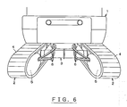
- Figs. 6 and 7 show a work machine, which is a hydraulic excavator or the like.
- the work machine has a main body 1 and traction devices 2.
- the traction devices 2 are respectively disposed at the two widthwise sides of the main body 1.
- the main body 1 is provided with a width changing device 3 for changing the widthwise positions of the traction devices 2 with respect to the main body 1.
- the width changing device 3 serves to increase the widthwise distance between the traction devices 2 with respect to the width of the main body 1 in order to ensure the stability during operation of the work machine, and reduce said widthwise distance in order to reduce the distance by which each traction device 2 projects outward from the widthwise side of the work machine 1.
- Each traction device 2 includes a traction motor 5 for driving a crawler belt 4. Connected to each traction motor 5 are a plurality of hoses 6 for supply and discharge of hydraulic oil from a hydraulic pump through a control valve unit and other relevant components to the traction motor 5.
- the aforementioned hydraulic pump is mounted on the main body 1.
- the hoses 6 are normally connected to the traction motors 5 within the interior of the main body 1 and the traction devices 2.
- the hoses 6 are normally connected at the exterior of the main body 1 and the traction devices 2 in order to permit operations to change the widthwise distance between the traction devices 2.
- the length of the hoses 6 is so set as to permit increase of the widthwise distance between the traction devices 2. Therefore, when the widthwise distance between the traction devices 2 is reduced, the hoses 6 slack as shown in Fig. 6 . At that time, as each hose 6 has a tendency to contort, the hoses 6 connected to each traction motor 5 become distanced from one another. When the work machine is moving, a hose 6 that has displaced downward is prone to come into contact with an obstacle on the ground and may therefore become damaged.
- Fig. 7 shows a way to prevent each set of hoses 6 from becoming distanced from one another by securing the plurality of hoses 6 by means of bundling the hoses 6 with a plurality of bands 7 at nearly regular intervals with respect to the lengthwise direction of the hoses 6.
- examples of alternate means to secure the plurality of hoses 6 include ring-shaped springs and tapes. When using these alternate means, too, the hoses 6 are secured by being bundled with them in the same manner as when the bands 7 are used.
- an object of the invention is to provide a work machine which permits easier bundling of a plurality of hoses and ensures protection of the hoses by covering them.
- Another object of the invention is to provide a work machine which permits bundled hoses to move together with an operation to change the widthwise distance between the traction devices 2.
- the present invention provides a work machine comprising a main body and a traction device disposed at each lateral side of the main body and provided with at least one fluid pressure-operated device, a set of flexible hoses communicating between the main body and the or each fluid pressure-operated device of each traction device so that hydraulic fluid may be supplied to and discharged from the or each fluid pressure-operated device through said set of hoses, and a flexible tubular hose cover, forming a housing for each set of hoses which extends between the main body and each respective traction device; wherein: the or each hose cover has at least a double construction having a flexible first material member and a second material member that is more rigid than the first material member.
- hose covers which serve to connect the main body and fluid pressure-operated device(s) of each traction device 13, through a flexible tubular hose cover, it is possible to easily bundle the hoses and reliably cover the hoses to ensure their protection.
- the hose covers having this feature have both sufficient flexibility to cope with the slack of the hoses contained therein and the shape-retaining ability sufficient to retain said slack to prevent unnecessary further slacking.
- a work machine is characterized in that the first material member of each hose cover has a tubular shape and that the second material member is in the shape of a spiral formed around the cylindrical outer surface of the first material member.
- This feature of the invention facilitates insertion of hoses through each tubular first material member and also ensures, by means of the second material member, that the hose cover has the shape-retaining ability while having sufficient flexibility.
- a work machine is characterized in that main body-side outlets for drawing the hoses out of the main body are formed in the main body; traction device-side outlets for drawing the hoses out of the traction devices are respectively formed in the traction devices; and that protectors are attached respectively to the edges of the main body-side outlets and the traction device-side outlets.
- a work machine is provided with a width changing device for changing the distance between the traction devices in the direction of the width of the main body.
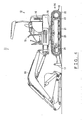
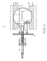
- Figs. 4 and 5 show a hydraulic excavator 11 as a work machine.
- the hydraulic excavator 11 has a main body 12 and traction devices 13.
- the traction devices 13 are respectively disposed at the two widthwise sides of the main body 12.
- the main body 12 comprises an undercarriage 14 and an upper structure 16 rotatably mounted on top of the undercarriage 14, with a revolving unit 15 therebetween.
- the undercarriage 14 is able to move by means of traction devices 13 provided at both sides of the undercarriage.
- a blade 17 is attached to the front end of the undercarriage 14.
- An operator's cab 18 is mounted on the top of the upper structure 16.
- a working unit 19 for excavation is attached to the front end of the upper structure 16.
- various components including an engine, a hydraulic pump adapted to be driven by the engine, and a control valve unit for controlling supply and discharge of hydraulic oil to and from various fluid pressure-operated devices of the work machine 11 are installed in the upper structure 16.
- the hydraulic oil is hydraulic fluid supplied from the aforementioned hydraulic pump.
- the aforementioned engine and hydraulic pump together constitute a hydraulic pressure source.
- Each traction device 13 has a track frame 21, around which an endless crawler belt 22 is extended.
- a sprocket for driving the crawler belt 22 is disposed at the rear end of the track frame 21.
- An idler 24 is rotatably disposed at the other end, i.e. the front end, of the track frame 21. The idler 24 is adapted to rotate in the manner of free rotation together with movement of the crawler belt 22.
- a plurality of guide rollers for guiding the crawler belt 22 are rotatably disposed at the middle of the track frame 21.
- the undercarriage 14 has a carriage platform 31, on top of which the revolving unit 15 is mounted.
- the aforementioned traction devices 13 are respectively disposed at the two widthwise sides of the carriage platform 31 and supported by a width changing device 32 so that the widthwise distance between the traction devices 13 can be increased or reduced.
- the width changing device 32 has a width changing support means 33 and a width changing drive means, which is not shown in the drawings.
- the width changing support means 33 serves to support the traction devices 13 and permits the traction devices 13 to move in the widthwise direction of the carriage platform 31 so that the distance between the traction devices is increased or reduced.
- the width changing drive means serves to move the traction devices 13 in the widthwise direction of the carriage platform 31, thereby increasing or reducing the distance between the traction devices.
- the width changing support means 33 comprises tubular supporting frames 34 and slide frames 35.
- the supporting frames 34 are respectively attached to the front and rear ends of the carriage platform 31 so as to extend in the widthwise direction of the carriage platform 31.
- Each slide frame 35 is slidably fitted through an open end of each supporting frame 34 and, in this state, attached to the track frame 21 of the corresponding traction device 13.
- the width changing drive means includes hydraulic cylinders (not shown), each of which is disposed between the carriage platform 31 and each respective track frame 21. As a result of operation of these hydraulic cylinders, the traction device 13 at each side of the carriage platform 31 is operated independently from each other in a widthwise direction so as to increase or reduce the distance from each other.
- Each traction device 13 is provided with a traction motor 39, which serves as a fluid pressure-operated device 38 to rotate the corresponding sprocket 23.
- the inner surface of each traction motor 39 is covered by a motor cover 40.
- the control valve unit of the main body 12 communicates with a swivel joint disposed at the center of revolving action.
- a plurality of flexible hoses 43 for supplying and discharging hydraulic oil to and from the swivel joint and the traction motor 39 of each traction device 13 extend between the swivel joint and the traction motor 39 so as to connect the swivel joint and the traction motor 39 from outside the main body 12 and the traction device 13.
- the length of the hoses 43 is so set as to permit increase of the widthwise distance between the traction devices 13.
- a main body-side outlet 44 for drawing said plurality of hoses 43 outside is formed in the rear panel of the revolution unit 15 of the main body, at a location to each one of the opposing side edges of the rear panel.
- a traction device-side outlet 45 for drawing the plurality of hoses 43 outside is formed in the motor cover 40 of each traction device 13.
- An elastic protector 46,47 for protecting the hoses 43 is attached to the edge of each respective main body-side outlet 44 and traction device-side outlet 45.
- the protectors 46,47 are made of an elastic material, such as grommet or rubber packing.
- each hose cover 48 is of an integral, double construction consisting of a first material member 49 and a second material member 50.
- the first material member 49 is made of a flexible material, such as synthetic rubber.
- the second material member 50 is made of a material which is more rigid than the first material member 49 and has the ability to retain the shape, such as polypropylene.
- the first material member 49 has a cylindrical shape with a smooth inner surface having no unevenness.
- the second material member 50 is in the shape of a spiral winding around the outer surface of the first material member 49 at a given pitch.
- Each hose cover 48 has an inner diameter such that a plurality of hoses 43 can be contained in a bundle inside the hose cover 48 and, in this state, permitted to move therein together with a width-changing movement of the corresponding traction device 13.
- the hose covers 48 have heat resistance sufficient to withstand the heat from the hoses 43, in which hydraulic oil flows with increasing temperature.
- Each hose cover 48 is flexible so as to easily cope with flexure of the hoses 43 contained therein.
- Each hose cover 48 ha an appropriate flexibility and also has the shape-retaining ability just sufficient to be able to prevent flexure of the hoses 43 due to their own weight or other unnecessary flexure of the hoses 43.
- the hoses 43 are inserted through a hose cover 48.
- the smooth inner surface of the hose cover 48 in other words, the inner surface of the first material member 49, which has no unevenness enables the easy insertion of the hoses 43. It is thus possible to bundle a plurality of hoses 43 easily merely by inserting them though a hose cover 48.
- each hose cover 48 As the portion of the hoses 43 located between the main body 12 and each traction device 13 and exposed to the outside is covered by the hose cover 48, the hose 43 are reliably protected, without the possibility of direct contact with an obstacle on the ground when the work machine is moving.
- the flexibility of each hose cover 48 enables the hose cover 48 to easily cope with flexure of the hoses 43, and the shape-retaining ability of the hose cover 38 maintains the hose 43 in an appropriate flexed shape while preventing unnecessary flexure of the hose 43.
- the appearance of the work machine 11 is improved.
- each hose cover 48 has the ability to retain its shape because of the second material member 50, it limits deformation of the cross sectional shape of each hose 43 due to movement of the hoses and remains gently curved to cope with the slack of the hoses 43.
- each hose cover 48 contains a plurality of hoses 43 that have merely been inserted through the hose cover 48, the hose cover 48 permits the hoses 43 to move therein together with a width changing movement of the corresponding traction device 13.
- the embodiment described above prevents damage to the hose covers 48.
- hoses 43 which serve to connect the main body 12 and each traction device 13 to each other, through a flexible tubular hose cover 48, it is possible to easily bundle the hoses and reliably cover the hoses to ensure their protection. Moreover, as the hoses 43 are permitted to move in the hose cover 48 together with a width changing movement of the traction device 13, the hose covers 48 is protected from damage.
- each hose cover 48 has both sufficient flexibility to cope with the slack of the hoses 43 contained therein and the shape-retaining ability sufficient to maintain said slack to prevent unnecessary further slacking.
- the first material member 49 of each hose cover 48 is formed in a tubular shape, and the second material member 50 is formed in the shape of a spiral around the cylindrical outer surface of the first material member 49. This feature facilitates insertion of hoses 43 through each tubular first material member 49 and also ensures, by means of the second material member 50, that the hose cover 48 has the shape-retaining ability while having sufficient flexibility.
- the protectors 46,47 disposed along the edges of the main body-side outlets 44 and the traction device-side outlets 45 prevent damage to the hoses 43, which may otherwise be caused by contact with the edge of a main body-side outlet 44 or a traction device-side outlet 45.
- each hose cover 48 may be formed as an integral body or, in an alternative structure, separate bodies to be assembled together afterwards.
- a double construction easily gives the hose covers 48 both flexibility and shape-retaining ability.
- the hose covers 48 may be of a single construction, provided that it is easy for the hose covers 48 to have both flexibility and shape-retaining ability.
- the hose covers 48 in order to ensure both flexibility and shape-retaining ability, it is also possible for the hose covers 48 to have a multi construction consisting of three or more walls.
- each traction device 13 has other fluid pressure-operated devices 38, examples of which include a hydraulic cylinder to apply a tensile force to the crawler belt 22. It is possible to achieve the same functions and effects for the hoses for supplying and discharging hydraulic oil to and from such a hydraulic cylinder by placing the hoses in a bundle inside the corresponding hose cover 48 together with the hoses 43 for the traction motor 39.
- the invention as has been explained above refers to the embodiment wherein the work machine 11 is provided with a width changing device 32. However, the invention is also applicable to a work machine 11 that is not provided with a width changing device 32; in cases where the hoses 43 connecting the main body to the traction devices 13 are exposed to the outside, the use of hose covers 48 provide the same functions and effects as described above.
- a work machine according to the invention is not limited to a hydraulic excavator; provided that it involves a work machine of which hoses connected to the main body and the traction devices are disposed externally, the invention is applicable to a wide range of work machines in order to solve problems arising from such disposition of the hoses.
Landscapes
- Engineering & Computer Science (AREA)
- General Engineering & Computer Science (AREA)
- Mining & Mineral Resources (AREA)
- Civil Engineering (AREA)
- Structural Engineering (AREA)
- Mechanical Engineering (AREA)
- Component Parts Of Construction Machinery (AREA)
- Motor Power Transmission Devices (AREA)
Abstract
Claims (4)
- Engin de travaux comprenant un corps principal (12) et un dispositif de traction (13) disposé de chaque côté latéral du corps principal et équipé d'au moins un dispositif actionné par pression d'un fluide (39),un ensemble de flexibles (43) communiquant entre le corps principal et le ou chaque dispositif actionné par pression d'un fluide (39) de chaque dispositif de traction, de sorte que du fluide hydraulique peut être amené au ou à chaque dispositif actionné par pression d'un fluide et évacué de celui-ci à travers cet ensemble de flexibles (43), etun gaine tubulaire souple pour flexibles (48) formant un logement pour chaque ensemble de flexibles (43) qui s'étend entre le corps principal et chaque dispositif de traction respectif,
dans lequel :la ou chaque gaine de flexibles (48) possède au moins une double construction comportant un premier élément souple de matériau (49) et un second élément de matériau (50) qui est plus rigide que le premier élément de matériau. - Engin de travaux selon la revendication 1, dans lequel :le premier élément de matériau (49) de chaque gaine de flexibles a une forme tubulaire, et le second élément de matériau (50) est en forme de spirale formée autour de la surface extérieure cylindrique du premier élément de matériau.
- Engin de travaux selon l'une quelconque des revendications 1 à 2, comprenant également :des sorties pour une extrémité de chaque ensemble de flexibles formées dans le corps principal ;des sorties pour l'autre extrémité de chaque ensemble de flexibles formées dans chaque dispositif de traction ; etdes dispositifs de protection (46, 47) fixés respectivement aux bords de chaque sortie.
- Engin de travaux selon l'une quelconque des revendications 1 à 3, comprenant également :un dispositif de changement de largeur (32) pour changer la distance entre les dispositifs de traction (13) dans la direction de la largeur du corps principal.
Applications Claiming Priority (3)
| Application Number | Priority Date | Filing Date | Title |
|---|---|---|---|
| JP2002217069 | 2002-07-25 | ||
| JP2002217069A JP2004060195A (ja) | 2002-07-25 | 2002-07-25 | 作業機械 |
| PCT/JP2003/004957 WO2004011322A1 (fr) | 2002-07-25 | 2003-04-18 | Engin de travaux |
Publications (3)
| Publication Number | Publication Date |
|---|---|
| EP1526063A1 EP1526063A1 (fr) | 2005-04-27 |
| EP1526063A4 EP1526063A4 (fr) | 2006-08-16 |
| EP1526063B1 true EP1526063B1 (fr) | 2008-02-27 |
Family
ID=31184594
Family Applications (1)
| Application Number | Title | Priority Date | Filing Date |
|---|---|---|---|
| EP03717640A Expired - Lifetime EP1526063B1 (fr) | 2002-07-25 | 2003-04-18 | Engin de travaux |
Country Status (5)
| Country | Link |
|---|---|
| US (1) | US7007416B2 (fr) |
| EP (1) | EP1526063B1 (fr) |
| JP (1) | JP2004060195A (fr) |
| DE (1) | DE60319384T2 (fr) |
| WO (1) | WO2004011322A1 (fr) |
Families Citing this family (9)
| Publication number | Priority date | Publication date | Assignee | Title |
|---|---|---|---|---|
| ES2241490B2 (es) * | 2004-04-06 | 2007-02-16 | Proyectos Y Tecnologia Sallen, S.L. | Robot autopropulsado para manipulacion de cargas explosivas. |
| JP4631639B2 (ja) * | 2005-09-27 | 2011-02-16 | カシオ計算機株式会社 | 時計装置 |
| ES1073757Y (es) | 2010-09-20 | 2011-05-06 | Proyectos Y Tecnologia Sallen S L | Robot telecomando para operaciones especiales |
| JP5741548B2 (ja) * | 2012-10-05 | 2015-07-01 | コベルコクレーン株式会社 | 建設機械の下部走行体 |
| JP6032712B2 (ja) * | 2013-11-28 | 2016-11-30 | キャタピラー エス エー アール エル | 走行装置および作業機械 |
| JP6588804B2 (ja) * | 2015-11-10 | 2019-10-09 | 株式会社日立建機ティエラ | ミニショベル |
| JP2022147167A (ja) * | 2021-03-23 | 2022-10-06 | ヤンマーホールディングス株式会社 | 建設機械 |
| JP7581124B2 (ja) * | 2021-05-24 | 2024-11-12 | ヤンマーホールディングス株式会社 | 建設機械 |
| DE102022125494A1 (de) * | 2022-10-04 | 2024-04-04 | Liebherr-Werk Nenzing Gmbh | Schutzvorrichtung und Arbeitsmaschine |
Family Cites Families (11)
| Publication number | Priority date | Publication date | Assignee | Title |
|---|---|---|---|---|
| GB889546A (en) * | 1959-09-22 | 1962-02-14 | Halifax Tool Co Ltd | Improvements in or relating to self-laying track vehicles |
| JPS548725A (en) | 1977-06-15 | 1979-01-23 | Osaka Prefecture | Deodorizing agent |
| JPS548725U (fr) * | 1977-06-21 | 1979-01-20 | ||
| DE3242066A1 (de) | 1982-11-13 | 1984-05-17 | Heidelberger Druckmaschinen Ag, 6900 Heidelberg | Kuehlwalze mit vorgewaehlten unterschiedlichen kuehlzonen |
| JPS59111854U (ja) * | 1983-01-17 | 1984-07-28 | 三菱農機株式会社 | 油圧シヨベル等の建設機械における高圧ホ−スのガ−ドスプリング |
| IT1217836B (it) * | 1988-06-17 | 1990-03-30 | Pierluigi Spalla | Macchina agricola semovente e polivalente |
| JPH05331877A (ja) | 1992-06-02 | 1993-12-14 | Kubota Corp | バックホウ |
| JPH0653884A (ja) | 1992-07-28 | 1994-02-25 | Tamura Electric Works Ltd | 伝言通知方法 |
| JPH0653884U (ja) * | 1992-12-28 | 1994-07-22 | トーフレ株式会社 | フレキシブルチューブ |
| JP3042239B2 (ja) * | 1993-01-29 | 2000-05-15 | 日立建機株式会社 | ラバーブッシング |
| JPH10238664A (ja) | 1997-02-27 | 1998-09-08 | Yoshihiro Fukuhara | 建築物の配管用防護装置 |
-
2002
- 2002-07-25 JP JP2002217069A patent/JP2004060195A/ja active Pending
-
2003
- 2003-04-18 EP EP03717640A patent/EP1526063B1/fr not_active Expired - Lifetime
- 2003-04-18 WO PCT/JP2003/004957 patent/WO2004011322A1/fr not_active Ceased
- 2003-04-18 US US10/514,141 patent/US7007416B2/en not_active Expired - Fee Related
- 2003-04-18 DE DE60319384T patent/DE60319384T2/de not_active Expired - Fee Related
Also Published As
| Publication number | Publication date |
|---|---|
| US20050126053A1 (en) | 2005-06-16 |
| US7007416B2 (en) | 2006-03-07 |
| WO2004011322A1 (fr) | 2004-02-05 |
| DE60319384T2 (de) | 2009-02-19 |
| EP1526063A1 (fr) | 2005-04-27 |
| JP2004060195A (ja) | 2004-02-26 |
| EP1526063A4 (fr) | 2006-08-16 |
| DE60319384D1 (de) | 2008-04-10 |
Similar Documents
| Publication | Publication Date | Title |
|---|---|---|
| EP1526063B1 (fr) | Engin de travaux | |
| EP3074301B1 (fr) | Dispositif de déplacement et machine de travail | |
| AU2017216571B2 (en) | Reel system within boom | |
| US9334622B2 (en) | Conduit support system | |
| CA2858180A1 (fr) | Appareil de pompe | |
| CN101070708A (zh) | 工程机械 | |
| JP4687683B2 (ja) | クローラ式作業機械の油圧配管構造 | |
| JP2011074605A (ja) | クローラ式走行装置 | |
| US20150000238A1 (en) | Work vehicles | |
| JP2006069492A (ja) | クローラ式走行装置 | |
| JP4640817B2 (ja) | 作業機の走行体 | |
| JP4406376B2 (ja) | 走行装置および作業機械 | |
| CN216010010U (zh) | 带锁紧装置的耐磨垫 | |
| US20250116084A1 (en) | Hoist rope protection | |
| JP2026036901A (ja) | ホースプロテクタ | |
| JP3550561B2 (ja) | クローラ式走行装置 | |
| JP3910837B2 (ja) | 作業機の油圧配管構造 | |
| JP3651620B2 (ja) | シールド掘進機のホースまたはケーブル収納装置 | |
| JP3031198B2 (ja) | クローラ式車両用配管 | |
| JP4246368B2 (ja) | 建設機械のトラックフレーム | |
| KR20140002072U (ko) | 굴삭기의 유압호스 가이드 구조 | |
| WO2016101026A1 (fr) | Appareil de pompage | |
| AU2013203052B2 (en) | Pump apparatus | |
| JP2000205283A (ja) | 旋回軸受の給脂構造 | |
| JP2011073494A (ja) | クローラ式走行装置 |
Legal Events
| Date | Code | Title | Description |
|---|---|---|---|
| PUAI | Public reference made under article 153(3) epc to a published international application that has entered the european phase |
Free format text: ORIGINAL CODE: 0009012 |
|
| 17P | Request for examination filed |
Effective date: 20050225 |
|
| AK | Designated contracting states |
Kind code of ref document: A1 Designated state(s): AT BE BG CH CY CZ DE DK EE ES FI FR GB GR HU IE IT LI LU MC NL PT RO SE SI SK TR |
|
| RBV | Designated contracting states (corrected) |
Designated state(s): DE FR GB IT |
|
| A4 | Supplementary search report drawn up and despatched |
Effective date: 20060718 |
|
| RIC1 | Information provided on ipc code assigned before grant |
Ipc: E02F 9/02 20060101ALI20060712BHEP Ipc: B62D 55/084 20060101ALI20060712BHEP Ipc: B62D 55/10 20060101AFI20040218BHEP |
|
| 17Q | First examination report despatched |
Effective date: 20070201 |
|
| GRAP | Despatch of communication of intention to grant a patent |
Free format text: ORIGINAL CODE: EPIDOSNIGR1 |
|
| GRAS | Grant fee paid |
Free format text: ORIGINAL CODE: EPIDOSNIGR3 |
|
| GRAA | (expected) grant |
Free format text: ORIGINAL CODE: 0009210 |
|
| AK | Designated contracting states |
Kind code of ref document: B1 Designated state(s): DE FR GB IT |
|
| REG | Reference to a national code |
Ref country code: GB Ref legal event code: FG4D |
|
| REF | Corresponds to: |
Ref document number: 60319384 Country of ref document: DE Date of ref document: 20080410 Kind code of ref document: P |
|
| PGFP | Annual fee paid to national office [announced via postgrant information from national office to epo] |
Ref country code: DE Payment date: 20080602 Year of fee payment: 6 |
|
| ET | Fr: translation filed | ||
| PGFP | Annual fee paid to national office [announced via postgrant information from national office to epo] |
Ref country code: IT Payment date: 20080424 Year of fee payment: 6 |
|
| PGFP | Annual fee paid to national office [announced via postgrant information from national office to epo] |
Ref country code: FR Payment date: 20080417 Year of fee payment: 6 |
|
| PGFP | Annual fee paid to national office [announced via postgrant information from national office to epo] |
Ref country code: GB Payment date: 20080429 Year of fee payment: 6 |
|
| PLBE | No opposition filed within time limit |
Free format text: ORIGINAL CODE: 0009261 |
|
| STAA | Information on the status of an ep patent application or granted ep patent |
Free format text: STATUS: NO OPPOSITION FILED WITHIN TIME LIMIT |
|
| 26N | No opposition filed |
Effective date: 20081128 |
|
| REG | Reference to a national code |
Ref country code: FR Ref legal event code: CD |
|
| GBPC | Gb: european patent ceased through non-payment of renewal fee |
Effective date: 20090418 |
|
| REG | Reference to a national code |
Ref country code: FR Ref legal event code: ST Effective date: 20091231 |
|
| PG25 | Lapsed in a contracting state [announced via postgrant information from national office to epo] |
Ref country code: DE Free format text: LAPSE BECAUSE OF NON-PAYMENT OF DUE FEES Effective date: 20091103 |
|
| PG25 | Lapsed in a contracting state [announced via postgrant information from national office to epo] |
Ref country code: GB Free format text: LAPSE BECAUSE OF NON-PAYMENT OF DUE FEES Effective date: 20090418 Ref country code: FR Free format text: LAPSE BECAUSE OF NON-PAYMENT OF DUE FEES Effective date: 20091222 |
|
| PG25 | Lapsed in a contracting state [announced via postgrant information from national office to epo] |
Ref country code: IT Free format text: LAPSE BECAUSE OF NON-PAYMENT OF DUE FEES Effective date: 20090418 |