EP1526221B1 - Stützfussanordnung für Arbeitsfahrzeug und Verfahren zur Steuerung dieser Anordnung. - Google Patents
Stützfussanordnung für Arbeitsfahrzeug und Verfahren zur Steuerung dieser Anordnung. Download PDFInfo
- Publication number
- EP1526221B1 EP1526221B1 EP04104930A EP04104930A EP1526221B1 EP 1526221 B1 EP1526221 B1 EP 1526221B1 EP 04104930 A EP04104930 A EP 04104930A EP 04104930 A EP04104930 A EP 04104930A EP 1526221 B1 EP1526221 B1 EP 1526221B1
- Authority
- EP
- European Patent Office
- Prior art keywords
- controller
- stabilizer
- joystick
- mode
- input device
- Prior art date
- Legal status (The legal status is an assumption and is not a legal conclusion. Google has not performed a legal analysis and makes no representation as to the accuracy of the status listed.)
- Expired - Lifetime
Links
- 239000003381 stabilizer Substances 0.000 title claims abstract description 215
- 238000000034 method Methods 0.000 title claims description 12
- 230000033001 locomotion Effects 0.000 claims abstract description 44
- 238000013016 damping Methods 0.000 claims abstract description 13
- 230000004044 response Effects 0.000 claims abstract description 9
- 230000008859 change Effects 0.000 claims description 14
- 238000012544 monitoring process Methods 0.000 claims description 8
- 230000010355 oscillation Effects 0.000 claims description 3
- 230000007935 neutral effect Effects 0.000 abstract description 38
- 239000012530 fluid Substances 0.000 description 13
- 230000006870 function Effects 0.000 description 7
- 238000004891 communication Methods 0.000 description 6
- 238000010586 diagram Methods 0.000 description 6
- 230000002441 reversible effect Effects 0.000 description 5
- 230000000630 rising effect Effects 0.000 description 4
- 230000005540 biological transmission Effects 0.000 description 3
- 238000002405 diagnostic procedure Methods 0.000 description 3
- 239000007787 solid Substances 0.000 description 3
- 230000007704 transition Effects 0.000 description 3
- 230000005355 Hall effect Effects 0.000 description 2
- 230000008901 benefit Effects 0.000 description 2
- 238000004140 cleaning Methods 0.000 description 2
- 230000000694 effects Effects 0.000 description 2
- 230000008569 process Effects 0.000 description 2
- 230000036461 convulsion Effects 0.000 description 1
- 230000009191 jumping Effects 0.000 description 1
- 238000004519 manufacturing process Methods 0.000 description 1
- 239000000463 material Substances 0.000 description 1
- 238000012986 modification Methods 0.000 description 1
- 230000004048 modification Effects 0.000 description 1
- 230000003287 optical effect Effects 0.000 description 1
- 230000003252 repetitive effect Effects 0.000 description 1
- 230000000284 resting effect Effects 0.000 description 1
- 238000005096 rolling process Methods 0.000 description 1
- 230000003068 static effect Effects 0.000 description 1
- 239000000725 suspension Substances 0.000 description 1
Images


Classifications
-
- E—FIXED CONSTRUCTIONS
- E02—HYDRAULIC ENGINEERING; FOUNDATIONS; SOIL SHIFTING
- E02F—DREDGING; SOIL-SHIFTING
- E02F9/00—Component parts of dredgers or soil-shifting machines, not restricted to one of the kinds covered by groups E02F3/00 - E02F7/00
- E02F9/20—Drives; Control devices
- E02F9/22—Hydraulic or pneumatic drives
- E02F9/2203—Arrangements for controlling the attitude of actuators, e.g. speed, floating function
-
- E—FIXED CONSTRUCTIONS
- E02—HYDRAULIC ENGINEERING; FOUNDATIONS; SOIL SHIFTING
- E02F—DREDGING; SOIL-SHIFTING
- E02F9/00—Component parts of dredgers or soil-shifting machines, not restricted to one of the kinds covered by groups E02F3/00 - E02F7/00
- E02F9/08—Superstructures; Supports for superstructures
- E02F9/085—Ground-engaging fitting for supporting the machines while working, e.g. outriggers, legs
Definitions
- the invention relates generally to work vehicles having stabilizers. More particularly, it relates to systems and methods for controlling the upward and downward motion of stabilizers.
- Vehicles such as those named above are of particular concern since they have arms that reach far out away from the vehicle chassis to either carry loads or to dig into the ground with ground engaging tools such as pavement breakers or buckets. Without a solid supporting foundation, these outwardly reaching arms might overbalance the vehicle resting on its tires.
- stabilizers that are slidingly or pivotally coupled to the chassis of the vehicle and extend outward therefrom to engage the ground.
- These stabilizers typically include an elongated member to which a broad ground-engaging pad is fixed at a free lower end thereof.
- stabilizers are commonly moved by actuators such as hydraulic cylinders that in turn are coupled to electrical, hydraulic or electro-hydraulic control circuits.
- the operator typically has a manual operator control or input device such as a switch, a lever or a joystick that he manipulates to extend or retract the cylinders, thereby lowering or raising the stabilizers.
- the stabilizer When the operator manipulates the controls to lower the stabilizer, the stabilizer typically slides or pivots downward and outward until the stabilizer pad engages the ground. Once in this position, the operator can lower the stabilizer a little further, lifting the chassis of the vehicle slightly, raising it a bit off its wheels.
- backhoes are often used to clean ditches on the side of the road. To do this cleaning, they are moved to a position facing the ditch. The stabilizers are then lowered to engage the ground. The operator then manipulates the backhoes' jointed arm (the boom, dipper and bucket) to scoop out material from the ditch.
- the process may repeat perhaps 20-100 times in the course of a day as the backhoe gradually goes down the ditch alongside the road cleaning excess dirt from it.
- the raising and lowering of the backhoe is time consuming during these operations.
- the operator must keep his hands on the stabilizer lift and lower controls the entire time the stabilizers are being lifted and lowered. This is time that he could spend rotating his seat to a forward facing position, shifting the vehicle into a drive gear and moving the vehicle a few feet down the road.
- he may keep the stabilizer controls in the lift position too long. On some vehicles with stabilizers, holding the control in the lift position after the stabilizer is already raised can cause the vehicle's engine to stall.
- the document GB-A-2 364 990 discloses a system and a method for automatically raising a stabilizer of a work vehicle, wherein the system comprises an input device configured to generate signals indicating a plurality of stabilizer rates of movement, an electronic controller configured to receive the signals from the input device and generate corresponding valve signals, at least one hydraulic valve coupled to the controller to move the stabilizer in response to the valve signals, wherein the controller has a mode of operation in which it automatically raises the stabilizer to a predetermined upper position.
- a system is provided according to claim 1.
- the controller may be configured to change from the first mode of operation to the second mode of operation based at least upon the operator's positioning of the input device.
- the controller may be configured to change from the first mode of operation to the second mode of operation based upon a period of time the input device is in any of several positions in a predetermined continuous range of positions, each of the several positions generating a different signal from the input device.
- the controller may be configured to exit the second mode of operation when the stabilizer reaches the predetermined upper position.
- the predetermined upper position may be indicated by a hydraulic pressure spike.
- the controller may be configured to monitor a sensor responsive to the hydraulic pressure spike.
- the controller may be configured to leave the second mode of operation at least after a predetermined period of time by closing the at least one valve.
- the controller may be configured to leave the second mode of operation at least when the operator does not release the input device.
- the system may further include a second input device configured to generate second signals indicating a plurality of stabilizer rates of movement for a second stabilizer; an electronic controller configured to receive the second signals from the second input device and generate corresponding second valve signals; and at least a second hydraulic valve coupled to the controller to move the second stabilizer in response to the second valve signals; wherein the controller is configured to control the stabilizer and the second stabilizer independently in the first and second modes of operation.
- the controller may be configured to damp stabilizer movement in the first mode of operation and the controller may be configured to enter a third, undamped proportional control mode of operation.
- the controller may be configured to enter the third mode by oscillating the input device.
- the controller may be configured to enter the third mode after a predetermined number of oscillations of the input device.
- the step of electronically monitoring may include a step of determining a number of back-and-forth joystick movements.
- the step of electronically monitoring may further include a step of determining an elapsed time of the back and forth movements.
- the step of electronically monitoring may still further include a step of determining a magnitude of the back and forth movements.
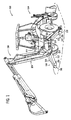
- a backhoe 100 has a chassis 102 on which an engine 104 is mounted.
- a backhoe attachment 106 extends backward from the rear of the chassis 102 to which it is pivotally coupled.
- a left stabilizer 108 and a right stabilizer 110 are pivotally coupled to the chassis 102 of the backhoe 100.
- Each stabilizer has an elongate member 112 with an upper end 114 that is pivotally coupled to the chassis 102 and a lower end 116 that terminates at and is coupled to a stabilizer pad 118.
- the stabilizer pads have flattened bottoms that are disposed to sit flat on the ground when lowered.
- the stabilizer pads 118 are pivotally coupled to ends 116 of stabilizers 108 and 110.
- Hydraulic cylinder 120 is coupled at its upper end to chassis 102 and at its lower end to elongate member 112 of the left stabilizer 108.
- hydraulic cylinder 122 is coupled at its upper end to chassis 102 and at its lower end to elongate member 112 of the right stabilizer 110.
- each hydraulic cylinder 120, 122 When each hydraulic cylinder 120, 122 is extended, it pivots the stabilizer to which it is coupled downward and into engagement with the ground. When each hydraulic cylinder 120, 122 is retracted, it pivots the stabilizer to which it is coupled upward, away from the ground and to a stowed position for travel.
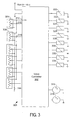
- hydraulic circuit 200 for controlling the stabilizers includes a pump 202 that is coupled to and driven by engine 104 to produce hydraulic fluid under pressure for the backhoe arm and stabilizer cylinders.
- Circuit 200 also includes a hydraulic fluid return tank 203 to which hydraulic fluid exhausted from the cylinders is returned. Pressure in the hydraulic lines coupled to the pump depends on the load, but can be as high as 3000 psig (20684 kPa or 207 bar).
- Circuit 200 also includes two valve blocks, a pilot control valve block 204 that includes the electrically-actuated pilot valves for raising and lowering the stabilizers, and a directional control valve block 206 including the main hydraulic valves for raising and lowering the stabilizers, and for operating the backhoe arm, including the boom swing cylinder 208, the boom cylinder 210, the dipper cylinder 212, the extendahoe cylinder 214, and the bucket cylinder 216.
- a pilot control valve block 204 that includes the electrically-actuated pilot valves for raising and lowering the stabilizers
- a directional control valve block 206 including the main hydraulic valves for raising and lowering the stabilizers, and for operating the backhoe arm, including the boom swing cylinder 208, the boom cylinder 210, the dipper cylinder 212, the extendahoe cylinder 214, and the bucket cylinder 216.
- Pilot control valve block 204 includes an auxiliary forward pilot valve 218, and auxiliary reverse pilot valve 220, a right stabilizer up pilot valve 222, a right stabilizer down pilot valve 224, a left stabilizer up pilot valve 226, a left stabilizer down pilot valve 228, an extendahoe retract pilot valve 230 and an extendahoe extend pilot valve 232.
- Directional control valve block 206 includes an auxiliary hydraulic valve 234, a right stabilizer valve 236, a left stabilizer valve 238, an extendahoe valve 240, a bucket valve 242, a dipper valve 244, a boom valve 246, and a boom swing valve 248.
- Circuit 200 also includes two joysticks, a left joystick 250 and a right joystick 252 that are fluidly coupled to and operate the boom swing valve 248, the boom valve 246, the dipper valve 244 and the bucket valve 242.
- Left joystick 250 includes hydraulic pilot valves that operate bucket valve 242 and dipper valve 244, which in turn are coupled to and drive bucket cylinder 216 and dipper cylinder 212, respectively.
- Right joystick 252 includes hydraulic pilot valves that operate boom valve 246 and boom swing valve 248, which in turn are coupled to and operate boom cylinder 210 and boom swing cylinder 208, respectively.
- These joysticks are configured to operate boom swing valve 248, boom valve 246, dipper valve 244, and bucket valve 242 that are located in the directional control valve block 206.
- All of the pilot valves in the pilot control valve block 204 are electrically actuated spool valves.
- Each pilot valve in block 204 has a single valve coil or solenoid to shift the valve from its illustrated deenergized neutral position.
- Each of the pilot valves when in its neutral position conducts fluid from its associated directional control hydraulic valve to which it is coupled back to tank 203.
- each pilot valve When energized, each pilot valve conducts hydraulic fluid from pump 202 through the pilot valve to each directional control valve to which it is coupled.
- All of the pilot valves in the pilot control valve block 204 are operated by a proportional electrical signal and generate an output pressure proportional to the electrical signal applied to them.
- the valves do have some hysteresis, which will be discussed below.
- the valves are preferably Thomas Magnete Proportional Pressure-Reduction valves, Thomas Magnete Part Number 52402. They have three ports and are pressure compensated. In general, these valves begin to "crack" or open with a current of 200 milliamperes at 12 volts and reach a maximum pressure with a current of 1.6 amperes at 12 volts.
- the pulse width modulated driver circuit that drives them has a frequency of between 100 and 120 Hertz.
- the output pressure generated by the pilot valves is applied to either the left or the right end of the spool of the associated directional control hydraulic valve of block 206.
- the force applied to the end of the valve spools of the directional control valves of block 206 is proportional to the hydraulic pressure applied. It is opposed by a spring acting on the opposing end of the valve spool. The distance the valve spool in block 206 moves is proportional to the hydraulic pressure applied as well, since the spring opposing force is a function of distance deflected. As a result, the spool position, and hence flow rate of fluid through each of the pilot-controlled hydraulic valves in block 206 is generally proportional to the electrical pulse width modulated ("PWM”) signal applied to the pilot valve.
- PWM pulse width modulated
- right stabilizer up pilot valve 222 When right stabilizer up pilot valve 222 is energized by its electrical coil, its spool shifts to the left, connecting hydraulic pump 202 to the left end of the spool of right stabilizer valve 236. This shifts the spool of right stabilizer valve 236 to the right from the position indicated. This movement connects pump 202 to the retract port of cylinder 122 causing right stabilizer cylinder 122 to retract. When right stabilizer cylinder 122 retracts, it lifts right stabilizer 110 upward away from the ground. Fluid from the extend port of right stabilizer cylinder 122 is automatically conducted back to tank 203.
- right stabilizer down pilot valve 224 When right stabilizer down pilot valve 224 is energized by its electrical coil, its spool shifts to the left, connecting hydraulic pump 202 to the right end of the spool of right stabilizer valve 236. This shifts the spool of right stabilizer valve 236 to the left from the position indicated. This movement connects pump 202 to the extend port of cylinder 122 causing right stabilizer cylinder 122 to extend. When right stabilizer cylinder 122 extends, it lowers right stabilizer 110 downward toward the ground. Fluid from the retract port of right stabilizer cylinder 122 is automatically conducted back to tank 203.
- left stabilizer up pilot valve 226 When left stabilizer up pilot valve 226 is energized by its electrical coil, its spool shifts to the left, connecting hydraulic pump 202 to the left end of the spool of left stabilizer valve 238. This shifts the spool of left stabilizer valve 238 to the right from the position indicated. This movement connects pump 202 to the retract port of cylinder 120 causing left stabilizer cylinder 120 to retract. When left stabilizer cylinder 120 retracts, it lifts left stabilizer 108 upward away from the ground. Fluid from the extend port of left stabilizer cylinder 120 is automatically conducted back to tank 203.
- left stabilizer down pilot valve 228 When left stabilizer down pilot valve 228 is energized by its electrical coil, its spool shifts to the left, connecting hydraulic pump 202 to the right end of the spool of left stabilizer valve 238. This shifts the spool of left stabilizer valve 238 to the left from the position indicated. This movement connects pump 202 to the extend port of cylinder 120 causing left stabilizer cylinder 120 to extend. When left stabilizer cylinder 120 extends, it lowers left stabilizer 108 downward toward the ground. Fluid from the retract port of left stabilizer cylinder 120 is automatically conducted back to tank 203.
- FIGURE 3 illustrates the electronic control circuit 300 for the backhoe of FIGURES 1 and 2.
- the core of the circuit is an electronic valve controller 302 including a digital programmable microprocessor, that is configured to receive operator commands from several operator input devices and generate responsive electrical signals that are applied to solenoids 320, 322, 324, 326, 328, 330, 332, and 334 of pilot valves 218, 220, 222, 224, 226, 228, 230, and 232 respectively.
- the electrical solenoids of these pilot valves are electrically coupled to and driven by valve controller 302 under program control.
- Control circuit 300 of FIGURE 3 includes two joysticks 304, 306 that are manually operated by the operator of the vehicle to move the stabilizers up and down.
- Left stabilizer joystick 304 and right stabilizer joystick 306 are electrically coupled to valve controller 302 to provide it with a varying voltage signal indicating the amount the joysticks are deflected away from a neutral central position.
- the joysticks are preferably Elobau joysticks (Elobau part number J3A6AS0A01) with a voltage output of between 0.5 volts and 4.5 volts from one end of joystick travel to the other.
- joysticks are preferably Hall Effect devices, they are shown symbolically in FIGURE 3 as variable resistors with a center tap 310 that provides the 0.5 to 4.5 volt signal to valve controller 302.
- Each joystick 304, 306 is electrically coupled on one side to five volt source 312 provided by valve controller 302 and at the other side to ground 314.
- the joysticks When the joysticks are manipulated by the operator, they move from one limit to another limit, generating a voltage signal at the center tap 310 that varies from 0.5 volts to 4.5 volts depending upon the position of the joystick. It is this 0.5 to 4.5 volt signal that indicates to valve controller 302 the position of the joystick.
- the voltage output in the center or neutral position of each joystick is 2.5 volts.
- the neutral position is the position located at the middle of the full range of joystick travel as illustrated in FIGURE 3.
- Valve controller 302 preferably includes a digital microcontroller with RAM and ROM, ideally flash ROM.
- the valve controller is preferably reprogrammable with a special tool to make manufacturing and rework easier.
- the digital microcontroller is preferably an 8-bit microcontroller with on-board flash memory, and analog-to-digital converter (for digitizing the signals generated by the joysticks) and PWM timers (for generating the PWM pilot valve solenoid signals from a calculated duty cycle).
- a preferred microcontroller for valve controller 302 is a PIC 16F873.
- Pressure switch 316 is coupled to the hydraulic line extending from right stabilizer valve 236 to the rod end (the retract port) of right stabilizer cylinder 122.
- Pressure switch 318 is coupled to the hydraulic line extending from left stabilizer valve 238 to the rod end (the retract port) of left stabilizer cylinder 120.
- the pressure switches are in fluid communication with these hydraulic lines to sense the rod end pressure when the stabilizers are raised. When the stabilizer cylinders are raised, they eventually reach their uppermost positions. During the period they are rising their rod end pressure is low.
- the system pressure is throttled by the stabilizer valves to insure the stabilizers rise at a relatively slow rate. As a result, the cylinder pressure is that pressure sufficient to support and slowly raise the stabilizers, on the order of a few hundred pounds per square inch.
- pressure switches 316, 318 change state. They are set to change state well above working (i.e. stabilizer lifting) pressure and well below static (i.e. system), or in the preferred arrangement illustrated here, 2750 psig (18960 kPa or 190 bar). In its auto-up modes of operation, it is the pressure switch changing state that informs the electronic controller of the system that the stabilizers have been completely raised.
- Controller 302 of control circuit 300 is coupled to and drives the pilot valve electrical solenoids of each of the pilot valves in FIGURE 2.
- These solenoids include solenoid 320 of auxiliary forward pilot valve 218, solenoid 322 of auxiliary reverse pilot valve 220, solenoid 324 of right stabilizer up pilot valve 222, solenoid 326 of right stabilizer down pilot valve 224, solenoid 328 of left stabilizer up pilot valve 226, solenoid 330 of left stabilizer down pilot valve 228, solenoid 332 of extendahoe retract pilot valve 230, and solenoid 334 of extendahoe extend pilot valve 232.
- Each of these pilot valve solenoids are operated by PWM signals generated by eight PWM driver circuits in controller 302. The solenoids and their connections to the PWM driver circuits of controller 302 are shown in FIGURE 3.
- Controller 302 is programmed to respond to the manipulation of stabilizer joysticks 304 and 306 differently in several different modes of operation.
- the top level modes of operation are called (1) the unpowered mode, (2) the neutral interlock mode, (3) the operating mode, and (4) the shutdown mode. These modes of operation are illustrated in the controller state diagram of FIGURE 4.
- the system is in the unpowered mode 400 whenever the vehicle's ignition switch is turned off or controller 302 is otherwise unpowered. Motion cannot occur when controller 302 is unpowered.
- controller 302 On power up (i.e. whenever controller 302 is initially powered up), controller 302 is programmed to leave the unpowered mode 400 and enter its neutral interlock mode of operation 402. In this mode, controller 302 does not respond to joystick commands by moving the stabilizers. Instead, it ignores any deflection of the joysticks away from their neutral position and polls a transmission neutral switch (not shown) and the stabilizer joysticks until both the transmission is placed in neutral and the joysticks are returned to their neutral positions.
- a transmission neutral switch not shown
- controller 302 is programmed to leave the neutral interlock mode 402, and automatically enter its operating mode 404.
- Controller 302 may transition from its operating mode 404 to a shutdown mode 406 under certain conditions. Controller 302 is programmed to periodically and repeatedly check the operation of the stabilizers by performing a suite of programmed diagnostic tests. Whenever any of these diagnostic tests are failed (i.e. there is a fault), controller 302 enters the shutdown mode of operation. In the shutdown mode of operation, controller 302 ceases to respond to the joysticks as it does in the operating mode (described below) and waits for the error condition or fault to be cleared.
- Controller 302 periodically executes its programmed diagnostic tests in the shutdown mode 406 until either (1) the vehicle is powered down, or (2) the fault is cleared. If the fault is cleared, controller 302 is programmed to enter its neutral interlock mode 402. If the vehicle is powered down, controller 302 again enters the unpowered mode 400.
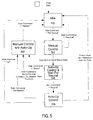
- FIGURE 5 is a state diagram indicating the different sub-modes of the operating mode 404.
- operating mode 404 there are five sub-modes, including an idle mode 500, a manual mode 502, an auto-up control and wait for neutral (“ACWFN”) mode 504, an auto-up control mode 506, and a manual control without auto-up (“MCWAU”) mode 508.
- ACWFN auto-up control and wait for neutral
- MCWAU manual control without auto-up
- Controller 302 enters the idle mode 500 immediately upon entering the operating mode 404 (of which the idle mode 500 is a sub-mode). Controller 302 is programmed to stay in the idle mode until a system fault occurs (at which time it enters shutdown mode 406), or the operator moves either one or both of the joysticks 304, 306 away from their neutral center position. Controller 302 enters the idle mode only when the stabilizer joysticks 304, 306 are in neutral. Whenever controller 302 is in the idle mode, it turns off the stabilizer pilot valves by transmitting a PWM valve signal with a duration of 0% to the stabilizer pilot valve solenoids which de-energizes them. The stabilizer cylinders cease moving.
- the second operating sub-mode is manual control mode 502. Controller 302 enters the manual control mode from idle mode 500 whenever the operator moves either stabilizer joystick 304, 306 away from its neutral position.
- controller 302 responds to movement of stabilizer joysticks 304, 306 in a programmed fashion to move the stabilizers up and down, depending upon the direction and amount joysticks 304, 306 are moved, which we will now describe.
- controller 302 enters the manual mode 502.
- the operator commands the joysticks in either the upward or in the downward direction.
- the joysticks are preferably mounted with the left joystick on the operator's left hand side, and the right joystick on the operator's right hand side.
- Controller 302 is programmed to interpret this movement as a "raise” or “up” command and begins to raise the stabilizer.
- the voltage generated by the joystick is lowered from the neutral voltage of 2.5 volts downward toward 0.5 volts.
- Controller 302 is programmed to interpret this movement as a "lower” or “down” command and lowers the stabilizer accordingly.
- Controller 302 receives the voltage signal from the joystick and converts it into a duty cycle percentage, which it then applies to its internal PWM driver circuit for the pilot valve. Controller 302 includes two lookup tables of duty cycle versus joystick position which it uses to determine the appropriate PWM duty cycle. These lookup tables are graphically illustrated in FIGURE 6.
- the "lower” or “down” lookup table used when the joystick is deflected to its “down” position to lower the stabilizer is represented as curve 600.
- the "raise” or “up” lookup table is represented as curve 602.
- the neutral position is indicated by item 604.
- the x-axis indicates the voltage signal generated by the joystick.
- the y-axis indicates the duty cycle (in percent) that controller 302 commands in response to receiving the joystick signal on the x-axis.
- controller 302 When the operator moves the joystick to the left (in FIGURE 6) he is moving it in the "down” direction, causing controller 302 to use the lookup table of curve 600 to drive the stabilizer down pilot valve solenoid with the duty cycle percentage indicated on the y-axis.
- controller 302 When the operator moves the joystick to the right (in FIGURE 6) he is moving it in the "up” direction, causing controller 302 to use the lookup table of curve 602 to drive the stabilizer up pilot valve solenoid with the duty cycle percentage indicated on the y-axis.
- the curves do not overlap, hence only one pilot valve solenoid, either the up solenoid or the down solenoid, is driven at any time.
- neutral zone of positions 604 i.e. generating voltages of between about 2.3 and 2.7 volts
- controller 302 is programmed to drive neither the up nor the down pilot valve solenoids and the stabilizer is stationary.
- the down and up lookup tables 600, 602 are not identical, as shown in FIGURE 6. Both curves start with a PWM duty cycle of about 35%, which is calculated to generate a current in the up and down solenoids sufficient to just crack the solenoid valves open. Both curves also have the same maximum PWM duty cycle of about 72%. At this duty cycle the stabilizers travel at their maximum speed, both up and down.
- the joystick has a higher resolution when moving the stabilizer down. It can be moved over a greater distance when it goes from a just-cracked condition to a full flow condition. This increased resolution gives the operator finer control of the movement of the stabilizer when it is being lowered than when it is being raised.
- the joystick has a lower resolution when raising the stabilizer, as shown by the steeper slope of the up curve 602.
- the joystick is moved over a shorter distance to go from its just-cracked condition (i.e. the stabilizer barely moves) to a full flow condition (i.e. the stabilizer moves at its fastest speed) in the up direction as compared to movement in the down direction.
- controller 302 does not change the PWM duty cycle proportional to the changing joystick position. Instead, it holds the PWM duty cycle constant at its maximum rate (i.e. about 70%). The operator senses that he has reached an upper limit of movement and that further movement of the joystick will not cause the stabilizer to rise faster, which is true.
- controller 302 exits manual control mode 502. First, when the operator returns the joystick to the neutral or center position, and second, when the operator signals that he wishes to enter the auto-up control and wait for neutral (ACWFN) mode 504. Controller 302 is configured to continuously and repeatedly sense the position of the joystick and recalculate the PWM signal when in manual control mode 502. Controller 302 is also configured to sense how long the joystick is held in a stabilizer-raising position above a predetermined joystick position (i.e. at or above a predetermined joystick voltage output).
- Controller 302 enters ACWFN mode 504 whenever the operator holds the joystick in a stabilizer-raising position that generates a voltage of 4.0 volts or more for a predetermined period of time.
- the preferred predetermined period of time is at least 0.1 seconds. Holding the joystick in the predetermined position for the predetermined period of time constitutes the auto-up command. Once controller 302 senses that the joystick has been held in this position for this minimum time period, it automatically enters the ACWFN mode 504.
- controller 302 no longer calculates the up pilot valve solenoid duty cycle based on joystick position. Instead, it continues to apply the maximum duty cycle (about 70%) to the up pilot valve solenoid. As a result, the operator need not hold the joystick in an "up” position to keep raising the stabilizer. He can release the joystick, let it return to its neutral position, and the stabilizer will continue to rise at its maximum rate.
- controller 302 is programmed to leave ACWFN sub-mode 504. The first way is by not releasing the joystick to the neutral position. Once the operator has entered ACWFN mode 504, controller 302 waits for the joystick to be returned to neutral (hence the name). Controller 302 monitors the joystick position (i.e. the joystick voltage) for a predetermined period of time, preferably within 1 to 4 seconds, more preferably, between 1.25 and 3 seconds, and even more preferably about 2 seconds. If the joystick does not return to neutral (e.g. by the operator releasing the spring-loaded joystick 304, 306) during this period of time controller 302 then enters manual control without auto-up (MCWAU) mode 508.
- MCWAU manual control without auto-up
- a "stabilizer down" joystick position is any of the joystick positions representing a command to lower the stabilizer. In this embodiment, that means the joystick positions that generate a voltage of 2.3 volts or less (see FIGURE 6).
- Controller 302 is programmed to leave the ACWFN mode 504 and enter MCWAU mode 508.
- controller 302 leaves ACWFN mode 504 and enters Auto-Up Control mode 506.
- controller 302 continues to raise the stabilizer at its maximum duty cycle (70%, in this example).
- controller 302 monitors the position of the joystick to insure the operator is not commanding the stabilizer to move to any other position.
- controller 302 is programmed to automatically exit auto-up control mode 506 and enter MCWAU mode 508.
- Controller 302 is configured to automatically leave the auto-up control mode 506 without operator intervention when two other conditions occur: (1) when the stabilizer is raised completely and (2) when the stabilizer has been in auto-up mode for a predetermined number of seconds, whichever comes first. It has been calculated for the preferred embodiment shown here that the stabilizer will be raised completely within ten seconds of starting the auto-up process if the system is working properly. Hence controller 302 monitors the time in the auto-up mode. When the time in auto-up control mode is eventually greater than the predetermined number of seconds in auto-up, controller 302 exits the auto-up control mode and enters the idle mode. While ten seconds is preferred, alternative embodiments may use a time interval of between 3 seconds and 20 seconds, more preferably between 4 seconds and 15 seconds, and even more preferably between 6 seconds and 12 seconds.
- the final way of exiting the auto-up control mode 506 is by monitoring the stabilizer cylinder and exiting mode 506 when the stabilizer is completely raised.
- controller 302 determines that the stabilizer has been completely raised when the pressure switch 316, 318 coupled to controller 302 switches "on".
- the pressure switch is in fluid communication with the retract line of the stabilizer cylinder. As long as the cylinder is retracting, the pressure in the cylinder stays below the switch pressure. When the cylinder is completely retracted, abuts its stops and the piston abruptly stops moving in the cylinder, there is a sudden pressure spike sensed by the switch that turns the pressure switch on.
- Controller 302 is programmed to monitor the state of the switch and to exit the auto-up control mode when the switch turns on -- i.e. when the stabilizer is completely raised.
- controller 302 is programmed to enter idle mode 500 and await the operator's next command.
- MCWAU mode 508 can be considered an "abort" mode.
- the system typically enters into this mode when the operator keeps moving the joystick after he has already commanded the auto-up mode to start. If he truly commanded the auto-up mode to start, he would immediately release the joystick and let the system perform its auto-up function. Since he has not done so, his continued movement may indicate he wishes to exit the auto-up mode and again take over manual control of the stabilizer with the joystick. It is with this thought in mind that the MCWAU mode was created.
- controller 302 is configured to respond just as it does in manual control mode 502 with one difference: the operator cannot directly re-enter the auto-up mode. Before he can reenter the auto-up modes he must first exit MCWAU mode 508 by releasing the joystick to its neutral position. Once he has done this, controller 302 leaves MCWAU mode 508 and returns to idle mode 500.
- Controller 302 includes a flow rate damping or ramping feature that prevents abrupt and perhaps unintended motion of the stabilizers by the operator in modes 502 and 508.
- controller 302 does not automatically and instantaneously change the duty cycle of the commanded pilot valve solenoid according to the up and down curves 602, 600 of the lookup table chart of FIGURE 6. If the operator accidentally bumps the joystick, for example, and controller 302 did not have some sort of damping, the vehicle might suddenly lurch to one side or the other. To prevent this from occurring, controller 302 is configured to change the duty cycle of the affected valve at a predetermined maximum rate of change. This damping functions generally as a low pass filter between the joystick and the pilot valve. Holding the joystick at a position indicated on the chart of FIGURE 6 will indeed cause the duty cycle to change to the duty cycle corresponding to that duty cycle on curves 600, 602; it just will not reach that commanded duty cycle instantaneously.
- This reduced response is also called a "ramp rate" and is expressed in terms of the maximum change in joystick voltage per unit time. For example, for the joystick having the voltage/duty cycle characteristics in FIGURE 6, there are four preferred ramp rates that damp the system's response to sudden changes in joystick commands.
- the maximum commanded increase in the rate of rise (i.e. transitioning from rising slow to rising fast) will be the rate that would increase the joystick signal from 2.65 volts to 4.0 volts in one second.
- this 2.65 to 4.0 volts per second maximum ramp rate is the same as one second to go from 35% to 72% duty cycle, or from 0% flow to a maximum flow, or from the stabilizer stationary to the stabilizer's maximum upward raising speed.
- Controller 302 is therefore programmed to distinguish between what might be an inadvertent bump or twitch of the joystick and the rapid back-and-forth movement or oscillation that operators perform when shaking mud. Controller 302 is programmed to stop damping the calculated PWM signal applied to the up and down pilot valves whenever the operator makes a sufficient number of wide swings of the joystick. Operators shake the stabilizer up and down by moving the joystick generally about the same central joystick position. The operator moves the joystick to an "up” position, then rapidly to a “down” position, back to an “up”, then to down”to “up”, to "down”, “up”, “down”, “up”, “down”, etc. This is significantly different than one or perhaps two inadvertent bumps of the joystick. Controller 302 takes advantage of this difference in movement in determining that the operator indeed is trying to shake the stabilizer.
- controller 302 reads each joystick command in succession, it examines them in accordance with the following pseudocoded instructions:
- controller 302 determines whether to damp the PWM signal (i.e. apply a first ramp rate) or not to damp it (i.e. apply a second higher ramp rate) and permit the operator to shake the stabilizer.
- damp_command refers to the command received from the stabilizer joystick 304 or 306.
- upper_command_limit refers to a predetermined upper value of the joystick signal (about 2.8 volts in the illustrated embodiment).
- shake_direction refers to a flag indicating the current direction of the operator's shaking (movement) of the joystick.
- lower_command_limit refers to a predetermined lower value of the joystick signal (about 2.2 volts in the illustrated embodiment).
- last_shake_direction refers to a flag indicating the direction of the last operator shaking of the joystick.
- shake timer refers to a variable that is incremented in step 8.
- maximum_shake_reversal_time refers to a predetermined value to which the shake_timer value is compared in step 10.
- controller 302 determines whether the joystick command is greater than a certain minimum “up” joystick signal, preferably around 2.8 volts. If it is, controller 302 sets the shake direction to "up”. In step 2, controller 302 checks to see if the joystick command is below a certain maximum “down” joystick signal, preferably around 2.2 volts. If so, controller 302 sets the shake direction equal to "down”. In step 3, controller 302 checks to see if the shake direction has changed from “up” to "down” or from “down” to “up”. This only happens when one joystick command is above 2.8 volts and the next joystick command is below 2.2 volts, or vice versa.
- controller 302 Since controller 302 reads the joystick commands frequently, this would indicate that the joystick was flicked back and forth. In this example, that it was first pulled down below 2.2 volts and then rapidly moved up above 2.8 volts (or vice versa) in quick succession.
- controller 302 determines there has been such a rapid movement, controller 302 then counts this as an official shake by incrementing the shake counter in step 4, and sets the last shake direction equal to the current shake direction in step 5 so its doesn't double count the shake the next time through this loop. Controller 302 also resets the shake timer to zero in step 6.
- controller 302 increments the shake timer. This occurs every time the loop is executed since it is not inside the "if" structure of steps 3-7.
- the shake timer which is reset whenever an up-down or down-up shake occurs, will be incremented or increased each time controller 302 executes this portion of its programming. It will keep incrementing the shake timer until it detects an operator shake of the joystick, at which time the shake timer is reset to zero (step 6). Thus, the larger the value of the shake timer variable, the longer the system has gone without an operator shake of the joystick.
- controller 302 compares the shake timer value with a predetermined value called max shake reversal time. This time is preferably around 600 milliseconds. If the shake timer exceeds this time, the controller 302 sets the shake count equal to zero. In this step, controller 302 checks to see if too much time has passed since the last good shake the operator has given to the joystick. If he hasn't shaken it in a while, shake timer will gradually increment until it equals max shake reversal time, and the shake counter will be rest to zero. Controller 302 will begin again counting up from zero all the times the operator shakes the joystick vigorously back and forth.
- max shake reversal time a predetermined value called max shake reversal time.
- controller 302 compares shake count with max shake reverse count, a constant value, to see if shake count is greater.
- shake count is incremented each time controller 302 determines a vigorous shake has occurred. If shake count is greater than the constant max shake reverse count, then controller 302 disables valve damping.
- Max shake reverse count is preferably 2.
- controller 302 determines and count each vigorous up-and-down shake of the joystick by the operator. Once he has made a sufficient number of joystick shakes in a predetermined short period of time, controller 302 will respond by turning off the damping that would otherwise smooth out such rapid joystick movements.
- a vigorous swing is one that moves the joystick back and forth at least from 2.8 to 2.2 volts or vice versa, passing through the neutral zone in each shake. This is a total shake distance of 0.6 volts, or about a ninth of the total zero to five volt range of the joystick.
- a sufficient number of shakes is two and the total time in which these shakes must occur is 600 milliseconds, or a speed of one shake every 300 milliseconds.
- the maximum total time may be preferably no more than 100 milliseconds per shake. Even more preferably it may be no more than 300 milliseconds per shake. Yet more preferably it may be no more than 800 milliseconds per shake.
- the shake distance of 0.6 volts (0.3 volts above joystick neutral and 0.3 volts below joystick neutral) is equivalent to a 3 degree movement of the joystick in the up direction and 3 degree movement of the joystick in the down direction, where “degrees” refers to the angle of the joystick shaft.
- the free end of the joystick moves about 0.1 to 0.5 inches.
- Controller 302 will substantially damp them out by applying the ramp rate. Once controller 302 determines (by the algorithm above) that the operator is trying to shake the stabilizer, it turns off the damping and the stabilizer will rapidly shake up and down as fast as the operator whips the joystick back and forth. When the operator slows down or stops moving the joystick back and forth from above 2.8 volts to below 2.2 volts (in this embodiment) controller 302 eventually resets the shake timer and the shake counter and enables the damping again, as provided in step 10.
- the stabilizer shake mode starts automatically in response to the operator vigorously shaking the joystick back and forth from an "up” position to a “down” position, and continues until he stops vigorously shaking the joystick. It automatically reverts back to its typical damped mode of operation.
- a single controller is illustrated herein as controlling the operation of the stabilizers, there may be more than one controller. While the controller is preferably based on a digital microprocessor or microcontroller, the controller may nonetheless be embodied in discrete logic digital and analog components. While the circuit illustrated includes two electrically driven pilot hydraulic valves coupled to a single valve that drives each stabilizer up and down, all the functions could be provided in a single valve. The pilot valves could be deleted and the signals generated by the controller applied directly to a single valve coupled to the cylinder. Rather than a single valve coupled to the cylinder, two valves, one for retract and one for the extend function could be provided instead. Further, a pilot valve could be coupled to either of the two valves coupled to the ports to drive each one individually, providing four valves for moving each stabilizer up and down.
- the joysticks could be replaced with knobs, dials or levers, and the Hall Effect device could be replaced with a shaft encoder or other digital device; or a potentiometer, variable resistor or other analog output device.
- the operator input devices i.e. the stabilizer joysticks
- the operator input devices could have their own controller with which they communicate, which could in turn transmit their joystick position signals to a second controller or controllers configured to actually control the stabilizers as described herein.
- This controller-to-controller communication can be provided by a serial communications bus using wires or optical conduits to transmit joystick position signals. It might be analog, but would more preferably be a digital communications scheme, such as packetized communication over a CAN bus wherein the packets are digital representations of the joysticks' positions.
Landscapes
- Engineering & Computer Science (AREA)
- Mining & Mineral Resources (AREA)
- Civil Engineering (AREA)
- General Engineering & Computer Science (AREA)
- Structural Engineering (AREA)
- Operation Control Of Excavators (AREA)
- Mechanical Control Devices (AREA)
- Vehicle Body Suspensions (AREA)
- Automobile Manufacture Line, Endless Track Vehicle, Trailer (AREA)
Claims (24)
- System zum automatischen Anheben eines Stützfußes oder Stabilisators (108, 110) eines Arbeitsfahrzeuges (100), wobei das System Folgendes umfasst:- eine Eingabevorrichtung (304, 306), die so konfiguriert ist, dass sie Signale erzeugt, die eine Anzahl von Stabilisator-Bewegungsgeschwindigkeiten anzeigen;- eine elektronische Steuereinrichtung (302), die so konfiguriert ist, dass sie die Signale von der Eingabevorrichtung (304, 306) empfängt und entsprechende Ventilsignale erzeugt; und- zumindest ein Hydraulikventil (218, 220, 234, 236), das mit der Steuereinrichtung (302) gekoppelt ist, um den Stabilisator (108, 110) in Abhängigkeit von den Ventilsignalen zu bewegen; unddadurch gekennzeichnet, dass die Steuereinrichtung (302):- eine erste Betriebsart, in der sie so konfiguriert ist, dass sie Signale an das zumindest eine Hydraulikventil (218, 220, 234, 236) zum Anheben und Absenken des Stabilisators (108, 110) proportional zu der Position der Eingabevorrichtung liefert, und- eine zweite Betriebsart aufweist, in der sie automatisch den Stabilisator (108, 110) auf eine vorgegebene obere Position bewegt.
- System nach Anspruch 1, dadurch gekennzeichnet, dass die Steuereinrichtung (302) so konfiguriert ist, dass sie von der ersten Betriebsart auf die zweite Betriebsart auf der Grundlage zumindest von einer Betätigung der Eingabevorrichtung (304, 306) durch den Fahrer wechselt.
- System nach Anspruch 1 oder 2, dadurch gekennzeichnet, dass die Steuereinrichtung (302) so konfiguriert ist, dass sie von der ersten Betriebsart auf die zweite Betriebsart auf der Grundlage einer Zeitperiode wechselt, über die sich die Eingabevorrichtung (304, 306) in einer von mehreren Positionen in einem vorgegebenen durchgehenden Bereich von Positionen befindet, wobei jede der mehreren Positionen ein unterschiedliches Signal von der Eingabevorrichtung (304, 306) erzeugt.
- System nach einem der vorhergehenden Ansprüche, dadurch gekennzeichnet, dass die Steuereinrichtung (302) so konfiguriert ist, dass sie die zweite Betriebsart verlässt, wenn der Stabilisator (108, 110) die vorgegebene obere Position erreicht.
- System nach einem der vorhergehenden Ansprüche, dadurch gekennzeichnet, dass die Steuereinrichtung (302) die vorgegebene obere Position durch Messen einer Hydraulikdruck-Spitze feststellt.
- System nach Anspruch 5, dadurch gekennzeichnet, dass die Steuereinrichtung (302) so konfiguriert ist, dass sie einen auf die Hydraulikdruck-Spitze ansprechenden Sensor (316, 318) überwacht.
- System nach einem der vorhergehenden Ansprüche, dadurch gekennzeichnet, dass die Steuereinrichtung (302) so konfiguriert ist, dass sie die zweite Betriebsart zumindest nach einer vorgegebenen Zeit durch Schließen des zumindest einen Ventils (218, 220, 234, 236) verlässt.
- System nach einem der vorhergehenden Ansprüche, dadurch gekennzeichnet, dass die Steuereinrichtung (302) so konfiguriert ist, dass sie die zweite Betriebsart zumindest dann verlässt, wenn der Fahrer die Eingabevorrichtung (304, 306) nicht loslässt.
- System nach einem der vorhergehenden Ansprüche, dadurch gekennzeichnet, dass das System weiterhin Folgendes umfasst:- eine zweite Eingabevorrichtung (304, 306), die zur Erzeugung zweiter Signale konfiguriert ist, die eine Anzahl von Stabilisator-Bewegungsgeschwindigkeiten für einen zweiten Stabilisator (108, 110) anzeigen, wobei die Steuereinrichtung (302) so konfiguriert ist, dass sie die zweiten Signale von der zweiten Eingabevorrichtung (304, 306) empfängt und entsprechende zweite Ventilsignale erzeugt; und- zumindest ein zweites Hydraulikventil (218, 220, 234, 236), das mit der Steuereinrichtung (302) gekoppelt ist, um den zweiten Stabilisator (108, 110) in Abhängigkeit von den zweiten Ventilsignalen zu bewegen; wobei die Steuereinrichtung (302) weiterhin so konfiguriert ist, dass sie den Stabilisator und den zweiten Stabilisator unabhängig voneinander sowohl in den ersten als auch zweiten Betriebsarten steuert.
- System nach einem der vorhergehenden Ansprüche, dadurch gekennzeichnet, dass die Steuereinrichtung (302) so konfiguriert ist, dass sie die Stabilisator-Bewegung in der ersten Betriebsart dämpft, und wobei die Steuereinrichtung (302) weiterhin so konfiguriert ist, dass sie in eine dritte weniger gedämpfte Steuer-Betriebsart eintritt.
- System nach Anspruch 10, dadurch gekennzeichnet, dass die Steuereinrichtung (302) so konfiguriert ist, dass sie in die dritte Betriebsart eintritt, wenn ein Fahrer die Eingabevorrichtung (304, 306) hin- und herbewegt.
- System nach Anspruch 11, dadurch gekennzeichnet, dass die Steuereinrichtung (302) so konfiguriert ist, dass sie in die dritte Betriebsart auf der Grundlage von zumindest der Feststellung einer vorgegebenen Anzahl von Hin- und Herbewegungen der Eingabevorrichtung (304, 306) eintritt.
- System nach einem der vorhergehenden Ansprüche, dadurch gekennzeichnet, dass in der ersten Betriebsart die Steuereinrichtung (302) so konfiguriert ist, dass sie ein Signal an das zumindest eine Hydraulikventil (218, 220, 234, 236) zum Anheben und Absenken des Stabilisators (108, 110) proportional zu der Position der Eingabevorrichtung mit zumindest einer ersten Rampen-Rate liefert, und dass in der zweiten Betriebsart die Steuereinrichtung (302) die Stabilisatoren (108, 110) proportional zu der Position der Eingabevorrichtung mit zumindest einer zweiten Rampen-Rate anhebt und absenkt, die von der ersten Rampen-Rate verschieden ist.
- System nach Anspruch 13, dadurch gekennzeichnet, dass die Steuereinrichtung (302) so konfiguriert ist, dass sie automatisch von der ersten Rampen-Rate auf die zweite Rampen-Rate auf der Grundlage von zumindest einer ersten Bewegung der Fahrer-Eingabevorrichtung (304, 306) umschaltet.
- System nach Anspruch 14, dadurch gekennzeichnet, dass die Steuereinrichtung (302) so konfiguriert ist, dass sie automatisch von der zweiten Rampen-Rate auf die erste Rampen-Rate auf der Grundlage von zumindest einer zweiten Bewegung der Fahrer-Eingabevorrichtung (304, 306) umschaltet, die eine andere Größe als die Größe der ersten Bewegung hat.
- System nach Anspruch 15, dadurch gekennzeichnet, dass die erste Bewegung (a) die Bewegung der Fahrer-Eingabevorrichtung (304, 306) über eine erste Schwellenwert-Position hinaus und (b) die Bewegung der Fahrer-Eingabevorrichtung (304, 306) unter eine zweite Schwellenwert-Position einschließt.
- System nach Anspruch 16, dadurch gekennzeichnet, dass die Fahrer-Eingabevorrichtung (304, 306) eine Mittelstellung aufweist, dass eine der ersten und zweiten Schwellenwert-Positionen auf einer Seite der Mittelstellung liegt, und dass die andere der ersten und zweiten Stellenwert-Positionen auf der anderen Seite der Mittelstellung liegt.
- System nach einem der vorhergehenden Ansprüche, dadurch gekennzeichnet, dass die Fahrer-Eingabevorrichtung (304, 306) ein Steuerknüppel ist, der zur Erzeugung von Steuerknüppel-Signalen konfiguriert ist, die allgemein proportional zu den Positionen des Steuerknüppels sind.
- System nach den Ansprüchen 13 bis 18, dadurch gekennzeichnet, dass die Steuereinrichtung (302) so konfiguriert ist, dass sie von der ersten auf die zweite Rampen-Rate wechselt, wenn der Fahrer die Fahrer-Eingabevorrichtung (304, 306) zurück und vorwärts bewegt.
- System nach Anspruch 19, dadurch gekennzeichnet, dass die Steuereinrichtung (302) so konfiguriert ist, dass sie von der ersten auf die zweite Rampen-Betriebsart wechselt, wenn der Fahrer die Fahrer-Eingabevorrichtung (304, 306) zumindest einmal innerhalb eines vorgegebenen Zeitintervalls zurück und vorwärts bewegt.
- Verfahren zum Schütteln eines Stabilisators (108, 110), der durch einen Steuerknüppel (304, 306) gesteuert wird, und
gekennzeichnet dadurch, dass das Verfahren die folgenden Schritte einschließt:- schnelles und Hin- und Herbewegen des Steuerknüppels (304, 306);- elektronisches Überwachen der schnellen Steuerknüppel-Hin- und Herbewegung; und- Verringern der Stabilisator-Dämpfungsrate in Abhängigkeit von der überwachten Hin- und Herbewegung. - Verfahren nach Anspruch 21, dadurch gekennzeichnet, dass der Schritt der elektronischen Überwachung einen Schritt der Feststellung der Anzahl von Hin- und Herbewegungen des Steuerknüppels einschließt.
- Verfahren nach Anspruch 21 und 22, dadurch gekennzeichnet, dass der Schritt der elektronischen Überwachung einen Schritt der Feststellung der abgelaufenen Zeit der Hin- und Herbewegungen einschließt.
- Verfahren nach den Ansprüchen 21 bis 23, dadurch gekennzeichnet, dass der Schritt der elektronischen Überwachung einen Schritt der Feststellung einer Größe der Hin- und Herbewegungen einschließt.
Applications Claiming Priority (2)
| Application Number | Priority Date | Filing Date | Title |
|---|---|---|---|
| US689483 | 2003-10-20 | ||
| US10/689,483 US7114747B2 (en) | 2003-10-20 | 2003-10-20 | Work vehicle stabilizer |
Publications (2)
| Publication Number | Publication Date |
|---|---|
| EP1526221A1 EP1526221A1 (de) | 2005-04-27 |
| EP1526221B1 true EP1526221B1 (de) | 2007-09-19 |
Family
ID=34394521
Family Applications (1)
| Application Number | Title | Priority Date | Filing Date |
|---|---|---|---|
| EP04104930A Expired - Lifetime EP1526221B1 (de) | 2003-10-20 | 2004-10-08 | Stützfussanordnung für Arbeitsfahrzeug und Verfahren zur Steuerung dieser Anordnung. |
Country Status (4)
| Country | Link |
|---|---|
| US (2) | US7114747B2 (de) |
| EP (1) | EP1526221B1 (de) |
| AT (1) | ATE373749T1 (de) |
| DE (1) | DE602004009016T2 (de) |
Cited By (2)
| Publication number | Priority date | Publication date | Assignee | Title |
|---|---|---|---|---|
| WO2009099529A3 (en) * | 2008-01-31 | 2009-10-15 | Caterpillar Inc. | Tool control system |
| WO2009111363A3 (en) * | 2008-02-29 | 2009-11-12 | Caterpillar Inc. | Semi-autonomous excavation control system |
Families Citing this family (25)
| Publication number | Priority date | Publication date | Assignee | Title |
|---|---|---|---|---|
| US20060229787A1 (en) * | 2005-04-08 | 2006-10-12 | Kurup Prasaad B | Electro-hydraulic control process and work machine using same |
| US7430954B2 (en) * | 2005-09-26 | 2008-10-07 | Kubota Corporation | Work machine |
| US7745484B2 (en) * | 2005-11-21 | 2010-06-29 | Amgen Inc. | Beta-secretase modulators and methods of use |
| FR2894330B1 (fr) | 2005-12-05 | 2008-03-07 | Giat Ind Sa | Dispositif d'autodefense contre les mines |
| US7784581B1 (en) * | 2006-09-14 | 2010-08-31 | Deere & Company | Machine control interlocks for an electrohydraulically controlled vehicle |
| US7726048B2 (en) | 2006-11-30 | 2010-06-01 | Caterpillar Inc. | Automated machine repositioning in an excavating operation |
| US8078297B2 (en) * | 2006-12-01 | 2011-12-13 | Trimble Navigation Limited | Interface for retrofitting a manually controlled machine for automatic control |
| US7729835B2 (en) * | 2007-08-21 | 2010-06-01 | Jcb Compact Products Limited | Method of controlling a working machine |
| US7866149B2 (en) * | 2007-09-05 | 2011-01-11 | Caterpillar Inc | System and method for rapidly shaking an implement of a machine |
| US9037355B2 (en) * | 2007-11-05 | 2015-05-19 | Deere & Company | Control assembly for auxiliary hydraulics |
| JP5391040B2 (ja) | 2009-11-26 | 2014-01-15 | キャタピラー エス エー アール エル | 作業機械の旋回油圧制御装置 |
| US9096095B2 (en) * | 2010-02-17 | 2015-08-04 | Justoy Pty Ltd | Handling device and method |
| JP5298069B2 (ja) * | 2010-05-20 | 2013-09-25 | 株式会社小松製作所 | 電動アクチュエータの制御装置 |
| US9440357B2 (en) * | 2011-05-02 | 2016-09-13 | John Hu | System for stabilization control of mobile robotics |
| US9846675B2 (en) * | 2012-06-11 | 2017-12-19 | Robert Bosch Gmbh | Dual path control for vehicle joystick controller |
| GB2522050B (en) | 2014-01-13 | 2016-12-14 | Jc Bamford Excavators Ltd | A method of operating a material handling machine |
| US20170121930A1 (en) * | 2014-06-02 | 2017-05-04 | Komatsu Ltd. | Construction machine control system, construction machine, and method of controlling construction machine |
| US10442411B2 (en) * | 2017-03-29 | 2019-10-15 | Lippert Components, Inc. | Manually-operable hydraulic stabilizing system |
| US11052878B2 (en) * | 2017-03-29 | 2021-07-06 | Lippert Components, Inc. | Manually-operable hydraulic stabilizing system |
| US11885221B2 (en) | 2018-02-27 | 2024-01-30 | Joy Global Surface Mining Inc | Shovel stabilizer appendage |
| US10801182B2 (en) | 2018-10-19 | 2020-10-13 | Cnh Industrial America Llc | System and method for controlling work vehicle operation based on multi-mode identification of operator inputs |
| US11732442B2 (en) | 2019-11-21 | 2023-08-22 | Cnh Industrial America Llc | System and method for controlling the operation of a work vehicle to provide improved responsiveness when commanding implement movement |
| GB2593759B (en) | 2020-04-02 | 2023-04-26 | Caterpillar Inc | Method and control unit for generating a control command to at least one actuator of an electro-hydraulic machine |
| GB202019672D0 (en) * | 2020-12-14 | 2021-01-27 | Caterpillar Sarl | Hydraulic control system and method for a bucket shake operation in a work machine with a hydraulic pump and unloader valve |
| US12320100B2 (en) * | 2022-10-05 | 2025-06-03 | Deere & Company | Automatic mode for object detection range setting |
Family Cites Families (21)
| Publication number | Priority date | Publication date | Assignee | Title |
|---|---|---|---|---|
| US3912288A (en) * | 1974-08-21 | 1975-10-14 | Us Army | Vehicle level control |
| US4473239A (en) * | 1982-06-03 | 1984-09-25 | Smart Robert L | Stabilizer pad assembly |
| US4679489A (en) * | 1985-11-04 | 1987-07-14 | Becor Western Inc. | Automatic leveling system for blast hole drills and the like |
| US4746133A (en) * | 1987-02-19 | 1988-05-24 | Hwh Corporation | Automatic leveling system |
| US4865295A (en) * | 1987-06-17 | 1989-09-12 | Holloway Lowell E | Holloway's self-deploying stabilizing jack |
| US5188379A (en) * | 1990-10-19 | 1993-02-23 | Applied Mechanis, Inc. | Automatic leveling system for recreational vehicles |
| US5176391A (en) * | 1991-10-24 | 1993-01-05 | Versa Technologies, Inc. | Vehicle leveling system |
| US5628521A (en) * | 1993-07-26 | 1997-05-13 | Versa Technologies, Inc. | Manually operated vehicle leveling system |
| US5537818A (en) * | 1994-10-31 | 1996-07-23 | Caterpillar Inc. | Method for controlling an implement of a work machine |
| US5642653A (en) * | 1995-10-23 | 1997-07-01 | Caterpillar Inc. | Method and apparatus for providing detents on an electronic control handle |
| US6058342A (en) * | 1996-07-25 | 2000-05-02 | Case Corporation | Precision control of implement position/motion |
| US5685377A (en) * | 1996-09-05 | 1997-11-11 | Caterpillar Inc. | Auto-return function for a bulldozer ripper |
| JPH11286391A (ja) * | 1998-03-31 | 1999-10-19 | Aichi Corp | 作業車のジャッキ支持力検出装置 |
| US5996342A (en) * | 1998-06-23 | 1999-12-07 | Case Corporation | Hydrostatic drive train controller |
| EP1019313B1 (de) * | 1998-08-04 | 2003-07-09 | Ingersoll-Rand Company | System zum nivellieren und abstützen von dem rahmen eines gabelhubwagens |
| US6481749B2 (en) * | 1999-05-18 | 2002-11-19 | Caterpillar Inc | Auto-up switch for simultaneously retracting a pair of stabilizer legs on a backhoe loader machine |
| US6584385B1 (en) * | 1999-10-01 | 2003-06-24 | Innovative Design Solutions, Inc. | Vehicle leveling assembly |
| US6877773B1 (en) * | 2000-06-05 | 2005-04-12 | Caterpillar Inc | Pilot hydraulic control for a pair of stabilizer legs on a backhoe loader machine |
| US6561076B2 (en) * | 2001-04-30 | 2003-05-13 | Case Corporation | Differential configuration of remote hydraulic valve flow rates for extend and retract modes of operation |
| US20030001373A1 (en) * | 2001-06-28 | 2003-01-02 | Slater Ken G. | Center pivot stabilizer apparatus |
| JP2004019806A (ja) * | 2002-06-17 | 2004-01-22 | Hitachi Constr Mach Co Ltd | 作業車両の油圧回路 |
-
2003
- 2003-10-20 US US10/689,483 patent/US7114747B2/en not_active Expired - Lifetime
-
2004
- 2004-10-08 AT AT04104930T patent/ATE373749T1/de not_active IP Right Cessation
- 2004-10-08 EP EP04104930A patent/EP1526221B1/de not_active Expired - Lifetime
- 2004-10-08 DE DE602004009016T patent/DE602004009016T2/de not_active Expired - Lifetime
-
2006
- 2006-06-21 US US11/471,886 patent/US7434838B2/en active Active
Cited By (3)
| Publication number | Priority date | Publication date | Assignee | Title |
|---|---|---|---|---|
| WO2009099529A3 (en) * | 2008-01-31 | 2009-10-15 | Caterpillar Inc. | Tool control system |
| WO2009111363A3 (en) * | 2008-02-29 | 2009-11-12 | Caterpillar Inc. | Semi-autonomous excavation control system |
| EP2255040A4 (de) * | 2008-02-29 | 2013-05-08 | Caterpillar Inc | Halbautonomes aushubsteuerungssystem |
Also Published As
| Publication number | Publication date |
|---|---|
| ATE373749T1 (de) | 2007-10-15 |
| US7434838B2 (en) | 2008-10-14 |
| US20060237958A1 (en) | 2006-10-26 |
| DE602004009016D1 (de) | 2007-10-31 |
| US20050082809A1 (en) | 2005-04-21 |
| EP1526221A1 (de) | 2005-04-27 |
| US7114747B2 (en) | 2006-10-03 |
| DE602004009016T2 (de) | 2007-12-27 |
Similar Documents
| Publication | Publication Date | Title |
|---|---|---|
| EP1526221B1 (de) | Stützfussanordnung für Arbeitsfahrzeug und Verfahren zur Steuerung dieser Anordnung. | |
| US6564548B2 (en) | Speed control apparatus of working vehicle and speed control method thereof | |
| US7797934B2 (en) | Anti-stall system utilizing implement pilot relief | |
| EP1361312A1 (de) | Einrichtung und Methode zum Vibrieren eines Anbauteiles an einer Arbeitsmaschine | |
| CN100378276C (zh) | 机械控制装置及方法 | |
| CN213270501U (zh) | 自动倾斜控制系统 | |
| JP4223893B2 (ja) | 作業車両の作業機用油圧ポンプの制御方法と制御装置 | |
| KR100806269B1 (ko) | 유압식 굴삭차량 | |
| EP1263673B1 (de) | Arbeitsmaschine | |
| US7104054B1 (en) | Hydraulic cylinder cushioning | |
| JP3805200B2 (ja) | 作業車 | |
| JPH0771057A (ja) | バックホウ | |
| JP4490654B2 (ja) | 作業機のアクセル制御装置 | |
| JPH06185093A (ja) | ホイールローダのフロント制御装置 | |
| JP2723116B2 (ja) | ハンドリング装置 | |
| KR200159839Y1 (ko) | 휠로더의 붐 위치를 다단계로 조절하기 위한 제어장치 | |
| JP4007593B2 (ja) | 作業車両の作業機用油圧ポンプの制御装置 | |
| JP4841832B2 (ja) | クレーンの作動速度制御装置 | |
| JP2682926B2 (ja) | バックホーの油圧制御装置 | |
| JP3688205B2 (ja) | 作業車 | |
| JP2635852B2 (ja) | バックホウ | |
| JP2010029124A (ja) | 対地作業機牽引作業車両 | |
| JPH05195559A (ja) | バックホーの油圧制御装置 | |
| JP2624405B2 (ja) | 作業車の作業装置姿勢制御構造 | |
| JPH053365U (ja) | ローダの制御装置 |
Legal Events
| Date | Code | Title | Description |
|---|---|---|---|
| PUAI | Public reference made under article 153(3) epc to a published international application that has entered the european phase |
Free format text: ORIGINAL CODE: 0009012 |
|
| AK | Designated contracting states |
Kind code of ref document: A1 Designated state(s): AT BE BG CH CY CZ DE DK EE ES FI FR GB GR HU IE IT LI LU MC NL PL PT RO SE SI SK TR |
|
| AX | Request for extension of the european patent |
Extension state: AL HR LT LV MK |
|
| 17P | Request for examination filed |
Effective date: 20051013 |
|
| AKX | Designation fees paid |
Designated state(s): AT BE BG CH CY CZ DE DK EE ES FI FR GB GR HU IE IT LI LU MC NL PL PT RO SE SI SK TR |
|
| GRAP | Despatch of communication of intention to grant a patent |
Free format text: ORIGINAL CODE: EPIDOSNIGR1 |
|
| RTI1 | Title (correction) |
Free format text: WORK VEHICLE STABILIZER AND METHOD OF CONTROLLING SAID STABILIZER. |
|
| GRAS | Grant fee paid |
Free format text: ORIGINAL CODE: EPIDOSNIGR3 |
|
| GRAA | (expected) grant |
Free format text: ORIGINAL CODE: 0009210 |
|
| AK | Designated contracting states |
Kind code of ref document: B1 Designated state(s): AT BE BG CH CY CZ DE DK EE ES FI FR GB GR HU IE IT LI LU MC NL PL PT RO SE SI SK TR |
|
| REG | Reference to a national code |
Ref country code: GB Ref legal event code: FG4D |
|
| REG | Reference to a national code |
Ref country code: CH Ref legal event code: EP |
|
| REF | Corresponds to: |
Ref document number: 602004009016 Country of ref document: DE Date of ref document: 20071031 Kind code of ref document: P |
|
| REG | Reference to a national code |
Ref country code: IE Ref legal event code: FG4D |
|
| PG25 | Lapsed in a contracting state [announced via postgrant information from national office to epo] |
Ref country code: FI Free format text: LAPSE BECAUSE OF FAILURE TO SUBMIT A TRANSLATION OF THE DESCRIPTION OR TO PAY THE FEE WITHIN THE PRESCRIBED TIME-LIMIT Effective date: 20070919 |
|
| ET | Fr: translation filed | ||
| PG25 | Lapsed in a contracting state [announced via postgrant information from national office to epo] |
Ref country code: PL Free format text: LAPSE BECAUSE OF FAILURE TO SUBMIT A TRANSLATION OF THE DESCRIPTION OR TO PAY THE FEE WITHIN THE PRESCRIBED TIME-LIMIT Effective date: 20070919 Ref country code: CH Free format text: LAPSE BECAUSE OF FAILURE TO SUBMIT A TRANSLATION OF THE DESCRIPTION OR TO PAY THE FEE WITHIN THE PRESCRIBED TIME-LIMIT Effective date: 20070919 Ref country code: LI Free format text: LAPSE BECAUSE OF FAILURE TO SUBMIT A TRANSLATION OF THE DESCRIPTION OR TO PAY THE FEE WITHIN THE PRESCRIBED TIME-LIMIT Effective date: 20070919 Ref country code: AT Free format text: LAPSE BECAUSE OF FAILURE TO SUBMIT A TRANSLATION OF THE DESCRIPTION OR TO PAY THE FEE WITHIN THE PRESCRIBED TIME-LIMIT Effective date: 20070919 |
|
| NLV1 | Nl: lapsed or annulled due to failure to fulfill the requirements of art. 29p and 29m of the patents act | ||
| PG25 | Lapsed in a contracting state [announced via postgrant information from national office to epo] |
Ref country code: BE Free format text: LAPSE BECAUSE OF FAILURE TO SUBMIT A TRANSLATION OF THE DESCRIPTION OR TO PAY THE FEE WITHIN THE PRESCRIBED TIME-LIMIT Effective date: 20070919 |
|
| REG | Reference to a national code |
Ref country code: CH Ref legal event code: PL |
|
| PG25 | Lapsed in a contracting state [announced via postgrant information from national office to epo] |
Ref country code: GR Free format text: LAPSE BECAUSE OF FAILURE TO SUBMIT A TRANSLATION OF THE DESCRIPTION OR TO PAY THE FEE WITHIN THE PRESCRIBED TIME-LIMIT Effective date: 20071220 Ref country code: ES Free format text: LAPSE BECAUSE OF FAILURE TO SUBMIT A TRANSLATION OF THE DESCRIPTION OR TO PAY THE FEE WITHIN THE PRESCRIBED TIME-LIMIT Effective date: 20071230 Ref country code: NL Free format text: LAPSE BECAUSE OF FAILURE TO SUBMIT A TRANSLATION OF THE DESCRIPTION OR TO PAY THE FEE WITHIN THE PRESCRIBED TIME-LIMIT Effective date: 20070919 |
|
| PG25 | Lapsed in a contracting state [announced via postgrant information from national office to epo] |
Ref country code: CZ Free format text: LAPSE BECAUSE OF FAILURE TO SUBMIT A TRANSLATION OF THE DESCRIPTION OR TO PAY THE FEE WITHIN THE PRESCRIBED TIME-LIMIT Effective date: 20070919 Ref country code: PT Free format text: LAPSE BECAUSE OF FAILURE TO SUBMIT A TRANSLATION OF THE DESCRIPTION OR TO PAY THE FEE WITHIN THE PRESCRIBED TIME-LIMIT Effective date: 20080219 Ref country code: MC Free format text: LAPSE BECAUSE OF NON-PAYMENT OF DUE FEES Effective date: 20071031 Ref country code: SK Free format text: LAPSE BECAUSE OF FAILURE TO SUBMIT A TRANSLATION OF THE DESCRIPTION OR TO PAY THE FEE WITHIN THE PRESCRIBED TIME-LIMIT Effective date: 20070919 |
|
| PG25 | Lapsed in a contracting state [announced via postgrant information from national office to epo] |
Ref country code: RO Free format text: LAPSE BECAUSE OF FAILURE TO SUBMIT A TRANSLATION OF THE DESCRIPTION OR TO PAY THE FEE WITHIN THE PRESCRIBED TIME-LIMIT Effective date: 20070919 Ref country code: SE Free format text: LAPSE BECAUSE OF FAILURE TO SUBMIT A TRANSLATION OF THE DESCRIPTION OR TO PAY THE FEE WITHIN THE PRESCRIBED TIME-LIMIT Effective date: 20071219 |
|
| PLBE | No opposition filed within time limit |
Free format text: ORIGINAL CODE: 0009261 |
|
| STAA | Information on the status of an ep patent application or granted ep patent |
Free format text: STATUS: NO OPPOSITION FILED WITHIN TIME LIMIT |
|
| PG25 | Lapsed in a contracting state [announced via postgrant information from national office to epo] |
Ref country code: DK Free format text: LAPSE BECAUSE OF FAILURE TO SUBMIT A TRANSLATION OF THE DESCRIPTION OR TO PAY THE FEE WITHIN THE PRESCRIBED TIME-LIMIT Effective date: 20070919 |
|
| 26N | No opposition filed |
Effective date: 20080620 |
|
| PG25 | Lapsed in a contracting state [announced via postgrant information from national office to epo] |
Ref country code: IE Free format text: LAPSE BECAUSE OF NON-PAYMENT OF DUE FEES Effective date: 20071008 |
|
| PG25 | Lapsed in a contracting state [announced via postgrant information from national office to epo] |
Ref country code: EE Free format text: LAPSE BECAUSE OF FAILURE TO SUBMIT A TRANSLATION OF THE DESCRIPTION OR TO PAY THE FEE WITHIN THE PRESCRIBED TIME-LIMIT Effective date: 20070919 |
|
| PG25 | Lapsed in a contracting state [announced via postgrant information from national office to epo] |
Ref country code: SI Free format text: LAPSE BECAUSE OF FAILURE TO SUBMIT A TRANSLATION OF THE DESCRIPTION OR TO PAY THE FEE WITHIN THE PRESCRIBED TIME-LIMIT Effective date: 20070919 |
|
| PG25 | Lapsed in a contracting state [announced via postgrant information from national office to epo] |
Ref country code: CY Free format text: LAPSE BECAUSE OF FAILURE TO SUBMIT A TRANSLATION OF THE DESCRIPTION OR TO PAY THE FEE WITHIN THE PRESCRIBED TIME-LIMIT Effective date: 20070919 |
|
| PG25 | Lapsed in a contracting state [announced via postgrant information from national office to epo] |
Ref country code: BG Free format text: LAPSE BECAUSE OF FAILURE TO SUBMIT A TRANSLATION OF THE DESCRIPTION OR TO PAY THE FEE WITHIN THE PRESCRIBED TIME-LIMIT Effective date: 20071219 Ref country code: LU Free format text: LAPSE BECAUSE OF NON-PAYMENT OF DUE FEES Effective date: 20071008 |
|
| PG25 | Lapsed in a contracting state [announced via postgrant information from national office to epo] |
Ref country code: TR Free format text: LAPSE BECAUSE OF FAILURE TO SUBMIT A TRANSLATION OF THE DESCRIPTION OR TO PAY THE FEE WITHIN THE PRESCRIBED TIME-LIMIT Effective date: 20070919 Ref country code: HU Free format text: LAPSE BECAUSE OF FAILURE TO SUBMIT A TRANSLATION OF THE DESCRIPTION OR TO PAY THE FEE WITHIN THE PRESCRIBED TIME-LIMIT Effective date: 20080320 |
|
| REG | Reference to a national code |
Ref country code: DE Ref legal event code: R082 Ref document number: 602004009016 Country of ref document: DE Representative=s name: PATENTANWAELTE WALLACH, KOCH & PARTNER, DE |
|
| REG | Reference to a national code |
Ref country code: DE Ref legal event code: R082 Ref document number: 602004009016 Country of ref document: DE Representative=s name: PATENTANWAELTE WALLACH, KOCH & PARTNER, DE Effective date: 20140623 Ref country code: DE Ref legal event code: R081 Ref document number: 602004009016 Country of ref document: DE Owner name: CNH INDUSTRIAL ITALIA S.P.A., IT Free format text: FORMER OWNER: CNH ITALIA S.P.A., MODENA, IT Effective date: 20140623 Ref country code: DE Ref legal event code: R082 Ref document number: 602004009016 Country of ref document: DE Representative=s name: PATENTANWAELTE WALLACH, KOCH, DR. HAIBACH, FEL, DE Effective date: 20140623 |
|
| REG | Reference to a national code |
Ref country code: FR Ref legal event code: CD Owner name: CNH INDUSTRIAL ITALIA S.P.A. Effective date: 20150313 |
|
| REG | Reference to a national code |
Ref country code: FR Ref legal event code: PLFP Year of fee payment: 12 |
|
| REG | Reference to a national code |
Ref country code: FR Ref legal event code: PLFP Year of fee payment: 13 |
|
| REG | Reference to a national code |
Ref country code: FR Ref legal event code: PLFP Year of fee payment: 14 |
|
| REG | Reference to a national code |
Ref country code: FR Ref legal event code: PLFP Year of fee payment: 15 |
|
| PGFP | Annual fee paid to national office [announced via postgrant information from national office to epo] |
Ref country code: DE Payment date: 20191029 Year of fee payment: 16 |
|
| PGFP | Annual fee paid to national office [announced via postgrant information from national office to epo] |
Ref country code: FR Payment date: 20191026 Year of fee payment: 16 |
|
| PGFP | Annual fee paid to national office [announced via postgrant information from national office to epo] |
Ref country code: GB Payment date: 20191025 Year of fee payment: 16 |
|
| REG | Reference to a national code |
Ref country code: DE Ref legal event code: R082 Ref document number: 602004009016 Country of ref document: DE Representative=s name: MEISSNER BOLTE PATENTANWAELTE RECHTSANWAELTE P, DE |
|
| REG | Reference to a national code |
Ref country code: DE Ref legal event code: R119 Ref document number: 602004009016 Country of ref document: DE |
|
| GBPC | Gb: european patent ceased through non-payment of renewal fee |
Effective date: 20201008 |
|
| PG25 | Lapsed in a contracting state [announced via postgrant information from national office to epo] |
Ref country code: FR Free format text: LAPSE BECAUSE OF NON-PAYMENT OF DUE FEES Effective date: 20201031 Ref country code: DE Free format text: LAPSE BECAUSE OF NON-PAYMENT OF DUE FEES Effective date: 20210501 |
|
| PG25 | Lapsed in a contracting state [announced via postgrant information from national office to epo] |
Ref country code: GB Free format text: LAPSE BECAUSE OF NON-PAYMENT OF DUE FEES Effective date: 20201008 |
|
| PGFP | Annual fee paid to national office [announced via postgrant information from national office to epo] |
Ref country code: IT Payment date: 20211012 Year of fee payment: 18 |
|
| PG25 | Lapsed in a contracting state [announced via postgrant information from national office to epo] |
Ref country code: IT Free format text: LAPSE BECAUSE OF NON-PAYMENT OF DUE FEES Effective date: 20221008 |