EP1526237A1 - Vorrichtung zum Verriegeln und zum Betätigen von Klappen, Türen oder dgl. - Google Patents
Vorrichtung zum Verriegeln und zum Betätigen von Klappen, Türen oder dgl. Download PDFInfo
- Publication number
- EP1526237A1 EP1526237A1 EP04020366A EP04020366A EP1526237A1 EP 1526237 A1 EP1526237 A1 EP 1526237A1 EP 04020366 A EP04020366 A EP 04020366A EP 04020366 A EP04020366 A EP 04020366A EP 1526237 A1 EP1526237 A1 EP 1526237A1
- Authority
- EP
- European Patent Office
- Prior art keywords
- handle
- flap
- spring member
- housing
- counter
- Prior art date
- Legal status (The legal status is an assumption and is not a legal conclusion. Google has not performed a legal analysis and makes no representation as to the accuracy of the status listed.)
- Granted
Links
Images



Classifications
-
- E—FIXED CONSTRUCTIONS
- E05—LOCKS; KEYS; WINDOW OR DOOR FITTINGS; SAFES
- E05B—LOCKS; ACCESSORIES THEREFOR; HANDCUFFS
- E05B77/00—Vehicle locks characterised by special functions or purposes
-
- E—FIXED CONSTRUCTIONS
- E05—LOCKS; KEYS; WINDOW OR DOOR FITTINGS; SAFES
- E05C—BOLTS OR FASTENING DEVICES FOR WINGS, SPECIALLY FOR DOORS OR WINDOWS
- E05C3/00—Fastening devices with bolts moving pivotally or rotatively
- E05C3/12—Fastening devices with bolts moving pivotally or rotatively with latching action
- E05C3/16—Fastening devices with bolts moving pivotally or rotatively with latching action with operating handle or equivalent member moving otherwise than rigidly with the latch
- E05C3/22—Fastening devices with bolts moving pivotally or rotatively with latching action with operating handle or equivalent member moving otherwise than rigidly with the latch the bolt being spring controlled
- E05C3/24—Fastening devices with bolts moving pivotally or rotatively with latching action with operating handle or equivalent member moving otherwise than rigidly with the latch the bolt being spring controlled in the form of a bifurcated member
-
- E—FIXED CONSTRUCTIONS
- E05—LOCKS; KEYS; WINDOW OR DOOR FITTINGS; SAFES
- E05C—BOLTS OR FASTENING DEVICES FOR WINGS, SPECIALLY FOR DOORS OR WINDOWS
- E05C5/00—Fastening devices with bolts moving otherwise than only rectilinearly and only pivotally or rotatively
- E05C5/02—Fastening devices with bolts moving otherwise than only rectilinearly and only pivotally or rotatively both moving axially and turning about their axis to secure the wing
- E05C5/04—Fastening devices with bolts moving otherwise than only rectilinearly and only pivotally or rotatively both moving axially and turning about their axis to secure the wing performing both movements simultaneously, e.g. screwing into a keeper
Definitions
- the device in this case comprises a bolt, which a return spring is pressed into a blocking position, while an outside of the Flap arranged stationary shoulder engages behind.
- the device includes but also a handle, which has an inner end and an outer end and of a Spring force is held in a rest position in the housing. By manual pressure on the inner end becomes the handle from its rest position in an intermediate layer swung out where it can be comfortably grasped by the human hand. In this intermediate position, the bolt is still in its locked position. Then but the handle is manually from their liner in a working position on pivotable. About provided on the device control means is then the Latch transferred from its locked position into a release position, where the bolt the fixed shoulder releases. Then the flap can be opened by means of the handle become.
- Space-saving is a device that in the preamble of claim 1 specified type (DE 35 32 152 C1), because there the pivoting movement of the handle between the rest position and intermediate layer on the one hand and between the intermediate layer and working position on the other hand by two spaced pivot axes takes place and thereby in the operation of the handle two different Lever arm lengths generated.
- this known device are two physically different axle bolts provided, of which a bolt in a rotatably mounted with the handle tab is, while the other axle is accommodated in a bearing block located in the housing.
- This bracket is also used for pivotal mounting as a rotatable hook trained tie.
- the two axle bolts are interconnected by a tab connected, by means of which a different pivoting operation of the handle is possible.
- the handle rotates about a first axis, which from the axle is determined on the flap of the handle. This is done by manual pressure on Outer end of the handle. Then there is a short lever arm length. It will the inner end of the handle swings out of the housing and can then be good be taken by the hand.
- a second from the other Achsbolzen formed pivot axis is effective.
- the handle acts only as a one-armed lever with large lever length and acting as a bar pivoting hook then a stationary shoulder in the vehicle free.
- This device still requires several elements, namely two axle bolts and tabs for connecting the two Axle.
- the invention is based on the object, the known device of the To simplify the preamble of claim 1 mentioned type without the Functional safety of locking and operating the handle to endanger. This is achieved according to the invention by the measures mentioned in claim 1, the following special significance.
- the invention requires only a single axle, the storage and Leadership is assigned only one slot.
- the in the preamble of claim 1 mentioned two different pivot axes during the initial phase and the final phase of the actuation of the handle achieves the invention simply by that the axle bolt automatically into two mutually different sections of the Slot passes.
- the axle pin in an initial section of the Slot where the first pivot axis arises.
- the second pivot axis for the handle is produced.
- components are saved, whereby their production and Assembly in the device accounts. Because of the dropped components can be in the device according to the invention, the dimensions of the housing on out. This will save space in the cargo compartment under the hatch.
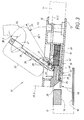
- the first device 10 according to the invention shown in FIGS. 1 to 4 is on installed free end of a flap 11, of which only a fragment dash-dotted lines is clarified.
- the flap 11 is in a the various components the device 10 receiving two-part housing 12, 13 integrated.
- the two Housing parts consist of a profiled housing upper part 12 and a Caseback 13.
- a latch 20 which in present case is designed as a slide and in the housing in the sense of Double arrow 21 is longitudinally movable.
- the inner end of the slider 22 is of a Return spring 14 in the sense of the force arrow 15 spring loaded and thereby normally pushed out of the housing 12, 13.
- the locking end 22 from the slide 20 then engages behind a stationary shoulder 16 in a dash-dotted line clarified vehicle floor 17 located massive locking piece 18. Then the slider 20 is in its clarified by an auxiliary line 20.1 Locking position shown in FIG. 1. In the vehicle floor 17 is also still a stationary Support surface 19 is provided at which the closed flap 11 with the bottom the housing bottom 13 is supported.
- the blocking position 20.1 of the slider 20 is determined by internal stops, against which the restoring force 15 acts.
- a stop is suitable
- plunger 40 which integrally with a flexible Tongue 23 is formed.
- the tongue 23 generates a valve 20 integrated in the Spring member.
- the plunger 40 is supported in Fig. 1, inter alia, with its outer edge at a shoulder 24 in the bottom portion 58 of the upper housing part 12 from.
- the plunger 40 There is another function to be described later.
- the Paragraph 24 is created here by the inner edge of an outbreak 25 in the bottom area of the upper housing part 12. Under the outbreak 25 is also a Opening 26 in the housing bottom 13th
- a handle 30 is pivotally mounted in a special way.
- the handle comprises two, as outer end 31 and inner end 32 even closer descriptive end portions and is of a spring force 35 in a through the Auxiliary line 30.0 illustrated in Fig. 1 illustrated neutral position.
- the spring force 35 is from a between the inside of the handle 30 and the upper housing part 12th produced with his two legs supporting leg spring 34.
- In the rest position 30.0 is the handle 30 with its outside substantially flush with the surface of the upper housing part 12th
- a single Axle pin 27 which received in a bearing block 44 from the upper housing part 12 is.
- the axle 27 passes through a slot 37 and is located in one on the Bottom of the handle 30 sitting rib-like protruding tabs 33. It could, at a distance from each other, two such lobes 33 at the Handle 30 may be provided, in which two ends of the same axle pin 27th protrude.
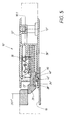
- the axle pin 27 is in a first portion 38 of the slot 37 and thus determines one with 41 in Fig. 2nd marked first pivot axis position with respect to the handle 30.
- This section 38 of the slot 37 is at the same time the one end portion of the circle segment 37, the now acts as a first bearing eye for the axle 27 and therefore "beginning section" to be called.
- the first pivot axis 41 determines a double arm of the Handle 30 with the two mutually directed away lever arms 51, 52nd Der Lever arm 51 is pivoted downward, whereby the other lever arm 52 from the Upper housing part 12 comes out. Then there is a designated grip point 36 for the hand tips 47 of the human hand 45 are conveniently accessible.
- the handle pivoted about the axis 41 30 is in a illustrated by the auxiliary line 30.1 intermediate layer 30.1. It comes on the Bottom of the handle 30 provided approach 49 in the region of a hollow profile 29 from the slider 20, whereby the slider 20 initially described in its Lock position 20.1 remains. The flap 11 is still opposite the Vehicle floor 17 locked.
- the pivot axis 42 is in the handle 30 to the aforementioned length 55 offset from the first axis 41.
- the Handle 30 now acts as a one-armed lever 50.
- the reached in Fig. 3 Pivot position 30.2 of Fig. 3 is still the following special closing technical Meaning too.
- a second embodiment 10 'of the device according to the invention As well mentioned, in Figs. 5 to 7, a second embodiment 10 'of the device according to the invention. As far as a match Assembled with the first device 10 of Figs. 1 to 4, were the same Reference numeral used. In that regard, the previous description applies. It takes just to get into the differences.
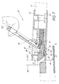
- the main difference is that a plunger 40 'instead of the slider 20' from a molded on the housing spring member 60 is located.
- This Counter spring member 60 is formed by a gap in the bottom portion 58 'of Housing upper part 12 'in Fig. 5 at the point where in the corresponding bottom portion 58th the first device 10 according to FIG. 1, the outbreak 25 was provided.
- the counter-spring member 60 is formed in the manner of a tongue and should therefore, for distinction from the slider-side tongue 23 'as a "counter-tongue" be designated.
- the tongue 23 'of the device 10' thus has a smooth Bottom, without plunger.
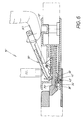
- Fig. 5 shows again, analogous to FIG. 1, the rest position 30.0 of the handle 30th on the one hand and the locking position 20.1 'of the slider 20' on the other. It supports the ram end 43 'located on the counter-tongue 60 is stationary Support surface 19 and bends not only his own counter tongue 60, but also the slide-side tongue 23 'arranged above it.
- the free Tongue end 28 ' takes in relation to the paragraph 24' from the upper housing part 12 ' a similar height position, as the tongue end 28 in Fig. 1st
- FIG. 6 corresponds to FIG Device 10 'the ratios in Fig. 2 of the previously described Device 10.
- Fig. 6 the described intermediate position 30.1 of the handle 30 before.
- the tongue 23 'and the counter tongue 60 take, in analogy to Fig. 2, the the same positions as in Fig. 5 in the device 10 'a. This changes only in Fig. 7.
Landscapes
- Engineering & Computer Science (AREA)
- Mechanical Engineering (AREA)
- Steering Devices For Bicycles And Motorcycles (AREA)
- Lock And Its Accessories (AREA)
- Pinball Game Machines (AREA)
- Coin-Freed Apparatuses For Hiring Articles (AREA)
Abstract
Description
- Fig. 1
- ein erstes Ausführungsbeispiel der erfindungsgemäßen Vorrichtung, wo die Klappe geschlossen ist, der Riegel sich in seiner Sperrstellung befindet und die unbetätigte Handhabe ihre Ruhelage einnimmt,
- Fig. 2
- die gleiche Vorrichtung bei geschlossener Klappe, wenn die Handhabe sich schon in einer Anfangsphase ihrer Betätigung befindet, während der Riegel noch in seiner Sperrstellung ist,
- Fig. 3
- die gleiche Vorrichtung, nachdem eine Endbetätigung der Handhabe erfolgte und der Riegel in seine Freigabestellung überführt worden ist und die sicher von der Hand erfasste Handhabe dabei ist, die Klappe zu öffnen,
- Fig. 4
- die gleiche Vorrichtung, nachdem die Handhabe losgelassen wurde und sich wieder in ihre Ruhelage im Gehäuse zurückbewegt hat, der Riegel aber sich noch in seiner Freigabestellung befindet und die Klappe dabei ist, geschlossen zu werden und
- Fig. 5 bis 7
- die entsprechenden Längsschnitte einer zweiten Ausführung der erfindungsgemäßen Vorrichtung, wobei diese Figuren die zu Fig. 1, 2 und 3 analogen Positionen der Bauteile einnehmen.
- 10
- erste Vorrichtung (Fig. 1 bis 4)
- 10'
- zweite Vorrichtung (Fig. 5 bis 7)
- 11
- Klappe (Fig. 1)
- 12
- Gehäuse, Gehäuseoberteil (Fig. 1)
- 12'
- Gehäuse, Gehäuseoberteil (Fig. 5 bis 7)
- 13
- Gehäuse, Gehäuseboden (Fig. 1)
- 13'
- Gehäuse, Gehäuseboden (Fig. 5 bis 7)
- 14
- Rückstellfeder (Fig. 1)
- 15
- Pfeil der Rückstellkraft von 14 auf 20 (Fig. 1)
- 15'
- Pfeil der Rückstellkraft für 20' (Fig. 7)
- 16
- Schulter für 22 (Fig. 1)
- 17
- Fahrzeugboden (Fig. 1)
- 18
- Sperrstück in 17 (Fig. 1 )
- 19
- Stützfläche in 17 (Fig. 1)
- 20
- Riegel, Schieber (Fig. 1)
- 20'
- Riegel, Schieber (Fig. 5 bis 7)
- 20.1
- Sperrstellung von 20 (Fig. 2)
- 20.1'
- Sperrstellung von 20' (Fig. 5 bis 7)
- 20.2
- Freigabestellung von 20 (Fig. 1 )
- 20.2'
- Freigabestellung von 20' (Fig. 5 bis 7)
- 21
- Pfeil der Längsbewegung von 20 (Fig. 1)
- 22
- Verriegelungsende von 20 (Fig. 1)
- 23
- Federglied, biegsame Zunge (Fig. 1 )
- 23'
- Federglied, biegsame Zunge (Fig. 5 bis 7)
- 24
- Absatz in 12 (Fig. 1)
- 24'
- Absatz in 12' (Fig. 5 bis 7)
- 25
- Ausbruch in 12 (Fig. 1 )
- 26
- Öffnung in 13 (Fig. 1)
- 26'
- Öffnung in 13' (Fig. 5 bis 7)
- 27
- Achsbolzen (Fig. 2)
- 28
- freies Zungenende von 23 (Fig. 2)
- 28'
- freies Zungenende von 23' (Fig. 7)
- 29
- Hohlprofil in 20 für 49 (Fig. 2)
- 30
- Handhabe (Fig. 1)
- 30.0
- Ruhelage von 30 (Fig. 1 bzw. Fig. 5)
- 30.1
- Zwischenlage von 30 (Fig. 2 bzw. Fig. 6)
- 30.2
- Arbeitslage von 30 (Fig. 3 bzw. Fig. 7)
- 31
- Außenende von 30 (Fig. 1)
- 32
- Innenende von 30 (Fig. 1)
- 33
- Lappen an 30 (Fig. 1)
- 34
- Schenkelfeder für 30 (Fig. 1)
- 35
- Pfeil der Federkraft von 34 auf 30 (Fig. 1)
- 36
- Griffstelle von 30 für 47 (Fig. 2, 3)
- 37
- Schlitz, Kreissegment (Fig. 2)
- 38
- erster Abschnitt, Anfangsabschnitt von 37 (Fig. 2)
- 39
- zweiter Abschnitt, Endabschnitt von 37 (Fig. 3)
- 40
- Stößel an 23 (Fig. 1)
- 40'
- Stößel an 60 (Fig. 5)
- 41
- erste Schwenkachse für 30 (Fig. 2 bzw. 6)
- 42
- zweite Schwenkachse von 30 (Fig. 3 bzw. 7)
- 43
- Stirnende von 40 (Fig. 2, 3)
- 43'
- Stirnende von 40' (Fig. 5)
- 44
- Lagerbock in 12 für 27 (Fig. 2)
- 45
- menschliche Hand (Fig. 2)
- 46
- Finger von 45 (Fig. 2)
- 47
- Handspitze von 45 (Fig. 2)
- 48
- manueller Druck auf 31 (Fig. 2)
- 49
- Ansatz an 30 (Fig. 2)
- 50
- einarmiger Hebel von 30 (Fig. 3)
- 51
- erster Arm von 30 (Fig. 2)
- 52
- zweiter Arm von 30 (Fig. 2)
- 53
- Anfangsphase der Schwenkbetätigung von 30 (Fig. 2)
- 54
- Endphase der Schwenkbetätigung von 30 (Fig. 3)
- 55
- Längsversatz zwischen 53, 54 (Fig. 3)
- 56
- Anhebebewegung von 11 (Fig. 3)
- 57
- Absenkbewegung von 11 (Fig. 4)
- 58
- Bodenbereich von 12 (Fig. 1)
- 58'
- Bodenbereich von 13' (Fig. 5)
- 59
- Steg an 20 (Fig. 2, 3)
- 60
- Gegenfederglied, Gegenzunge
- 61
- Einschubstrecke von 20' zwischen 20.1' und 20.2' (Fig. 7)
Claims (13)
- Vorrichtung (10) zum Verriegeln und zum Betätigen von Klappen (11) oder Türen, insbesondere an Fahrzeugen
mit einem in der Klappe (11) sitzenden Gehäuse (12, 13),
mit einem im Gehäuse (12, 13) beweglichen Riegel (20), der von einer Rückstellfeder (15) in eine Sperrstellung (20.1) gedrückt wird und eine außerhalb der Klappe (11) angeordnete ortsfeste Schulter (16) hintergreift,
und mit einer Handhabe (30), die ein Innenende (32) und ein Außenende (31) aufweist und von einer Federkraft (35) in eine Ruhelage (30.0) im Gehäuse (12, 13) gehalten wird,
wobei die Handhabe (30) durch manuellen Druck (48) an ihrem Außenende (31) aus ihrer Ruhelage (30.0) um eine erste Achse (Schwenkachse 41) in eine Zwischenlage (30.1) verschwenkbar (53) ist,
in der Zwischenlage (30.1) das Innenende (32) der Handhabe (30) bequem erfasst werden kann, während der Riegel (20) zunächst in seiner Sperrstellung (20.1) verbleibt,
aber dann die Handhabe (30) manuell aus ihrer Zwischenlage (30.1) um eine zweite Achse (Schwenkachse 42) in eine Arbeitslage (30.2) weiter verschwenkbar (54) ist,
bis Steuermittel den Riegel (20) aus der Sperrstellung (20.1) in eine Freigabestellung (20.2) bringen, wo die ortsfeste Schulter (16) freigegeben ist und die Klappe (11) mittels der Handhabe (30) geöffnet (56) werden kann,
wobei die beiden Schwenkachsen (41, 42) zueinander beanstandet sind und an der Handhabe (30) zwei unterschiedlich lange Hebelarme (51, 52; 50) erzeugen,
dadurch gekennzeichnet, dass zwischen dem Gehäuse (12, 13) und der Handhabe (30) nur ein Achsbolzen (27) sowie ein ihn aufnehmender Schlitz (37) angeordnet sind,
dass der Achsbolzen (27) beim anfänglichen Verschwenken (53) der Handhabe (30) aus der Ruhelage (30.0) in die Zwischenlage (30.1) sich in einem Anfangsabschnitt (38) des Schlitzes (37) befindet und dort die erste Schwenkachse (41) bestimmt,
und dass beim späteren Weiterschwenken (54) der Handhabe (30) aus der Zwischenlage (30.1) in die Arbeitslage (30.2) der Achsbolzen (27) im Schlitz (37) weiterbewegt wird, bis er in einen Endabschnitt (39) des Schlitzes (37) gelangt und dort die zweite Schwenkachse (42) für die Handhabe (30) erzeugt. - Verschluss (10) nach Anspruch 1, dadurch gekennzeichnet, dass der Achsbolzen (27) am Gehäuse (12, 13) sitzt
und dass der Schlitz (37) sich in einem Lappen (33) befindet, der mit der Handhabe (30) fest verbunden ist und bei der Schwenkbewegung (53; 54) mit verschwenkt wird. - Verschluss (10) nach Anspruch 1 oder 2, dadurch gekennzeichnet, dass der Schlitz (37) ein Kreissegment ist,
dass der Anfangsabschnitt (38) und der Endabschnitt (39) des Schlitzes (37) von den beiden Enden des Segments gebildet sind
und dass die beiden Segment-Enden (38, 39) als Lageraugen für den Achsbolzen (27) fungieren und dort die Lage der ersten und zweiten Schwenkachse (41, 42) bestimmen. - Verschluss (10) nach einem der Ansprüche 1 bis 3, dadurch gekennzeichnet, dass die Steuermittel für den Riegel (20) aus einer Schulter (49) an der Handhabe (30) und einer Gegenschulter (59) am Riegel (20) bestehen,
dass die Schulter (49) und die Gegenschulter (59) mindestens in der Ruhelage (30.0) voneinander entfernt sind,
aber spätestens beim Weiterverschwenken (54) von der Zwischenlage (30.1) in die Arbeitslage (30.2) aneinander stoßen,
und dabei den Riegel (20) aus der Sperrstellung (20.1) in die Freigabestellung (20.2) überführen (21). - Verschluss (10) nach einem der Ansprüche 1 bis 4, dadurch gekennzeichnet, dass der Riegel ein Schieber (20) ist, der im Gehäuse (12, 13) längsverschieblich (21) geführt ist.
- Verschluss (10) nach Anspruch 4 und 5, dadurch gekennzeichnet, dass der Schieber (20) einen gegen die Handhabe (30) weisenden Steg (59) und die Handhabe (30) einen dem Schieber (20) zugekehrten Ansatz (49) besitzen,
wobei die eine Flanke des Stegs (59) die Schulter und das Ende des Ansatzes (49) die Gegenschulter zur Verstellung (21) des Schiebers (20) erzeugen. - Verschluss (10; 10') nach Anspruch 5 oder 6, dadurch gekennzeichnet, dass der Schieber (20; 20') ein Federglied (23; 23') aufweist, welches in der Freigabestellung (20.1; 20.1') und bei geöffneter Klappe (11) einen Absatz (24; 24') im Gehäuse (12; 13) hintergreift,
dass ein Stößel (40; 40') zwischen der Federzunge (23; 23') und einer ortsfesten Stützfläche (19) angeordnet ist
und dass der Stößel (40; 40') bei geschlossener Klappe (11) das Federglied (23; 23') soweit zurückdrückt,
bis das Federglied (23; 23') den Absatz (24; 24') am Gehäuse (12; 13) verlässt und der Schieber (20; 20') von seiner Rückstellfeder (15) in seine Sperrstellung (20.1; 20.1') bewegt wird. - Verschluss (10) nach Anspruch 7, dadurch gekennzeichnet, dass der Stößel (40) am Federglied (23) sitzt und mit seinem Stößelende (43) gegen die Stützfläche (19) gerichtet ist,
dass der Stößel (40) bei offener Klappe (11) an der Unterseite der Klappe (11) federnd herausragt, aber bei geschlossener Klappe (11) das Federglied (23) unmittelbar zurückdrückt. - Verschluss (10') nach Anspruch 7, dadurch gekennzeichnet, dass der Stößel (40') an einem Gegenfederglied (60) sitzt und mit seinem Stößelende (43') gegen die Stützfläche (19) gerichtet ist,
dass das Gegenfederglied (60) wenigstens bereichsweise unterhalb des schieberseitigen Federglieds (23') angeordnet ist
und dass der Stößel (40') bei offener Klappe (11) an der Unterseite der Klappe (11) federnd herausragt,
aber bei geschlossener Klappe (11) das Federglied (23') mittelbar über das Gegenfederglied (60) zurückdrückt. - Verschluss nach Anspruch 7, dadurch gekennzeichnet, dass der Stößel an der ortsfesten Stützfläche sitzt und mit seinem Stößelende gegen das Federglied oder das Gegenfederglied gerichtet ist
und dass der Stößel mit einer Öffnung an der Unterseite der Klappe ausgerichtet ist,
in welche das Stößelende bei geschlossener Klappe einfährt und gegen das Federglied oder das Gegenfederglied stößt. - Verschluss (10; 10') nach einem der Ansprüche 7 bis 10, dadurch gekennzeichnet, dass das Federglied am Schieber (20; 20') aus einer biegsamen Zunge (23; 23') besteht.
- Verschluss (10') nach einem der Ansprüche 7 bis 11, dadurch gekennzeichnet, dass das Gegenfederglied am Gehäuse (13) aus einer biegsamen Gegenzunge (60) gebildet ist.
- Verschluss (10; 10') nach Anspruch 10 oder 11, dadurch gekennzeichnet, dass die Zunge (23; 23') einstückig mit dem Schieber (20; 20') und/oder die Gegenzunge (60) einstückig mit dem Gehäuse (13) ausgebildet sind.
Applications Claiming Priority (2)
| Application Number | Priority Date | Filing Date | Title |
|---|---|---|---|
| DE10349928 | 2003-10-25 | ||
| DE10349928A DE10349928B4 (de) | 2003-10-25 | 2003-10-25 | Vorrichtung zum Verriegeln und zum Betätigen von Klappen, Türen od. dgl. |
Publications (2)
| Publication Number | Publication Date |
|---|---|
| EP1526237A1 true EP1526237A1 (de) | 2005-04-27 |
| EP1526237B1 EP1526237B1 (de) | 2006-06-07 |
Family
ID=34384481
Family Applications (1)
| Application Number | Title | Priority Date | Filing Date |
|---|---|---|---|
| EP04020366A Expired - Lifetime EP1526237B1 (de) | 2003-10-25 | 2004-08-27 | Vorrichtung zum Verriegeln und zum Betätigen von Klappen, Türen oder dgl. |
Country Status (4)
| Country | Link |
|---|---|
| EP (1) | EP1526237B1 (de) |
| AT (1) | ATE329106T1 (de) |
| DE (2) | DE10349928B4 (de) |
| ES (1) | ES2262073T3 (de) |
Cited By (2)
| Publication number | Priority date | Publication date | Assignee | Title |
|---|---|---|---|---|
| DE102009007451A1 (de) * | 2009-02-04 | 2010-08-05 | Volkswagen Ag | Betätigungsgriff an einem Ladeboden für ein Fahrzeug |
| US20180339664A1 (en) * | 2015-12-22 | 2018-11-29 | Ford Global Technologies, Llc | Handle device and a trunk carpet assembly |
Families Citing this family (2)
| Publication number | Priority date | Publication date | Assignee | Title |
|---|---|---|---|---|
| DE20316663U1 (de) | 2003-10-29 | 2004-01-08 | Böllhoff GmbH | Schloss mit lösbarer Verrastung |
| CN110219528B (zh) * | 2019-07-02 | 2024-01-16 | 宁波华德汽车零部件有限公司 | 一种车用把手结构 |
Citations (4)
| Publication number | Priority date | Publication date | Assignee | Title |
|---|---|---|---|---|
| US3259411A (en) * | 1963-12-17 | 1966-07-05 | Camloc Fastener Corp | Drawhook toggle latch |
| US3782141A (en) * | 1972-10-26 | 1974-01-01 | Hansen Mfg Co A L | Flush type door latch |
| GB2180291A (en) * | 1985-09-10 | 1987-03-25 | Daimler Benz Ag | A locking device |
| DE19537672A1 (de) * | 1995-10-10 | 1997-04-17 | Huelsbeck & Fuerst | Verschluß für bewegliche Teile in Fahrzeugen |
Family Cites Families (1)
| Publication number | Priority date | Publication date | Assignee | Title |
|---|---|---|---|---|
| US5409272A (en) * | 1993-06-28 | 1995-04-25 | Southco, Inc. | Over-center latch assembly |
-
2003
- 2003-10-25 DE DE10349928A patent/DE10349928B4/de not_active Withdrawn - After Issue
-
2004
- 2004-08-27 EP EP04020366A patent/EP1526237B1/de not_active Expired - Lifetime
- 2004-08-27 DE DE502004000700T patent/DE502004000700D1/de not_active Expired - Lifetime
- 2004-08-27 AT AT04020366T patent/ATE329106T1/de not_active IP Right Cessation
- 2004-08-27 ES ES04020366T patent/ES2262073T3/es not_active Expired - Lifetime
Patent Citations (4)
| Publication number | Priority date | Publication date | Assignee | Title |
|---|---|---|---|---|
| US3259411A (en) * | 1963-12-17 | 1966-07-05 | Camloc Fastener Corp | Drawhook toggle latch |
| US3782141A (en) * | 1972-10-26 | 1974-01-01 | Hansen Mfg Co A L | Flush type door latch |
| GB2180291A (en) * | 1985-09-10 | 1987-03-25 | Daimler Benz Ag | A locking device |
| DE19537672A1 (de) * | 1995-10-10 | 1997-04-17 | Huelsbeck & Fuerst | Verschluß für bewegliche Teile in Fahrzeugen |
Cited By (4)
| Publication number | Priority date | Publication date | Assignee | Title |
|---|---|---|---|---|
| DE102009007451A1 (de) * | 2009-02-04 | 2010-08-05 | Volkswagen Ag | Betätigungsgriff an einem Ladeboden für ein Fahrzeug |
| EP2216206A3 (de) * | 2009-02-04 | 2013-01-09 | Volkswagen Aktiengesellschaft | Betätigungsgriff an einem Ladeboden für ein Fahrzeug |
| US20180339664A1 (en) * | 2015-12-22 | 2018-11-29 | Ford Global Technologies, Llc | Handle device and a trunk carpet assembly |
| US10793088B2 (en) * | 2015-12-22 | 2020-10-06 | Ford Global Technologies, Llc | Handle device and a trunk carpet assembly |
Also Published As
| Publication number | Publication date |
|---|---|
| DE10349928A1 (de) | 2005-06-16 |
| ES2262073T3 (es) | 2006-11-16 |
| DE10349928B4 (de) | 2006-08-24 |
| ATE329106T1 (de) | 2006-06-15 |
| DE502004000700D1 (de) | 2006-07-20 |
| EP1526237B1 (de) | 2006-06-07 |
Similar Documents
| Publication | Publication Date | Title |
|---|---|---|
| EP1526236A2 (de) | Vorrichtung zum Verriegeln und zum Betätigen von Klappen, Türen oder dgl. | |
| DE2444628C2 (de) | Panikverschluß | |
| DE3943715C2 (de) | Drehstangenverschluß | |
| DE3626798C2 (de) | ||
| DE19510618A1 (de) | Kraftfahrzeugsitz, der im vorgeklappten Zustand der Rückenlehne längsverschiebbar ist | |
| EP2094923B1 (de) | Verriegelungsvorrichtung für schiebetüren von luftfahrzeugen, insbesondere von hubschraubern | |
| DE2348998A1 (de) | Tuerentriegelung, insbesondere fuer notausgaenge | |
| EP1337417B1 (de) | Kraftfahrzeugsitz | |
| EP1555363B1 (de) | Betätigungsvorrichtung für Türen oder Klappen an Fahrzeugen | |
| EP2327850B1 (de) | Schloss mit Panikfunktion | |
| EP2749721B1 (de) | Treibriegelschloss | |
| EP3071770A1 (de) | Kraftfahrzeugtürverschluss | |
| EP1440930A2 (de) | Türverschluss mit Notentriegelung | |
| EP1364099B1 (de) | Vorrichtung zur betätigung eines verschlusses von türen, klappen od. dgl., insbesondere an fahrzeugen | |
| EP1526237B1 (de) | Vorrichtung zum Verriegeln und zum Betätigen von Klappen, Türen oder dgl. | |
| DE102008015655A1 (de) | Panikschloss | |
| DE3819521B4 (de) | Mechanisch betätigtes Türschloß für Kraftfahrzeuge | |
| EP3122968B1 (de) | Schaltschloss mit manipulationssicherung gegen hilfsfallenbetätigung | |
| AT398155B (de) | Skischuh | |
| DE10151870A1 (de) | Vorrichtung zur Betätigung eines Verschlusses von Türen oder Klappen, insbesondere an Fahrzeugen | |
| DE102017119252A1 (de) | Funktionskomponente einer Kraftfahrzeugschlossanordnung | |
| EP0167767A2 (de) | Verriegelungsvorrichtung mit wenigstens einem Riegel od. dgl. und mit einer Sperre für diesen Riegel | |
| EP1291477A2 (de) | Vorrichtung zur Betätigung einer Tür, einer Klappe od. dgl., insbesondere an Fahrzeugtüren | |
| WO2009109149A9 (de) | Geteilte heckklappe für ein fahrzeug sowie öffnungsverfahren | |
| WO2001016435A1 (de) | Betätigungseinrichtung für eine ablaufarmatur eines spülkastens |
Legal Events
| Date | Code | Title | Description |
|---|---|---|---|
| PUAI | Public reference made under article 153(3) epc to a published international application that has entered the european phase |
Free format text: ORIGINAL CODE: 0009012 |
|
| AK | Designated contracting states |
Kind code of ref document: A1 Designated state(s): AT BE BG CH CY CZ DE DK EE ES FI FR GB GR HU IE IT LI LU MC NL PL PT RO SE SI SK TR |
|
| AX | Request for extension of the european patent |
Extension state: AL HR LT LV MK |
|
| 17P | Request for examination filed |
Effective date: 20050419 |
|
| AKX | Designation fees paid |
Designated state(s): AT BE BG CH CY CZ DE DK EE ES FI FR GB GR HU IE IT LI LU MC NL PL PT RO SE SI SK TR |
|
| GRAP | Despatch of communication of intention to grant a patent |
Free format text: ORIGINAL CODE: EPIDOSNIGR1 |
|
| GRAS | Grant fee paid |
Free format text: ORIGINAL CODE: EPIDOSNIGR3 |
|
| GRAA | (expected) grant |
Free format text: ORIGINAL CODE: 0009210 |
|
| AK | Designated contracting states |
Kind code of ref document: B1 Designated state(s): AT BE BG CH CY CZ DE DK EE ES FI FR GB GR HU IE IT LI LU MC NL PL PT RO SE SI SK TR |
|
| PG25 | Lapsed in a contracting state [announced via postgrant information from national office to epo] |
Ref country code: PL Free format text: LAPSE BECAUSE OF FAILURE TO SUBMIT A TRANSLATION OF THE DESCRIPTION OR TO PAY THE FEE WITHIN THE PRESCRIBED TIME-LIMIT Effective date: 20060607 Ref country code: IE Free format text: LAPSE BECAUSE OF FAILURE TO SUBMIT A TRANSLATION OF THE DESCRIPTION OR TO PAY THE FEE WITHIN THE PRESCRIBED TIME-LIMIT Effective date: 20060607 Ref country code: FI Free format text: LAPSE BECAUSE OF FAILURE TO SUBMIT A TRANSLATION OF THE DESCRIPTION OR TO PAY THE FEE WITHIN THE PRESCRIBED TIME-LIMIT Effective date: 20060607 Ref country code: IT Free format text: LAPSE BECAUSE OF FAILURE TO SUBMIT A TRANSLATION OF THE DESCRIPTION OR TO PAY THE FEE WITHIN THE PRESCRIBED TIME-LIMIT;WARNING: LAPSES OF ITALIAN PATENTS WITH EFFECTIVE DATE BEFORE 2007 MAY HAVE OCCURRED AT ANY TIME BEFORE 2007. THE CORRECT EFFECTIVE DATE MAY BE DIFFERENT FROM THE ONE RECORDED. Effective date: 20060607 Ref country code: NL Free format text: LAPSE BECAUSE OF FAILURE TO SUBMIT A TRANSLATION OF THE DESCRIPTION OR TO PAY THE FEE WITHIN THE PRESCRIBED TIME-LIMIT Effective date: 20060607 Ref country code: CZ Free format text: LAPSE BECAUSE OF FAILURE TO SUBMIT A TRANSLATION OF THE DESCRIPTION OR TO PAY THE FEE WITHIN THE PRESCRIBED TIME-LIMIT Effective date: 20060607 Ref country code: SK Free format text: LAPSE BECAUSE OF FAILURE TO SUBMIT A TRANSLATION OF THE DESCRIPTION OR TO PAY THE FEE WITHIN THE PRESCRIBED TIME-LIMIT Effective date: 20060607 Ref country code: GB Free format text: LAPSE BECAUSE OF FAILURE TO SUBMIT A TRANSLATION OF THE DESCRIPTION OR TO PAY THE FEE WITHIN THE PRESCRIBED TIME-LIMIT Effective date: 20060607 Ref country code: SI Free format text: LAPSE BECAUSE OF FAILURE TO SUBMIT A TRANSLATION OF THE DESCRIPTION OR TO PAY THE FEE WITHIN THE PRESCRIBED TIME-LIMIT Effective date: 20060607 Ref country code: RO Free format text: LAPSE BECAUSE OF FAILURE TO SUBMIT A TRANSLATION OF THE DESCRIPTION OR TO PAY THE FEE WITHIN THE PRESCRIBED TIME-LIMIT Effective date: 20060607 |
|
| REG | Reference to a national code |
Ref country code: GB Ref legal event code: FG4D Free format text: NOT ENGLISH |
|
| REG | Reference to a national code |
Ref country code: CH Ref legal event code: EP |
|
| REG | Reference to a national code |
Ref country code: IE Ref legal event code: FG4D Free format text: LANGUAGE OF EP DOCUMENT: GERMAN |
|
| REF | Corresponds to: |
Ref document number: 502004000700 Country of ref document: DE Date of ref document: 20060720 Kind code of ref document: P |
|
| PG25 | Lapsed in a contracting state [announced via postgrant information from national office to epo] |
Ref country code: MC Free format text: LAPSE BECAUSE OF NON-PAYMENT OF DUE FEES Effective date: 20060831 Ref country code: BE Free format text: LAPSE BECAUSE OF NON-PAYMENT OF DUE FEES Effective date: 20060831 |
|
| PG25 | Lapsed in a contracting state [announced via postgrant information from national office to epo] |
Ref country code: DK Free format text: LAPSE BECAUSE OF FAILURE TO SUBMIT A TRANSLATION OF THE DESCRIPTION OR TO PAY THE FEE WITHIN THE PRESCRIBED TIME-LIMIT Effective date: 20060907 Ref country code: SE Free format text: LAPSE BECAUSE OF FAILURE TO SUBMIT A TRANSLATION OF THE DESCRIPTION OR TO PAY THE FEE WITHIN THE PRESCRIBED TIME-LIMIT Effective date: 20060907 |
|
| PG25 | Lapsed in a contracting state [announced via postgrant information from national office to epo] |
Ref country code: PT Free format text: LAPSE BECAUSE OF FAILURE TO SUBMIT A TRANSLATION OF THE DESCRIPTION OR TO PAY THE FEE WITHIN THE PRESCRIBED TIME-LIMIT Effective date: 20061107 |
|
| REG | Reference to a national code |
Ref country code: ES Ref legal event code: FG2A Ref document number: 2262073 Country of ref document: ES Kind code of ref document: T3 |
|
| NLV1 | Nl: lapsed or annulled due to failure to fulfill the requirements of art. 29p and 29m of the patents act | ||
| GBV | Gb: ep patent (uk) treated as always having been void in accordance with gb section 77(7)/1977 [no translation filed] |
Effective date: 20060607 |
|
| REG | Reference to a national code |
Ref country code: IE Ref legal event code: FD4D |
|
| PLBE | No opposition filed within time limit |
Free format text: ORIGINAL CODE: 0009261 |
|
| STAA | Information on the status of an ep patent application or granted ep patent |
Free format text: STATUS: NO OPPOSITION FILED WITHIN TIME LIMIT |
|
| EN | Fr: translation not filed | ||
| 26N | No opposition filed |
Effective date: 20070308 |
|
| PG25 | Lapsed in a contracting state [announced via postgrant information from national office to epo] |
Ref country code: AT Free format text: LAPSE BECAUSE OF NON-PAYMENT OF DUE FEES Effective date: 20060827 |
|
| BERE | Be: lapsed |
Owner name: HUF HULSBECK & FURST G.M.B.H. & CO. KG Effective date: 20060831 |
|
| PG25 | Lapsed in a contracting state [announced via postgrant information from national office to epo] |
Ref country code: GR Free format text: LAPSE BECAUSE OF FAILURE TO SUBMIT A TRANSLATION OF THE DESCRIPTION OR TO PAY THE FEE WITHIN THE PRESCRIBED TIME-LIMIT Effective date: 20060908 Ref country code: FR Free format text: LAPSE BECAUSE OF FAILURE TO SUBMIT A TRANSLATION OF THE DESCRIPTION OR TO PAY THE FEE WITHIN THE PRESCRIBED TIME-LIMIT Effective date: 20070309 |
|
| PG25 | Lapsed in a contracting state [announced via postgrant information from national office to epo] |
Ref country code: BG Free format text: LAPSE BECAUSE OF FAILURE TO SUBMIT A TRANSLATION OF THE DESCRIPTION OR TO PAY THE FEE WITHIN THE PRESCRIBED TIME-LIMIT Effective date: 20060907 Ref country code: EE Free format text: LAPSE BECAUSE OF FAILURE TO SUBMIT A TRANSLATION OF THE DESCRIPTION OR TO PAY THE FEE WITHIN THE PRESCRIBED TIME-LIMIT Effective date: 20060607 |
|
| PG25 | Lapsed in a contracting state [announced via postgrant information from national office to epo] |
Ref country code: LU Free format text: LAPSE BECAUSE OF NON-PAYMENT OF DUE FEES Effective date: 20060827 Ref country code: HU Free format text: LAPSE BECAUSE OF FAILURE TO SUBMIT A TRANSLATION OF THE DESCRIPTION OR TO PAY THE FEE WITHIN THE PRESCRIBED TIME-LIMIT Effective date: 20061208 Ref country code: TR Free format text: LAPSE BECAUSE OF FAILURE TO SUBMIT A TRANSLATION OF THE DESCRIPTION OR TO PAY THE FEE WITHIN THE PRESCRIBED TIME-LIMIT Effective date: 20060607 |
|
| PG25 | Lapsed in a contracting state [announced via postgrant information from national office to epo] |
Ref country code: FR Free format text: LAPSE BECAUSE OF FAILURE TO SUBMIT A TRANSLATION OF THE DESCRIPTION OR TO PAY THE FEE WITHIN THE PRESCRIBED TIME-LIMIT Effective date: 20060607 Ref country code: CY Free format text: LAPSE BECAUSE OF FAILURE TO SUBMIT A TRANSLATION OF THE DESCRIPTION OR TO PAY THE FEE WITHIN THE PRESCRIBED TIME-LIMIT Effective date: 20060607 |
|
| REG | Reference to a national code |
Ref country code: CH Ref legal event code: PL |
|
| PG25 | Lapsed in a contracting state [announced via postgrant information from national office to epo] |
Ref country code: LI Free format text: LAPSE BECAUSE OF NON-PAYMENT OF DUE FEES Effective date: 20080831 Ref country code: CH Free format text: LAPSE BECAUSE OF NON-PAYMENT OF DUE FEES Effective date: 20080831 |
|
| PGFP | Annual fee paid to national office [announced via postgrant information from national office to epo] |
Ref country code: ES Payment date: 20140812 Year of fee payment: 11 |
|
| REG | Reference to a national code |
Ref country code: DE Ref legal event code: R084 Ref document number: 502004000700 Country of ref document: DE |
|
| REG | Reference to a national code |
Ref country code: ES Ref legal event code: FD2A Effective date: 20160926 |
|
| PG25 | Lapsed in a contracting state [announced via postgrant information from national office to epo] |
Ref country code: ES Free format text: LAPSE BECAUSE OF NON-PAYMENT OF DUE FEES Effective date: 20150828 |
|
| PGFP | Annual fee paid to national office [announced via postgrant information from national office to epo] |
Ref country code: DE Payment date: 20170828 Year of fee payment: 14 |
|
| REG | Reference to a national code |
Ref country code: DE Ref legal event code: R119 Ref document number: 502004000700 Country of ref document: DE |
|
| PG25 | Lapsed in a contracting state [announced via postgrant information from national office to epo] |
Ref country code: DE Free format text: LAPSE BECAUSE OF NON-PAYMENT OF DUE FEES Effective date: 20190301 |