EP1526311A1 - Gleitringdichtung - Google Patents
Gleitringdichtung Download PDFInfo
- Publication number
- EP1526311A1 EP1526311A1 EP04024536A EP04024536A EP1526311A1 EP 1526311 A1 EP1526311 A1 EP 1526311A1 EP 04024536 A EP04024536 A EP 04024536A EP 04024536 A EP04024536 A EP 04024536A EP 1526311 A1 EP1526311 A1 EP 1526311A1
- Authority
- EP
- European Patent Office
- Prior art keywords
- ring
- cut
- arc piece
- end surface
- arc
- Prior art date
- Legal status (The legal status is an assumption and is not a legal conclusion. Google has not performed a legal analysis and makes no representation as to the accuracy of the status listed.)
- Withdrawn
Links
Images




Classifications
-
- F—MECHANICAL ENGINEERING; LIGHTING; HEATING; WEAPONS; BLASTING
- F16—ENGINEERING ELEMENTS AND UNITS; GENERAL MEASURES FOR PRODUCING AND MAINTAINING EFFECTIVE FUNCTIONING OF MACHINES OR INSTALLATIONS; THERMAL INSULATION IN GENERAL
- F16J—PISTONS; CYLINDERS; SEALINGS
- F16J15/00—Sealings
- F16J15/16—Sealings between relatively-moving surfaces
- F16J15/34—Sealings between relatively-moving surfaces with slip-ring pressed against a more or less radial face on one member
- F16J15/3464—Mounting of the seal
- F16J15/3488—Split-rings
Definitions
- the present invention relates to a mechanical seal used as a sealing device.
- rings such as sealing rings or backup rings need to be installed, removed and/ or sometimes re-installed to the shaft, therefore disassembly/reassembly operations ⁇ such as disassembling the pump, dismounting the bearings, etc. ⁇ may become necessary.
- a divisible seal ring i.e., a ring that can be separated ⁇ has been known.
- Known types among such divisible seal rings are the one cut across the mere division plane, the one with a pin-shaped projection and a hole formed to fit together (see US Patent No. 5370401), etc.
- the divisible seal ring has a problem of poor sealing capability due to a leak from the cut portion. Assembly is also difficult, and it has such shortcoming as the divided ring easily slipping out in the radial direction or along the axial line, thus it could be used only in the case the leakage tolerance is relatively large.
- the one with the pin-shaped projection as disclosed in the US Patent No. 5370401 can be easily assembled, it is difficult to process the pin and the hole in high precision, thus enough precision may not be attained today. Also, the one with the cut portion in straight line has poor sealing capability, therefore requiring a rubber seal packing at the cut surface.
- the purpose of the present invention is to resolve the problems of the conventional technology described above.
- the mechanical seal of the present invention has projections and grooves formed to mutually fit in the facing cut surfaces of a ring cut in the radial direction, wherein the projections and grooves are formed across the entire axial center direction between the edge of said one end surface and the edge of the other end surface.
- the wire-EDM cutting which allows high precision processing, may be employed to form the projections and grooves on the cut surfaces.
- the projections and grooves may be formed at the same time as the ring is cut.
- the projections and grooves described above allow fitting of the two semi-cut pieces. And as the projections and grooves are formed from one edge to the other, the sealing capability in the radial direction at the cut surface may be improved.
- the edges regulate the position in the axial and the radial directions, thereby allowing the fitting of the two semi-cut pieces by restraining their slippage.
- a configuration may be made to allow positioning of said edge in the axial direction in reference to the flange.
- the present invention will make it possible to provide a mechanical seal with high sealing capability, yet separable.
- Fig. 1 shows a half sectional view of a mechanical seal unit using the ring of the present invention.
- This unit is mounted on the rotary axis J of a rotary machine, and is interlocked with an apparatus flange 50.
- Y represents the inside of the apparatus, and X the atmosphere side.
- a steel rotary seal ring 1 such as of stainless or titanium
- a carbon-made non-rotary seal ring 2 wherein the rotary seal ring 1 and the non-rotary seal ring 2 make sliding contact to form a seal surface S sealing the inside of the machine Y from the atmosphere side X.
- An ultra-hard alloy such as Tungsten Carbide (WC) is thermal-sprayed on the seal surfaces 19 of the rotary seal ring 1.
- the non-rotary seal ring 2 is held by a set ring 4 through a rubber band 5 as well as being mounted on a backup ring 3 through an O-ring 6, while the backup ring 3 is mounted on an apparatus flange 50 through an O-ring 7. Between the set ring 4 and the backup ring 3 is installed a spring 9 pushing the rotary seal ring 2 in the direction of the rotary seal ring 1.
- the rotary sealing ring 1 is mounted on the rotary shaft J through the cut packings 36, 36, and is configured to rotate with the rotary shaft J by a collar 40.
- the rotary seal ring 1 is formed of such material as stainless steel thermal-sprayed with an ultra-hard alloy, etc.
- the configuration of the rotary seal ring 1 is now described in reference to Figures 2, 2A and 3.
- the rotary seal ring 1 is separable in two semi-arch pieces 1' and 1", which are held by bolts 15, 15 to form a ring.
- Projections 20, 20 are formed on cut surfaces 10, 10, and grooves 21, 21 are correspondingly formed on cut surfaces 10', 10'.
- the projections 20 and the grooves 21 are formed in the axial direction from a posterior surface edge 11 to a seal surface edge 12, and are almost in parallel with the axial line A.
- the posterior surface edge 11 of the flange 30 is polished in high-precision flatness, and flange surfaces 34, 34 are cut flat in parallel with the posterior surface edge 11.
- the fastener 33 is configured with a plate 60, a plate 61 and a wing nut 62, as shown in Fig. 3A. Both of the edges of the plate 60 and the plate 61 are polished, respectively, the facing edges of which are simultaneously processed to yield a degree of parallelism. Positioning of the pieces 1' and 1" in the axial direction may be established by pinching the pieces 1' and 1" at the notches 31, 31 by the plate 60 and the plate 61, and by subsequently inserting the wing nut 62 through the notches 31, 31 to fasten the plate 60 and the plate 61, allowing their full contact with the flange surfaces 34, 34.
- the shape of the plates 60, 61 whose both surfaces are respectively polished may be arbitrary and in appropriate size necessary for mounting, it is desirable to make their contact area to the flange surface 34 of the flange 30 as broad as possible, because it will operate broadly to eliminate the level difference of the cut surfaces.
- the wing nut 62 is made approximately 1/2 thinner than bolts 15. This is essential in order to eliminate any level difference of the seal surfaces because the wing nut 62 must be physically weaker than the bolts 15. The reason will be explained below.
- the notch 31 may be made a hole and the fastener may be tightly mounted finally, a structure that will allow dismantling is more desirable because it's dangerous for the rotating side.
- the positioning in the radial direction is done automatically by mounting the piece 1' and piece 1" on the rotary shaft J through the two cut packings 36, 36 and joining the pieces 1' and 1" such that the projections 20 and grooves 21 fit together. And by mounting and fastening the fastener 33 onto the notches 31, 31 of the flanges 30, the flanges 30, 30 are aligned in the same plane, thus the positioning of the pieces 1' and 1" in the axial direction is done. Upon completion of the positioning, the pieces 1' and 1" are fastened by the bolts 15, 15 to complete the ring.
- the seal surfaces 19 become a smooth flat surface with high precision both in the radial and the axial directions, thereby forming the high-precision seal surface S between the non-rotary seal ring 2, achieving high sealing effect.
- the rotary seal ring 1 is regulated in the rotation direction by a pin 41 installed in the collar 40, receiving the rotation force of the rotary shaft J.
- the collar 40 is fixed on the rotary shaft J.
- a rubber sheet 42 is glued to the collar 40 on the side of the rotary seal ring 1, and buffers a distortion that may develop in the collar 40 when tightening set screws, etc. to secure the collar 40 to the rotary shaft J.
- This rubber sheet 42 prevents the distortion of the collar 40 from propagating to the rotary seal ring 1, and restrains the development of a rectangular deviation of the rotary seal ring 1.
- Fig. 2B shows another embodiment of the rotary seal ring 1.
- projections 20' and grooves 21' are formed diagonally and not in parallel with the radial direction R and in the axial line A, respectively.
- the above configurations have been described in reference to the rotary seal ring 1.
- the other steel rings such as the backup ring 3 and the set ring 4, except for the non-rotary seal ring 2, are also formed with projections 20 and grooves 21 in the cut surfaces 10, 10 in the same way as the rotary seal ring 1.
- the projections 20 and the grooves 21 may also be formed in the cut surfaces 10 of the collar 40, unless precision is required, the cut surfaces 10 may be simply flat without the projections 20 and the grooves 21.
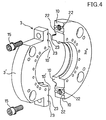
- Fig. 4 shows the backup ring 3, wherein a pair of diagonal projections 22, 22 are formed on the cut surfaces 10, 10 and a pair of diagonal grooves 23, 23 are formed on the facing cut surfaces 10', 10', which are mutually fit.
- the diagonal projections 22 and 22 are not parallel with each other and having a tapered shape.
- the diagonal grooves 23 and 23 are correspondingly non-parallel and having a tapered shape.
- These diagonal projections 22, 22 and diagonal grooves 23, 23 are not parallel with the axial line A. They are not in parallel with the radial direction R, either. Therefore, fitting the diagonal projections 22 and the diagonal grooves 23 will position pieces 3' and 3" in the axial and radial directions, establishing a high-precision ring.
- the backup ring 3 has a faucet structure 51 attached, as shown in Fig. 1, from which a core protrudes.
- Fig. 5 shows the set ring 4.
- Fig. 5A is its partially enlarged view.
- a pair of diagonal projections 46, 46 are formed on the cut surfaces 10, 10 and a pair of diagonal grooves 45, 45 are formed on the facing cut surfaces 10' and 10', which are mutually fit.
- the diagonal grooves 45 and 45 are not parallel with each other and having a tapered shape.
- the diagonal projections 46 and 46 are correspondingly non-parallel and having a tapered shape.
- These diagonal grooves 45, 45 and diagonal projections 46, 46 are not in parallel with the axial line A. They are not in parallel with the radial direction R, either. Therefore, fitting the diagonal grooves 45 and the diagonal projections 46 will position pieces 4' and 4" in the axial and radial directions, establishing a high-precision ring.
- Fig. 6 shows an inside type casing, wherein the projections 20 and grooves 21 similar to those of the rotary seal ring 1 are formed on the cut surfaces 10, 10.
- the projections 20 and grooves 21 or the diagonal projections 22 and grooves 23 described above may be processed in high precision by wire-EDM, therefore a configuration with dramatically high-precision may be established compared with the conventional configuration employing the pin and engaging hole.
- the configuration of the non-rotary seal ring 2 will be described next.
- the non-rotary seal ring 2 is Carbon-made, the non-rotary seal ring 2 formed in one piece first is divided into two by season cracking. Because of it, a minutely jagged surface is naturally formed on the cut surfaces of the non-rotary seal ring 2, that allows joining of the two pieces without developing deviation. Also, a level difference does not develop in the seal surfaces.
- the assembly operation will be more efficient if the rubber band 5 is adhered to one of the pieces by a double-sided adhesive tape before the assembly starts, and the other side of the double-sided adhesive tape is pealed to adhere the rubber band 5 to the other piece when it is joined.
- the ring Upon the rubber band 5 is set, the ring is configured to form by mounting said set ring 4 from its top.
- the rubber band 5 bears the fastening force from this set ring 4 as well as functioning as a buffer material that prevents the Carbon-made set ring 4 from being scratched.
Landscapes
- Engineering & Computer Science (AREA)
- General Engineering & Computer Science (AREA)
- Mechanical Engineering (AREA)
- Mechanical Sealing (AREA)
Applications Claiming Priority (2)
| Application Number | Priority Date | Filing Date | Title |
|---|---|---|---|
| JP2003364580A JP4271005B2 (ja) | 2003-10-24 | 2003-10-24 | 分割型環状体及び分割型メカニカルシール |
| JP2003364580 | 2003-10-24 |
Publications (1)
| Publication Number | Publication Date |
|---|---|
| EP1526311A1 true EP1526311A1 (de) | 2005-04-27 |
Family
ID=34386544
Family Applications (1)
| Application Number | Title | Priority Date | Filing Date |
|---|---|---|---|
| EP04024536A Withdrawn EP1526311A1 (de) | 2003-10-24 | 2004-10-14 | Gleitringdichtung |
Country Status (3)
| Country | Link |
|---|---|
| US (1) | US20050087931A1 (de) |
| EP (1) | EP1526311A1 (de) |
| JP (1) | JP4271005B2 (de) |
Cited By (2)
| Publication number | Priority date | Publication date | Assignee | Title |
|---|---|---|---|---|
| DE102007002644A1 (de) * | 2007-01-12 | 2008-07-17 | Aumüller, Hermann | Stevenrohrabdichtung |
| CN103201544A (zh) * | 2010-10-29 | 2013-07-10 | 炭研密封精工株式会社 | 机械密封件 |
Families Citing this family (17)
| Publication number | Priority date | Publication date | Assignee | Title |
|---|---|---|---|---|
| JP2007040316A (ja) * | 2005-07-29 | 2007-02-15 | Smc Corp | 環状磁石およびそれを用いた流体圧シリンダ |
| JP4509008B2 (ja) * | 2005-11-10 | 2010-07-21 | 株式会社岩田製作所 | シャフト固定具 |
| US7708283B2 (en) * | 2006-05-17 | 2010-05-04 | A.W. Chesterton Company | Mechanical seal assembly |
| US8091897B2 (en) * | 2006-05-17 | 2012-01-10 | A.W. Chesterton Company | Mechanical seal assembly |
| JP5199342B2 (ja) * | 2008-05-09 | 2013-05-15 | イーグル工業株式会社 | 分割型メカニカルシール |
| US7921921B2 (en) * | 2008-09-24 | 2011-04-12 | Baker Hughes Incorporated | Downhole backup system and method |
| JP2010127416A (ja) * | 2008-11-28 | 2010-06-10 | Fujisawa Maruzen:Kk | 回転軸のシール構造 |
| US8544497B2 (en) * | 2009-10-30 | 2013-10-01 | Emd Millipore Corporation | Fluid transfer device and system |
| CN102713377A (zh) * | 2010-03-26 | 2012-10-03 | 伊格尔工业股份有限公司 | 机械密封装置 |
| US20120306161A1 (en) * | 2011-05-31 | 2012-12-06 | Crown Iron Works Company | Multi-segment seal retainer for rotating shafts |
| JP5999770B2 (ja) * | 2013-03-09 | 2016-09-28 | イーグル工業株式会社 | 分割型メカニカルシール |
| JP6283023B2 (ja) * | 2013-04-08 | 2018-02-21 | イーグルブルグマンジャパン株式会社 | メカニカルシール |
| WO2015072275A1 (ja) | 2013-11-12 | 2015-05-21 | イーグル工業株式会社 | 分割型メカニカルシール |
| EP3106719A1 (de) * | 2014-02-10 | 2016-12-21 | EagleBurgmann Japan Co., Ltd. | Mechanisches werkzeug |
| MX2022015045A (es) | 2020-06-05 | 2023-04-26 | Chesterton A W Co | Sellos secundarios activados externamente en sellos mecanicos divididos. |
| US12152677B2 (en) | 2020-06-05 | 2024-11-26 | A.W. Chesterton Company | System and method for optimizing a fluid environment in split mechanical seals |
| CN117419162A (zh) * | 2023-11-02 | 2024-01-19 | 四川博正达机械密封件科技有限公司 | 一种密封环及其散热加工工艺 |
Citations (3)
| Publication number | Priority date | Publication date | Assignee | Title |
|---|---|---|---|---|
| US4423878A (en) * | 1982-03-29 | 1984-01-03 | Escue Jesse W | Sealing assembly, kit and method for rotatable shafts |
| US4580793A (en) * | 1984-07-26 | 1986-04-08 | Bronson & Bratton | Split rotary seal ring and method for making same |
| US5370401A (en) | 1992-06-30 | 1994-12-06 | Eg&G Sealol, Inc. | Antirotational and axial force component in a pusher seal assembly and tool for wear installation |
-
2003
- 2003-10-24 JP JP2003364580A patent/JP4271005B2/ja not_active Expired - Lifetime
-
2004
- 2004-10-14 US US10/965,318 patent/US20050087931A1/en not_active Abandoned
- 2004-10-14 EP EP04024536A patent/EP1526311A1/de not_active Withdrawn
Patent Citations (3)
| Publication number | Priority date | Publication date | Assignee | Title |
|---|---|---|---|---|
| US4423878A (en) * | 1982-03-29 | 1984-01-03 | Escue Jesse W | Sealing assembly, kit and method for rotatable shafts |
| US4580793A (en) * | 1984-07-26 | 1986-04-08 | Bronson & Bratton | Split rotary seal ring and method for making same |
| US5370401A (en) | 1992-06-30 | 1994-12-06 | Eg&G Sealol, Inc. | Antirotational and axial force component in a pusher seal assembly and tool for wear installation |
Cited By (3)
| Publication number | Priority date | Publication date | Assignee | Title |
|---|---|---|---|---|
| DE102007002644A1 (de) * | 2007-01-12 | 2008-07-17 | Aumüller, Hermann | Stevenrohrabdichtung |
| CN103201544A (zh) * | 2010-10-29 | 2013-07-10 | 炭研密封精工株式会社 | 机械密封件 |
| CN103201544B (zh) * | 2010-10-29 | 2015-04-22 | 炭研密封精工株式会社 | 机械密封件 |
Also Published As
| Publication number | Publication date |
|---|---|
| JP4271005B2 (ja) | 2009-06-03 |
| JP2005127436A (ja) | 2005-05-19 |
| US20050087931A1 (en) | 2005-04-28 |
Similar Documents
| Publication | Publication Date | Title |
|---|---|---|
| EP1526311A1 (de) | Gleitringdichtung | |
| JP2003531347A (ja) | スプリットメカニカルシール | |
| EP2273164B1 (de) | Geteilte mechanische dichtung | |
| US5913521A (en) | Rotating seal ring component kit for a mechanical split seal | |
| JPH04231775A (ja) | 分割メカニカル端面シール | |
| EP2024670A2 (de) | Mechanische versiegelungsanordnung | |
| WO2012090968A1 (ja) | 一軸偏心ねじポンプ | |
| US6550779B2 (en) | Mechanical split seal | |
| AU733449B2 (en) | A rotating seal ring component kit for a mechanical split seal | |
| JP6681642B2 (ja) | 分割型メカニカルシール | |
| WO1989002999A1 (en) | Mechanical seal | |
| US10935141B2 (en) | Apparatus and method for unitizing split ring halves with holder halves of a clamshell split ring mechanical seal face assembly | |
| JP3072094B1 (ja) | メカニカルシ―ル | |
| US4905366A (en) | Method of installing a positive bearing housing seal | |
| WO2006070725A1 (ja) | 軸封装置 | |
| JP6742232B2 (ja) | 回り止め機構 | |
| CN219767454U (zh) | 一种用于管件定心的装置 | |
| US20250314302A1 (en) | Cartridge Seal | |
| WO2013038792A1 (ja) | メカニカルシール | |
| JP4447339B2 (ja) | 分割型メカニカルシール | |
| JPH0771614A (ja) | 軸封装置 | |
| JPH0771615A (ja) | 軸封装置 | |
| JPH11107988A (ja) | セグメント型無給水軸封装置 |
Legal Events
| Date | Code | Title | Description |
|---|---|---|---|
| PUAI | Public reference made under article 153(3) epc to a published international application that has entered the european phase |
Free format text: ORIGINAL CODE: 0009012 |
|
| AK | Designated contracting states |
Kind code of ref document: A1 Designated state(s): AT BE BG CH CY CZ DE DK EE ES FI FR GB GR HU IE IT LI LU MC NL PL PT RO SE SI SK TR |
|
| AX | Request for extension of the european patent |
Extension state: AL HR LT LV MK |
|
| AKX | Designation fees paid | ||
| STAA | Information on the status of an ep patent application or granted ep patent |
Free format text: STATUS: THE APPLICATION IS DEEMED TO BE WITHDRAWN |
|
| 18D | Application deemed to be withdrawn |
Effective date: 20051028 |
|
| REG | Reference to a national code |
Ref country code: DE Ref legal event code: 8566 |