EP1526351B1 - Procédé de fabrication d'un échangeur de chaleur et échangeur de chaleur fabriqué selon un tel procédé - Google Patents
Procédé de fabrication d'un échangeur de chaleur et échangeur de chaleur fabriqué selon un tel procédé Download PDFInfo
- Publication number
- EP1526351B1 EP1526351B1 EP04021691.3A EP04021691A EP1526351B1 EP 1526351 B1 EP1526351 B1 EP 1526351B1 EP 04021691 A EP04021691 A EP 04021691A EP 1526351 B1 EP1526351 B1 EP 1526351B1
- Authority
- EP
- European Patent Office
- Prior art keywords
- fluid
- fluid distribution
- outflow
- collecting means
- fluid inflow
- Prior art date
- Legal status (The legal status is an assumption and is not a legal conclusion. Google has not performed a legal analysis and makes no representation as to the accuracy of the status listed.)
- Expired - Lifetime
Links
- 238000000034 method Methods 0.000 title claims description 17
- 238000004519 manufacturing process Methods 0.000 title claims description 7
- 239000012530 fluid Substances 0.000 claims description 208
- 238000009826 distribution Methods 0.000 claims description 105
- 238000004378 air conditioning Methods 0.000 claims description 6
- 238000005304 joining Methods 0.000 claims description 6
- 239000000853 adhesive Substances 0.000 claims description 2
- 230000001070 adhesive effect Effects 0.000 claims description 2
- 238000003780 insertion Methods 0.000 claims 2
- 230000037431 insertion Effects 0.000 claims 2
- 230000006835 compression Effects 0.000 claims 1
- 238000007906 compression Methods 0.000 claims 1
- 229910000679 solder Inorganic materials 0.000 claims 1
- 238000011161 development Methods 0.000 description 5
- 230000018109 developmental process Effects 0.000 description 5
- 238000005476 soldering Methods 0.000 description 5
- 239000011324 bead Substances 0.000 description 4
- 239000000463 material Substances 0.000 description 3
- 238000003466 welding Methods 0.000 description 2
- 230000006978 adaptation Effects 0.000 description 1
- 238000007792 addition Methods 0.000 description 1
- 238000005452 bending Methods 0.000 description 1
- 238000010276 construction Methods 0.000 description 1
- 230000009969 flowable effect Effects 0.000 description 1
- 239000002184 metal Substances 0.000 description 1
- 238000005192 partition Methods 0.000 description 1
- 238000004080 punching Methods 0.000 description 1
- 239000003507 refrigerant Substances 0.000 description 1
Images

Classifications
-
- F—MECHANICAL ENGINEERING; LIGHTING; HEATING; WEAPONS; BLASTING
- F28—HEAT EXCHANGE IN GENERAL
- F28F—DETAILS OF HEAT-EXCHANGE AND HEAT-TRANSFER APPARATUS, OF GENERAL APPLICATION
- F28F9/00—Casings; Header boxes; Auxiliary supports for elements; Auxiliary members within casings
- F28F9/02—Header boxes; End plates
- F28F9/04—Arrangements for sealing elements into header boxes or end plates
- F28F9/16—Arrangements for sealing elements into header boxes or end plates by permanent joints, e.g. by rolling
- F28F9/18—Arrangements for sealing elements into header boxes or end plates by permanent joints, e.g. by rolling by welding
-
- F—MECHANICAL ENGINEERING; LIGHTING; HEATING; WEAPONS; BLASTING
- F28—HEAT EXCHANGE IN GENERAL
- F28D—HEAT-EXCHANGE APPARATUS, NOT PROVIDED FOR IN ANOTHER SUBCLASS, IN WHICH THE HEAT-EXCHANGE MEDIA DO NOT COME INTO DIRECT CONTACT
- F28D1/00—Heat-exchange apparatus having stationary conduit assemblies for one heat-exchange medium only, the media being in contact with different sides of the conduit wall, in which the other heat-exchange medium is a large body of fluid, e.g. domestic or motor car radiators
- F28D1/02—Heat-exchange apparatus having stationary conduit assemblies for one heat-exchange medium only, the media being in contact with different sides of the conduit wall, in which the other heat-exchange medium is a large body of fluid, e.g. domestic or motor car radiators with heat-exchange conduits immersed in the body of fluid
- F28D1/04—Heat-exchange apparatus having stationary conduit assemblies for one heat-exchange medium only, the media being in contact with different sides of the conduit wall, in which the other heat-exchange medium is a large body of fluid, e.g. domestic or motor car radiators with heat-exchange conduits immersed in the body of fluid with tubular conduits
- F28D1/053—Heat-exchange apparatus having stationary conduit assemblies for one heat-exchange medium only, the media being in contact with different sides of the conduit wall, in which the other heat-exchange medium is a large body of fluid, e.g. domestic or motor car radiators with heat-exchange conduits immersed in the body of fluid with tubular conduits the conduits being straight
- F28D1/0535—Heat-exchange apparatus having stationary conduit assemblies for one heat-exchange medium only, the media being in contact with different sides of the conduit wall, in which the other heat-exchange medium is a large body of fluid, e.g. domestic or motor car radiators with heat-exchange conduits immersed in the body of fluid with tubular conduits the conduits being straight the conduits having a non-circular cross-section
- F28D1/05366—Assemblies of conduits connected to common headers, e.g. core type radiators
- F28D1/05383—Assemblies of conduits connected to common headers, e.g. core type radiators with multiple rows of conduits or with multi-channel conduits
-
- F—MECHANICAL ENGINEERING; LIGHTING; HEATING; WEAPONS; BLASTING
- F28—HEAT EXCHANGE IN GENERAL
- F28F—DETAILS OF HEAT-EXCHANGE AND HEAT-TRANSFER APPARATUS, OF GENERAL APPLICATION
- F28F9/00—Casings; Header boxes; Auxiliary supports for elements; Auxiliary members within casings
- F28F9/02—Header boxes; End plates
- F28F9/0202—Header boxes having their inner space divided by partitions
- F28F9/0204—Header boxes having their inner space divided by partitions for elongated header box, e.g. with transversal and longitudinal partitions
- F28F9/0214—Header boxes having their inner space divided by partitions for elongated header box, e.g. with transversal and longitudinal partitions having only longitudinal partitions
-
- F—MECHANICAL ENGINEERING; LIGHTING; HEATING; WEAPONS; BLASTING
- F28—HEAT EXCHANGE IN GENERAL
- F28F—DETAILS OF HEAT-EXCHANGE AND HEAT-TRANSFER APPARATUS, OF GENERAL APPLICATION
- F28F9/00—Casings; Header boxes; Auxiliary supports for elements; Auxiliary members within casings
- F28F9/02—Header boxes; End plates
- F28F9/0246—Arrangements for connecting header boxes with flow lines
- F28F9/0248—Arrangements for sealing connectors to header boxes
-
- F—MECHANICAL ENGINEERING; LIGHTING; HEATING; WEAPONS; BLASTING
- F28—HEAT EXCHANGE IN GENERAL
- F28F—DETAILS OF HEAT-EXCHANGE AND HEAT-TRANSFER APPARATUS, OF GENERAL APPLICATION
- F28F2275/00—Fastening; Joining
- F28F2275/14—Fastening; Joining by using form fitting connection, e.g. with tongue and groove
Definitions
- the present invention relates to a method for the simplified production of a device for exchanging heat, in particular for motor vehicles, as well as to a device and an air conditioning system produced accordingly.
- heat exchangers for motor vehicles are generally manufactured by preassembling their main components to form a block and soldering them in this form in a furnace.
- the closing pipes or connecting pieces required for operation are only soldered or welded in a subsequent work step.
- connection pipes on the heat exchanger block In order to rationalize production and reduce production costs, it is desirable to save this additional operation of subsequent soldering or welding of the connecting pipes. For this purpose, sufficient pre-fixing of the connection pipes on the heat exchanger block must be ensured before soldering.
- the U.S. 6,129,146 A discloses a heat exchanger with a collecting device and with a connecting pipe which has beads for holding the connecting pipe in an opening of the collecting device.
- the invention is therefore based on the object of creating a method for the simplified production of a device for exchanging heat, which allows connection pipes to be pre-fixed on the heat exchanger, so that the heat exchanger can be manufactured already fully assembled by means of material connections, such as in particular soldered connections, without the need for subsequent additional work steps such as soldering or welding the connection pipes. It is also the task to create a corresponding device and an air conditioning system with such a device.
- the object is achieved according to the invention by a method according to claim 1.
- the device produced according to the invention is the subject matter of claim 6.
- the air conditioning system is the subject matter of claim 14.
- Preferred process additions, embodiments, further developments and uses are the subject matter of the subclaims.
- the method according to the invention for producing a device for exchanging heat, in particular for motor vehicles comprises at least the following steps: In one step, at least one fluid flow device is joined together in a force and / or form-fluid manner with at least two fluid distribution and / or collection devices.
- At least one fluid inflow or outflow device with at least one fluid distribution and / or collection device in the region of at least one opening provided in the fluid distribution and / or collection device which has at least one having limiting shaped element, wherein the shape of the shaped element is geometrically matched or adapted to the shape of the fluid inflow or outflow device that by the relative movement of at least one end portion of at least one fluid inflow or outflow device relative to the shaped element, at least one connecting surface between the Molded element and at least part of the end section of the fluid inflow or outflow device is created, with the fluid inflow or outflow device being self-locking pre-fixed to the fluid distribution and / or collecting device by the size and / or shape of this connecting surface.
- self-locking is understood to mean that the devices which are prefixed with respect to one another are substantially prefixed in a form-fitting and / or force-fitting manner solely through their mutual contact.
- An example of this is the nesting of a cone in a hollow cone with essentially the same cone angle.
- a delimiting shaped element in the area of the opening in the fluid distribution and / or collecting device is understood within the scope of the invention to be an element which, on the one hand, geometrically delimits the opening and, on the other hand, protrudes out of the opening or into the opening with respect to a plane spanned by the opening cross-section , such as an edge, a bead, a passage or the like.
- geometrical coordination or adaptation is understood to mean that at least two geometrical surfaces are adapted to one another in such a way that when these surfaces are joined, contact takes place not only at individual points but at least in an area of at least one surface segment.
- the essentially gas-tight and liquid-tight fastening of the pre-fixed device for exchanging heat with respect to the environment takes place via material connections.
- this material connection takes place, in particular, but not exclusively, via soldered connections, welded connections and / or adhesive connections.
- At least one fluid inflow or outflow connection with at least one shaped element in the area of a longitudinal and / or end-side opening is at least a fluid distribution and / or collection device positively and / or non-positively joined together.
- the self-locking pre-fixation of at least one fluid inflow or outflow device on at least one shaped element of a fluid distribution and / or collecting device in the form of a positive and / or non-positive connection takes place in that at least one fluid inflow or outflow device has a Has an end section with an outer cross section that tapers substantially towards the end, which is inserted into at least one shaped element of the fluid distribution and / or collection device with an inner cross section that widens substantially outward.
- the self-locking pre-fixation of at least one fluid inflow or outflow device on at least one shaped element of a fluid distribution and / or collecting device in the form of a positive and / or non-positive connection takes place in that at least one fluid inflow or outflow device has a Has an end section with an inner cross section that essentially widens towards the end, which is plugged onto at least one shaped element of the fluid distribution and / or collection device with an outer cross section that essentially tapers outwards.
- the self-locking pre-fixing of at least one fluid inflow or outflow device on at least one shaped element of a fluid distribution and / or collecting device in the form of a form-fitting and / or non-positive connection is achieved in that at least one fluid inflow or outflow device
- the drainage device has an end section which is essentially conical towards the end and which is inserted into at least one essentially internally conical shaped element of the fluid distribution and / or collection devices.
- the self-locking pre-fixing of at least one fluid inflow or outflow device on at least one shaped element of a fluid distribution and / or collecting device takes place in the form of a positive and / or non-positive connection in that at least one fluid inflow or outflow device
- the drainage device has an end section which is essentially internally conical toward the end and which is pushed onto at least one essentially conical shaped element of the fluid distribution and / or collection device.
- the self-locking pre-fixation of at least one fluid inflow or outflow device to at least one shaped element of a fluid distribution and / or collection device is preferably carried out at least partially by at least one form-locking element, such as in particular, but not exclusively, hooks, eyes, threads, recesses and / or projections . It is possible for such hooks, eyes, threads or the like to be arranged either on the fluid distribution and / or collecting device or on the fluid inflow and / or outflow device. However, it is also possible to arrange such form-locking elements on both elements, for example two intermeshing threads. Bayonet-like closures or the like are also present for the purposes of the present invention.
- the fluid distribution and / or collection devices and the end sections of the fluid inflow and outflow devices can preferably be twisted into one another, hooked or the like.
- At least one molded element of at least one fluid distribution and / or collection device and / or at least one end section of the fluid inflow or outflow device is preferably manufactured with suitable sizes and shape tolerances.
- the length or diameter tolerances of the shaped elements of the fluid distribution and / or collection devices and of the end sections of the fluid supply or drainage devices are ⁇ 0.8 mm, preferably ⁇ 0.1 mm and particularly preferably ⁇ 0.05 mm.
- the angular tolerances of the preferably conical end sections of the fluid inflow and outflow devices, as well as the preferably inner conical shaped elements of the fluid distribution and / or collecting devices are ⁇ 4 degrees, preferably ⁇ 1 degrees and particularly preferably ⁇ 0.5 degrees.
- a predetermined end position of the fluid inflow or outflow device with respect to the shaped element of the fluid distributing and / or collecting device results, so that the The outer end of the fluid inflow or outflow device is preferably essentially flush with the inner end of the molded element of at least one fluid distribution and / or collection device.
- the joining together of at least one fluid inflow and outflow device with at least one fluid distribution and / or collection device takes place via a press connection, preferably a cone press connection.
- the fluid throughflow devices, the fluid distribution and / or collecting devices and the fluid inflow and outflow device are preferably produced by punching out and bending parts of a one-piece flat metal sheet.
- the invention is further directed to a device for exchanging heat, in particular for motor vehicles, which is produced according to one of the methods described above and has at least one first inflow device and at least two fluid distribution and / or collecting devices, at least one fluid flow device and at least one Fluid drainage device, wherein at least one opening is provided in at least one fluid distribution and / or collection device, which opening has at least one delimiting shaped element.
- the shape of the feature geometrically matched or adapted to the shape of the fluid inflow or outflow device in such a way that the fluid inflow or outflow device, which is joined to the opening of the fluid distribution and / or collecting device, has at least one connecting surface to at least one Has shaped element of the fluid distribution and / or collecting device, the size and / or shape of this connecting surface pre-fixing the fluid inflow or outflow device in a self-locking manner via a form-fitting and / or non-positive connection to the fluid distribution and / or collecting device.
- prefixing is understood to mean that the final strength of the finished device has not yet been achieved, but rather a mutual hold is achieved which enables final fastening or fixing, for example by soldering and the like.
- At least one fluid inflow or outflow device has an end section with an outer cross section that tapers substantially towards the end, the end section being in at least one shaped element of at least one fluid distribution and / or collecting device, the one on the end section geometrically coordinated or adapted, substantially expanding outward, inner cross-section is inserted.
- an end section is to be understood as such a section which is at least partially connected to the fluid distribution and / or collection device.
- At least one fluid inflow or outflow device has an end section with an inner cross section that essentially widens towards the end, which is plugged onto at least one shaped element of at least one fluid distribution and / or collection device.
- the shaped element of the fluid distribution and / or collection device has a shape that is geometrically matched to the end section or adapted, essentially outwardly tapering outer cross-section.
- the tapering or the widening can run continuously, but it can also take place in steps or in the form of individual beads.
- At least one fluid inflow or outflow device has an end section which is essentially conical towards the end and which, in at least one shaped element, has at least one fluid distribution and / or collection device that has an inner cone that is geometrically matched or adapted to the end section is inserted.
- At least one fluid inflow or outflow device has an end section which is essentially internally conical towards the end and which is attached to at least one shaped element of at least one fluid distribution and / or collection device that has a cone that is geometrically matched or adapted to the end section is.
- the cone angle of at least one end section of the fluid inflow or outflow device and / or at least one shaped element of the fluid distribution and / or collection devices is less than 10 degrees, preferably less than 5 degrees and particularly preferably between 2 and 3 degrees.
- the compressed length of the connecting surface of at least one end section of a fluid inflow or outflow device with at least one shaped element of a fluid distribution and / or collecting device is between 0.5 mm and 10 mm, preferably between 1 mm and 5 mm and particularly preferably 2.5 mm and 3.5 mm.
- At least one fluid inflow or outflow device and / or at least one shaped element of a fluid distribution and / or collecting device has at least one form-locking element on.
- the form-fit element is selected from a group of form-fit elements which in particular, but not exclusively, has hooks, eyes, threads, recesses and / or projections.
- the form-fit elements preferably engage in at least one shaped element of a fluid distribution and / or collection device or a region of a fluid inflow or outflow device.
- the cross section of at least one opening in at least one fluid distribution and / or collection device has a geometric shape that is taken from a group that has essentially circular, elliptical, rectangular shapes and mixed shapes of these shapes.
- the opening is preferably designed in the form of an elongated hole.
- Another characteristic size of the opening in at least one fluid distribution and / or collecting device is the hydraulic diameter D, which is defined by four times the freely flowable cross-sectional area divided by the circumference of the opening.
- the hydraulic diameter D is between 5 and 20 mm, preferably between 10 and 16 mm and particularly preferably between 13 and 14 mm.
- At least one shaped element in the area of an opening of the fluid distribution and / or collection devices is preferably designed as an outwardly or inwardly directed passage.
- At least one opening of a fluid distribution and / or collection device is arranged on the longitudinal side.
- At least one front opening is provided in at least one fluid distribution and / or collection device.
- the shape of the end section of the fluid inflow or outflow device is based on the shaped element of the end opening in the Fluid distribution and / or collecting device geometrically coordinated or adapted so that the end section joined to the shaped element of the front opening of the fluid distributing and / or collecting device has a connecting surface to the shaped element, whereby the size and / or shape of this connecting surface allows the fluid supply or .
- -Discharge device or a form-fitting and / or non-positive connection on the fluid distribution and / or collection device is pre-fixed in a self-locking manner.
- At least one front opening is provided in at least one fluid distribution and / or collection device and at least one end section of a fluid inflow or outflow device is also designed as a cover.
- this cover plate when assembling this cover plate, it is preferably placed or applied to the fluid distribution and / or collection device in such a way that, in the assembled state, a tight seal against the environment is created.
- two longitudinally adjacent tubes 3a and 3b can be seen, which have an essentially semicircular cross-section with an essentially flat bottom plate, which is not visible, the flat bottom plate being the heat exchanger body, which is arranged under tubes 3a and 3b and formed from a large number of essentially rectangular flat tubes 9 is facing.
- the long sides of the flat tubes 9 are arranged essentially perpendicular to the base plate and their longer transverse sides lie in planes parallel to the end face of the tubes 3a and 3b. The latter form the upper fluid distribution and / or collection devices.
- tubes 4a and 4b with essentially the same shape with respect to tubes 3a and 3b can be seen, which also face the heat exchanger body with their base plate and form the lower fluid distribution and / or collection devices.
- a substantially tubular fluid inflow or outflow device 6 is inserted with a substantially rectangular end section with rounded corners into a substantially rectangular elongated hole in the fluid distribution and / or collecting device 3a with correspondingly rounded corners near the pipe end face.
- the fluid inflow or outflow device 6 is bent in the vicinity of its end section pushed into the fluid distribution and / or collecting device 3a at an obtuse angle in the direction of the bottom plates of the tubes 3a and 3b and after about two thirds of its length with respect to the pushed in End bent back at essentially the same obtuse angle.
- Another essentially tubular fluid outflow or inflow device 8 is inserted into the fluid distribution and / or collecting device 3b on the lower end face with a cover formed at one end and angled three times essentially by 90 degrees. First in the vicinity of the end cover in the direction of the fluid inflow or outflow device 6 parallel to the base plate of the fluid distribution and / or collecting devices 3a and 3b, further at some distance from the longitudinal side of the pipe 3a towards this, whereby this is in the exemplary embodiment with respect to the tube 6 thinner tube 8 extends below the former.
- the open ends of the fluid inflow and outflow devices 6 and 8 are thus level with the underside of the manifold 3a approximately in the first third of its longitudinal side, each have a circumferential bead at a certain distance from the end and are essentially the same distance from the longitudinal side of the tube 3a spaced. Furthermore, the free ends of the tubes 3a, 3b, 4a, 4b are closed with semicircular covers that are matched to their cross-section.
- partition walls are provided which essentially prevent the fluid or refrigerant from flowing through in the longitudinal direction I of the device.
- the plurality of essentially rectangular flat tubes 9 are in non-visible passages in the flat sides of the fluid distribution. and / or collecting devices 3a and 3b or 4a and 4b, which form the throughflow devices of the heat exchanger device.
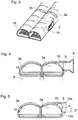
- Fig. 2 shows a perspective partial representation of the in Fig. 1 shown device with the upper fluid distribution and / or collecting devices 3a and 3b and the essentially tubular fluid inflow and outflow devices 6 and 8 inserted therein as described above.
- a cover formed at one end of the fluid outflow and inflow device 8 12 or closure with a semicircular shape matched to the cross section of the tube 3b is plugged into the fluid distribution and / or collection devices 3b on the front side.
- the shaped element that delimits the opening and is formed around the longitudinal opening in the form of a substantially rectangular elongated hole in the fluid distribution and / or collecting devices 3a with rounded corners is designed as an outwardly directed passage 10 with an inner cross section tapering into the pipe interior, in which the Fluid inflow or outflow device 6 can be inserted with its end section correspondingly matched in shape, which has an outer cross section tapering towards the end.
- Fig. 3 shows a further perspective detailed representation of the fluid distribution and / or collecting devices 3a and 3b, the fluid outflow and / or inflow device 8 with the semicircular cover 12 and the fluid inflow and outflow device 6 with the end section matched to the elongated hole 5 being removed are, whereby a view into the interior of the fluid distribution and / or collection devices 3a and 3b is possible.
- the flat-tube-shaped throughflow devices 9 can be pushed through the passages 16 arranged in the essentially flat undersides of the fluid distribution and / or collection devices 3a and 3b.
- the end section of the fluid inflow or outflow device 6 with a correspondingly matched shape and essentially tapering towards the end can be pushed into the essentially elongated lateral opening 5 with rounded corners.
- the inside of the passage is through the removed fluid inflow and outflow device 6 10 can be seen with the inwardly tapering inner cross-section, which is the connecting surface between the fluid inflow and or outflow device 6 and the fluid distribution device that is necessary for pre-fixing the fluid inflow and outflow device 6 and the fluid distribution and / or collecting device 3a. and / or collecting device 3a forms.
- Fig. 4 shows a cross-sectional view of the fluid collection and / or distribution devices 3a and 3b.
- the longitudinal opening 5 delimited by the passage 10 tapering into the pipe interior can be seen, into which the outwardly tapering end section of the fluid inflow or outflow device 6 is inserted becomes.
- the flow devices 9 partially shown in the rectangular longitudinal section show individual flat tubes which are inserted through the passages 16 essentially perpendicular to the direction in which the fluid outflow or inflow device 6 is inserted into the fluid collection and distribution device 3a.
- the fluid inflow or outflow device 6 preferably only protrudes into the interior of the fluid collecting and / or distributing device 3a to such an extent that a collision with the throughflow devices 9 is prevented.
- FIG. 8 shows a further view of the cross-sectional representation from FIG Fig. 4 .
- the edge of the passage 10a is inclined by 2 degrees in relation to the center perpendicular S of the opening cross-sectional plane towards S, in which the outer edge of the end section of the fluid inflow or outflow device 6, the has a substantially equal inclination outwardly of the tube, is pressed in for pre-fixing.
Landscapes
- Engineering & Computer Science (AREA)
- Physics & Mathematics (AREA)
- Thermal Sciences (AREA)
- Mechanical Engineering (AREA)
- General Engineering & Computer Science (AREA)
- Air-Conditioning For Vehicles (AREA)
- Heat-Exchange Devices With Radiators And Conduit Assemblies (AREA)
Claims (14)
- Procédé de fabrication d'un dispositif (1) servant à l'échange de chaleur, en particulier pour des véhicules automobiles, ledit procédé comprenant les étapes suivantes :- l'assemblage, par action de force et par complémentarité de forme, d'au moins un dispositif de circulation de fluide (9) avec au moins deux dispositifs distributeurs et / ou collecteurs de fluide (3a, 3b),- l'assemblage, par action de force et par complémentarité de forme, d'au moins un dispositif d'entrée ou de sortie de fluide (6) avec au moins l'un des dispositifs distributeurs et / ou collecteurs de fluide (3a, 3b) au moins au nombre de deux, ledit assemblage étant réalisé dans la zone d'au moins une ouverture (5) prévue dans le dispositif distributeur et / ou collecteur de fluide (3a, 3b), laquelle ouverture présente au moins un élément de moulage limitatif, où la forme de l'élément de moulage est géométriquement harmonisée ou adaptée par rapport à la forme du dispositif d'entrée ou de sortie de fluide (6), de manière telle que sous l'effet du mouvement relatif d'un segment d'extrémité du dispositif d'entrée ou de sortie de fluide (6), par rapport à l'élément de moulage, il se crée au moins une surface de liaison entre l'élément de moulage et au moins une partie du segment d'extrémité du dispositif d'entrée ou de sortie de fluide (6), où, en fonction de la taille et / ou de la forme de cette surface de liaison, le dispositif d'entrée ou de sortie de fluide (6) est préfixé de manière autobloquante sur le dispositif distributeur et / ou collecteur de fluide (3a, 3b), où le mouvement relatif se produit par insertion du dispositif d'entrée ou de sortie de fluide (6), dans l'ouverture (5),- la fixation du dispositif préfixé (1) qui sert à l'échange de chaleur par rapport au milieu ambiant, ladite fixation étant réalisée pratiquement de façon étanche aux gaz et / ou aux liquides et mise en œuvre au moyen d'au moins un assemblage obtenu par continuité de matière, où- la préfixation autobloquante du dispositif d'entrée ou de sortie de fluide (6), sur l'élément de moulage de l'ouverture (5) du dispositif distributeur et / ou collecteur de fluide (3a, 3b), se produit sous la forme d'un assemblage obtenu par action de force, par le fait que le segment d'extrémité du dispositif d'entrée ou de sortie de fluide (6) présente une section extérieure allant en diminuant pratiquement jusqu'à l'extrémité, et par le fait que ledit segment d'extrémité est inséré dans l'élément de moulage du dispositif distributeur et / ou collecteur de fluide (3a, 3b), en ayant une section intérieure s'élargissant pratiquement vers l'extérieur, et où- la préfixation autobloquante du dispositif d'entrée ou de sortie de fluide (6), sur l'élément de moulage du dispositif distributeur et / ou collecteur de fluide (3a, 3b), se produit sous la forme d'un assemblage obtenu par action de force et par complémentarité de forme, par le fait que le segment d'extrémité du dispositif d'entrée ou de sortie de fluide (6) présente une forme de cône pratiquement jusqu'à l'extrémité, et par le fait que ledit segment d'extrémité est inséré dans l'élément de moulage du dispositif distributeur et / ou collecteur de fluide (3a, 3b), ledit élément de moulage étant en forme de cône à l'intérieur.
- Procédé selon la revendication 1, caractérisé en ce que l'assemblage obtenu par continuité de matière est réalisé en effectuant des assemblages brasés, des assemblages soudés et / ou des assemblages collés.
- Procédé selon l'une des revendications précédentes, caractérisé en ce que l'ouverture (5) est prévue sur le côté longitudinal et / ou sur le côté frontal du dispositif distributeur et / ou collecteur de fluide (3a, 3b), où le dispositif d'entrée ou de sortie de fluide (6) est assemblé, par complémentarité de forme et par action de force, avec l'élément de moulage, dans la zone de l'ouverture (5) du dispositif distributeur et / ou collecteur de fluide (3a, 3b), ladite ouverture étant située sur le côté longitudinal et / ou sur le côté frontal dudit dispositif.
- Procédé selon au moins l'une quelconque des revendications précédentes, caractérisé en ce que la fabrication de l'élément de moulage du dispositif distributeur et / ou collecteur de fluide (3a, 3b), ainsi que du segment d'extrémité du dispositif d'entrée ou de sortie de fluide (6), est mise en œuvre avec des tolérances de taille et de forme, qui sont appropriées, grâce à quoi, au moment de l'assemblage du segment d'extrémité du dispositif d'entrée ou de sortie de fluide (6) avec l'élément de moulage du dispositif distributeur et / ou collecteur de fluide (3a, 3b), il en résulte une position de fin de course prédéfinie du dispositif d'entrée ou de sortie de fluide (6), par rapport à l'élément de moulage du dispositif distributeur et / ou collecteur de fluide (3a, 3b), de préférence, mais pas de façon exclusive, de manière telle que l'extrémité extérieure du dispositif d'entrée ou de sortie de fluide (6) se termine en étant à fleur de l'extrémité intérieure de l'élément de moulage du dispositif distributeur et / ou collecteur de fluide (3a, 3b).
- Procédé selon au moins l'une quelconque des revendications précédentes, caractérisé en ce que l'assemblage du dispositif d'entrée ou de sortie de fluide (6) avec le dispositif distributeur et / ou collecteur de fluide (3a, 3b) est mis en œuvre en effectuant un assemblage réalisé par compression, de préférence un assemblage réalisé par compression conique.
- Dispositif (1) servant à l'échange de chaleur, en . particulier pour des véhicules automobiles, dispositif qui est fabriqué selon au moins l'une quelconque des revendications précédentes et qui comprend :- au moins un dispositif d'entrée de fluide (6),- au moins deux dispositifs distributeurs et / ou collecteurs de fluide (3a, 3b),- au moins un dispositif de circulation de fluide (9) et- au moins un dispositif de sortie de fluide (6), où une ouverture (5) est prévue dans au moins l'un des dispositifs distributeurs et / ou collecteurs de fluide (3a, 3b) au moins au nombre de deux, laquelle ouverture présente au moins un élément de moulage limitatif,caractérisé
en ce que la forme de l'élément de moulage est géométriquement harmonisée ou adaptée par rapport à la forme du dispositif d'entrée ou de sortie de fluide (6), en ce que le dispositif d'entrée ou de sortie de fluide (6) qui, dans la zone de l'ouverture (5) du dispositif distributeur et / ou collecteur de fluide (3a, 3b), est assemblé avec celui-ci, présente au moins une surface de liaison avec l'élément de moulage du dispositif distributeur et / ou collecteur de fluide (3a, 3b), où, en fonction de la taille et / ou de la forme de cette surface de liaison, le dispositif d'entrée ou de sortie de fluide (6), par un assemblage obtenu par action de force et par complémentarité de forme, est préfixé de manière autobloquante sur le dispositif distributeur et / ou collecteur de fluide (3a, 3b), ladite préfixation étant réalisée sous l'effet d'un mouvement relatif se produisant par insertion du dispositif d'entrée ou de sortie de fluide (6), dans l'ouverture (5), où le dispositif d'entrée ou de sortie de fluide (6) présente un segment d'extrémité ayant une section extérieure allant en diminuant pratiquement jusqu'à l'extrémité, lequel segment d'extrémité est inséré dans l'élément de moulage du dispositif distributeur et / ou collecteur de fluide (3a, 3b), lequel élément de moulage présente une section intérieure géométriquement harmonisée ou adaptée par rapport au segment d'extrémité, ladite section intérieure s'élargissant pratiquement vers l'extérieur, et où le segment d'extrémité du dispositif d'entrée ou de sortie de fluide (6) présente une forme conique se profilant pratiquement jusqu'à l'extrémité, et ledit segment d'extrémité est inséré dans l'élément de moulage des dispositifs distributeurs et / ou collecteurs de fluide (3a, 3b), lequel élément de moulage présente un cône intérieur géométriquement harmonisé ou adapté par rapport au segment d'extrémité. - Dispositif (1) selon la revendication 6, caractérisé en ce que le dispositif d'entrée ou de sortie de fluide (6) et / ou l'élément de moulage du dispositif distributeur et / ou collecteur de fluide (3a, 3b) présente au moins l'un des éléments à complémentarité de forme, comme en particulier, mais pas de façon exclusive, des crochets, des œillets, des pas de vis, des évidements et / ou des parties en saillie, qui s'engagent dans l'élément de moulage du dispositif distributeur et / ou collecteur de fluide (3a, 3b) ou bien dans au moins une zone du dispositif d'entrée ou de sortie de fluide (6).
- Dispositif (1) selon l'une des revendications précédentes 6 ou 7, caractérisé en ce que l'ouverture (5) située dans le dispositif distributeur et / ou collecteur de fluide (3a, 3b) est configurée sous la forme d'un trou oblong (5).
- Dispositif (1) selon l'une des revendications précédentes 6 ou 7, caractérisé en ce que la forme de la section de l'ouverture (5) située dans le dispositif distributeur et / ou collecteur de fluide (3a, 3b) est choisie dans un groupe qui présente des formes pratiquement circulaires, pratiquement elliptiques, pratiquement rectangulaires ainsi que des formes mixtes de ces mêmes formes.
- Dispositif (1) selon l'une quelconque des revendications précédentes 6 à 9, caractérisé en ce que l'élément de moulage est configuré, dans la zone de l'ouverture (5) du dispositif distributeur et / ou collecteur de fluide (3a, 3b), comme un passage (16) dirigé vers l'intérieur ou l'extérieur.
- Dispositif (1) selon l'une quelconque des revendications précédentes 6 à 10, caractérisé en ce que l'ouverture (5) au moins au nombre de un d'au moins l'un des dispositifs distributeurs et / ou collecteurs de fluide (3a, 3b) est disposée sur le côté longitudinal.
- Dispositif (1) selon l'une quelconque des revendications précédentes 6 à 11, caractérisé en ce que l'ouverture (5) est prévue sous la forme d'une ouverture (5) formée dans le dispositif distributeur et / ou collecteur de fluide (3a, 3b) et située sur son côté frontal, où la forme du segment d'extrémité du dispositif d'entrée ou de sortie de fluide (6) est géométriquement harmonisée ou adaptée par rapport à l'élément de moulage de l'ouverture (5) formée dans le dispositif distributeur et / ou collecteur de fluide (3a, 3b) et située sur son côté frontal, de manière telle que le segment d'extrémité, qui est assemblé avec l'élément de moulage de l'ouverture (5) du dispositif distributeur et / ou collecteur de fluide (3a, 3b), ladite ouverture étant située sur le côté frontal dudit dispositif, présente la surface de liaison avec l'élément de moulage, où, en fonction de la taille et / ou de la forme de cette surface de liaison, le dispositif d'entrée ou de sortie de fluide (6), par l'assemblage obtenu par action de force et par complémentarité de forme, est préfixé de manière autobloquante sur le dispositif distributeur et / ou collecteur de fluide (3a, 3b).
- Dispositif (1) selon la revendication 12, caractérisé en ce que le segment d'extrémité du dispositif d'entrée ou de sortie de fluide (6) est configuré comme un couvercle de fermeture.
- Système de climatisation pour un véhicule automobile, ledit système comprenant au moins un dispositif servant à la compression d'air, au moins un premier dispositif servant à l'échange de chaleur, au moins un deuxième dispositif servant à l'échange de chaleur, au moins un dispositif qui commande et / ou règle le système de climatisation, caractérisé en ce que l'on utilise au moins un dispositif servant à l'échange de chaleur, ledit dispositif étant fabriqué selon au moins l'une quelconque des revendications 1 à 5 et présentant les caractéristiques d'au moins l'une quelconque des revendications 6 à 13.
Applications Claiming Priority (2)
| Application Number | Priority Date | Filing Date | Title |
|---|---|---|---|
| DE10349976 | 2003-10-24 | ||
| DE10349976A DE10349976A1 (de) | 2003-10-24 | 2003-10-24 | Verfahren zur vereinfachten Herstellung einer Vorrichtung zum Austausch von Wärme sowie danach hergestellte Vorrichtung |
Publications (3)
| Publication Number | Publication Date |
|---|---|
| EP1526351A2 EP1526351A2 (fr) | 2005-04-27 |
| EP1526351A3 EP1526351A3 (fr) | 2013-04-10 |
| EP1526351B1 true EP1526351B1 (fr) | 2020-08-12 |
Family
ID=34384487
Family Applications (1)
| Application Number | Title | Priority Date | Filing Date |
|---|---|---|---|
| EP04021691.3A Expired - Lifetime EP1526351B1 (fr) | 2003-10-24 | 2004-09-13 | Procédé de fabrication d'un échangeur de chaleur et échangeur de chaleur fabriqué selon un tel procédé |
Country Status (2)
| Country | Link |
|---|---|
| EP (1) | EP1526351B1 (fr) |
| DE (1) | DE10349976A1 (fr) |
Families Citing this family (3)
| Publication number | Priority date | Publication date | Assignee | Title |
|---|---|---|---|---|
| DE102004048767A1 (de) * | 2004-10-05 | 2006-04-06 | Behr Gmbh & Co. Kg | Verfahren zur Herstellung eines Wärmeübertragers |
| DE102006040847A1 (de) * | 2006-08-31 | 2008-03-06 | Behr Gmbh & Co. Kg | Sammelkasten eines Wärmeübertragers |
| EP2098313A1 (fr) * | 2008-03-06 | 2009-09-09 | Delphi Technologies, Inc. | Collecteur d'échangeur thermique et son procédé de fabrication |
Citations (3)
| Publication number | Priority date | Publication date | Assignee | Title |
|---|---|---|---|---|
| JPH10281687A (ja) * | 1997-04-04 | 1998-10-23 | Calsonic Corp | 熱交換器用ヘッダと流体移送用パイプとの接続部 |
| JP2000220990A (ja) * | 1999-01-28 | 2000-08-08 | Sanden Corp | 熱交換器 |
| US6129146A (en) * | 1999-05-17 | 2000-10-10 | Krueger; David L. | Manifold for a brazed radiator |
Family Cites Families (9)
| Publication number | Priority date | Publication date | Assignee | Title |
|---|---|---|---|---|
| FR2238545B1 (fr) * | 1973-07-25 | 1978-10-27 | Chausson Usines Sa | |
| DE3917173C2 (de) * | 1989-05-30 | 1994-08-25 | Showa Aluminium Co Ltd | Verfahren zur Herstellung eines Wärmetauscher-Sammlers |
| JPH0818124B2 (ja) * | 1992-05-22 | 1996-02-28 | 昭和アルミニウム株式会社 | 熱交換器 |
| DE4303219A1 (de) * | 1992-08-06 | 1994-02-10 | Abb Patent Gmbh | Kaltluft-Kältemaschinen-Anlage |
| CH688356A5 (it) * | 1993-07-02 | 1997-08-15 | Abdul Amir Mahdi | Radiatore composto da elementi radianti e membri di supporto collegati per mezzo di accoppiamento forzato. |
| JPH07318289A (ja) * | 1994-05-23 | 1995-12-08 | Nippondenso Co Ltd | 熱交換器 |
| EP1054227A3 (fr) * | 1999-05-19 | 2001-02-28 | Modine Manufacturing Company | Assemblage d'un raccord de tuyau et d'un réservoir et méthode d'assemblage |
| JP2001012892A (ja) * | 1999-06-30 | 2001-01-19 | Bosch Automotive Systems Corp | 熱交換器 |
| JP2001248995A (ja) * | 2000-03-03 | 2001-09-14 | Zexel Valeo Climate Control Corp | 熱交換器 |
-
2003
- 2003-10-24 DE DE10349976A patent/DE10349976A1/de not_active Withdrawn
-
2004
- 2004-09-13 EP EP04021691.3A patent/EP1526351B1/fr not_active Expired - Lifetime
Patent Citations (3)
| Publication number | Priority date | Publication date | Assignee | Title |
|---|---|---|---|---|
| JPH10281687A (ja) * | 1997-04-04 | 1998-10-23 | Calsonic Corp | 熱交換器用ヘッダと流体移送用パイプとの接続部 |
| JP2000220990A (ja) * | 1999-01-28 | 2000-08-08 | Sanden Corp | 熱交換器 |
| US6129146A (en) * | 1999-05-17 | 2000-10-10 | Krueger; David L. | Manifold for a brazed radiator |
Also Published As
| Publication number | Publication date |
|---|---|
| EP1526351A2 (fr) | 2005-04-27 |
| EP1526351A3 (fr) | 2013-04-10 |
| DE10349976A1 (de) | 2005-05-25 |
Similar Documents
| Publication | Publication Date | Title |
|---|---|---|
| DE69600516T2 (de) | Wärmetauscher und Verfahren zu dessen Herstellung | |
| DE19603016A1 (de) | Wärmetauscher | |
| EP1703243A1 (fr) | Échangeur de chaleur avec tubes et ailettes et procédé de fabrication | |
| DE19543986A1 (de) | Wärmetauscher und ein Verfahren zur Herstellung eines Wärmetauschers | |
| EP1333219A1 (fr) | Raccord à action rapide | |
| DE4442040A1 (de) | Wärmetauscher mit einem Sammelrohr | |
| DE3203356A1 (de) | Waermeaustauscher | |
| EP1537369A1 (fr) | Condenseur d'agent refrigerant, notamment pour installations de conditionnement d'air d'automobile | |
| EP1376043B1 (fr) | Echangeur de chaleur avec diffuseur | |
| EP1500892A2 (fr) | Echangeur de chaleur pour véhicules | |
| DE10033070A1 (de) | Kühler für Kraftfahrzeuge sowie Herstellungsverfahren | |
| WO2005085738A1 (fr) | Dispositif d'echange de chaleur et procede de fabrication | |
| DE19750067B4 (de) | Verfahren zum Fügen eines Bauteils an einen Hohlkörper und dadurch herstellbarer Halter-Rohrelement-Komplex | |
| DE19680345C5 (de) | Filteranordnung | |
| EP1526351B1 (fr) | Procédé de fabrication d'un échangeur de chaleur et échangeur de chaleur fabriqué selon un tel procédé | |
| DE19609722B4 (de) | Verfahren zum Verbinden zweier metallischer Profile, insbesondere zweier stranggepreßter Aluminiumprofilteile | |
| DE69903241T2 (de) | Wärmetauscher, insbesondere verflüssiger für kraftfahrzeug und verfahren zu dessen herstellung | |
| DE29704913U1 (de) | Wärmetauscher | |
| DE102006002932A1 (de) | Wärmetauscher und Herstellungsverfahren für Wärmetauscher | |
| EP1668304B1 (fr) | Unite d'echange thermique pour vehicules automobiles | |
| EP0108958B1 (fr) | Raccordement de tubes métalliques d'échangeurs de chaleur avec le fond d'un boîte à eau | |
| DE102006040848A1 (de) | Wärmeübertrager, insbesondere Gaskühler | |
| DE102011075955A1 (de) | Sammelkasten eines Wärmeübertragers | |
| EP1479996B1 (fr) | Raccord de tuyaux pour échangeur de chaleur, notamment radiateurs pour véhicules automobiles | |
| EP1926961B1 (fr) | Echangeur thermique, en particulier refroidisseur a gaz |
Legal Events
| Date | Code | Title | Description |
|---|---|---|---|
| PUAI | Public reference made under article 153(3) epc to a published international application that has entered the european phase |
Free format text: ORIGINAL CODE: 0009012 |
|
| AK | Designated contracting states |
Kind code of ref document: A2 Designated state(s): AT BE BG CH CY CZ DE DK EE ES FI FR GB GR HU IE IT LI LU MC NL PL PT RO SE SI SK TR |
|
| AX | Request for extension of the european patent |
Extension state: AL HR LT LV MK |
|
| PUAL | Search report despatched |
Free format text: ORIGINAL CODE: 0009013 |
|
| AK | Designated contracting states |
Kind code of ref document: A3 Designated state(s): AT BE BG CH CY CZ DE DK EE ES FI FR GB GR HU IE IT LI LU MC NL PL PT RO SE SI SK TR |
|
| AX | Request for extension of the european patent |
Extension state: AL HR LT LV MK |
|
| RIC1 | Information provided on ipc code assigned before grant |
Ipc: F28D 1/053 20060101ALI20130307BHEP Ipc: F28F 9/04 20060101AFI20130307BHEP Ipc: F28F 9/02 20060101ALI20130307BHEP |
|
| 17P | Request for examination filed |
Effective date: 20131010 |
|
| RBV | Designated contracting states (corrected) |
Designated state(s): AT BE BG CH CY CZ DE DK EE ES FI FR GB GR HU IE IT LI LU MC NL PL PT RO SE SI SK TR |
|
| AKX | Designation fees paid |
Designated state(s): DE FR |
|
| RAP1 | Party data changed (applicant data changed or rights of an application transferred) |
Owner name: MAHLE BEHR GMBH & CO. KG |
|
| 17Q | First examination report despatched |
Effective date: 20150601 |
|
| STAA | Information on the status of an ep patent application or granted ep patent |
Free format text: STATUS: EXAMINATION IS IN PROGRESS |
|
| RIC1 | Information provided on ipc code assigned before grant |
Ipc: F28D 1/053 20060101ALI20200115BHEP Ipc: F28F 9/02 20060101ALI20200115BHEP Ipc: F28F 9/18 20060101ALI20200115BHEP Ipc: F28F 9/04 20060101AFI20200115BHEP |
|
| GRAP | Despatch of communication of intention to grant a patent |
Free format text: ORIGINAL CODE: EPIDOSNIGR1 |
|
| STAA | Information on the status of an ep patent application or granted ep patent |
Free format text: STATUS: GRANT OF PATENT IS INTENDED |
|
| INTG | Intention to grant announced |
Effective date: 20200228 |
|
| RIN1 | Information on inventor provided before grant (corrected) |
Inventor name: SEEWALD, WOLFGANG Inventor name: STORZ, WERNER Inventor name: JUNG, MATTHIAS Inventor name: FISCHER, EWALD |
|
| GRAS | Grant fee paid |
Free format text: ORIGINAL CODE: EPIDOSNIGR3 |
|
| GRAJ | Information related to disapproval of communication of intention to grant by the applicant or resumption of examination proceedings by the epo deleted |
Free format text: ORIGINAL CODE: EPIDOSDIGR1 |
|
| GRAL | Information related to payment of fee for publishing/printing deleted |
Free format text: ORIGINAL CODE: EPIDOSDIGR3 |
|
| STAA | Information on the status of an ep patent application or granted ep patent |
Free format text: STATUS: EXAMINATION IS IN PROGRESS |
|
| GRAP | Despatch of communication of intention to grant a patent |
Free format text: ORIGINAL CODE: EPIDOSNIGR1 |
|
| STAA | Information on the status of an ep patent application or granted ep patent |
Free format text: STATUS: GRANT OF PATENT IS INTENDED |
|
| INTC | Intention to grant announced (deleted) | ||
| RIN1 | Information on inventor provided before grant (corrected) |
Inventor name: JUNG, MATTHIAS Inventor name: STORZ, WERNER Inventor name: FISCHER, EWALD Inventor name: SEEWALD, WOLFGANG |
|
| GRAA | (expected) grant |
Free format text: ORIGINAL CODE: 0009210 |
|
| STAA | Information on the status of an ep patent application or granted ep patent |
Free format text: STATUS: THE PATENT HAS BEEN GRANTED |
|
| INTG | Intention to grant announced |
Effective date: 20200619 |
|
| RIN1 | Information on inventor provided before grant (corrected) |
Inventor name: SEEWALD, WOLFGANG Inventor name: FISCHER, EWALD Inventor name: STORZ, WERNER Inventor name: JUNG, MATTHIAS |
|
| AK | Designated contracting states |
Kind code of ref document: B1 Designated state(s): DE FR |
|
| REG | Reference to a national code |
Ref country code: DE Ref legal event code: R096 Ref document number: 502004015872 Country of ref document: DE |
|
| PGFP | Annual fee paid to national office [announced via postgrant information from national office to epo] |
Ref country code: DE Payment date: 20201118 Year of fee payment: 17 |
|
| REG | Reference to a national code |
Ref country code: DE Ref legal event code: R097 Ref document number: 502004015872 Country of ref document: DE |
|
| PLBE | No opposition filed within time limit |
Free format text: ORIGINAL CODE: 0009261 |
|
| STAA | Information on the status of an ep patent application or granted ep patent |
Free format text: STATUS: NO OPPOSITION FILED WITHIN TIME LIMIT |
|
| 26N | No opposition filed |
Effective date: 20210514 |
|
| PG25 | Lapsed in a contracting state [announced via postgrant information from national office to epo] |
Ref country code: FR Free format text: LAPSE BECAUSE OF NON-PAYMENT OF DUE FEES Effective date: 20201012 |
|
| REG | Reference to a national code |
Ref country code: DE Ref legal event code: R119 Ref document number: 502004015872 Country of ref document: DE |
|
| PG25 | Lapsed in a contracting state [announced via postgrant information from national office to epo] |
Ref country code: DE Free format text: LAPSE BECAUSE OF NON-PAYMENT OF DUE FEES Effective date: 20220401 |