EP1526351A2 - Procédé de fabrication d'un échangeur de chaleur et échangeur de chaleur fabriqué selon un tel procédé - Google Patents
Procédé de fabrication d'un échangeur de chaleur et échangeur de chaleur fabriqué selon un tel procédé Download PDFInfo
- Publication number
- EP1526351A2 EP1526351A2 EP04021691A EP04021691A EP1526351A2 EP 1526351 A2 EP1526351 A2 EP 1526351A2 EP 04021691 A EP04021691 A EP 04021691A EP 04021691 A EP04021691 A EP 04021691A EP 1526351 A2 EP1526351 A2 EP 1526351A2
- Authority
- EP
- European Patent Office
- Prior art keywords
- fluid
- fluid distribution
- fluidverteil
- particular according
- section
- Prior art date
- Legal status (The legal status is an assumption and is not a legal conclusion. Google has not performed a legal analysis and makes no representation as to the accuracy of the status listed.)
- Granted
Links
Images

Classifications
-
- F—MECHANICAL ENGINEERING; LIGHTING; HEATING; WEAPONS; BLASTING
- F28—HEAT EXCHANGE IN GENERAL
- F28F—DETAILS OF HEAT-EXCHANGE AND HEAT-TRANSFER APPARATUS, OF GENERAL APPLICATION
- F28F9/00—Casings; Header boxes; Auxiliary supports for elements; Auxiliary members within casings
- F28F9/02—Header boxes; End plates
- F28F9/04—Arrangements for sealing elements into header boxes or end plates
- F28F9/16—Arrangements for sealing elements into header boxes or end plates by permanent joints, e.g. by rolling
- F28F9/18—Arrangements for sealing elements into header boxes or end plates by permanent joints, e.g. by rolling by welding
-
- F—MECHANICAL ENGINEERING; LIGHTING; HEATING; WEAPONS; BLASTING
- F28—HEAT EXCHANGE IN GENERAL
- F28D—HEAT-EXCHANGE APPARATUS, NOT PROVIDED FOR IN ANOTHER SUBCLASS, IN WHICH THE HEAT-EXCHANGE MEDIA DO NOT COME INTO DIRECT CONTACT
- F28D1/00—Heat-exchange apparatus having stationary conduit assemblies for one heat-exchange medium only, the media being in contact with different sides of the conduit wall, in which the other heat-exchange medium is a large body of fluid, e.g. domestic or motor car radiators
- F28D1/02—Heat-exchange apparatus having stationary conduit assemblies for one heat-exchange medium only, the media being in contact with different sides of the conduit wall, in which the other heat-exchange medium is a large body of fluid, e.g. domestic or motor car radiators with heat-exchange conduits immersed in the body of fluid
- F28D1/04—Heat-exchange apparatus having stationary conduit assemblies for one heat-exchange medium only, the media being in contact with different sides of the conduit wall, in which the other heat-exchange medium is a large body of fluid, e.g. domestic or motor car radiators with heat-exchange conduits immersed in the body of fluid with tubular conduits
- F28D1/053—Heat-exchange apparatus having stationary conduit assemblies for one heat-exchange medium only, the media being in contact with different sides of the conduit wall, in which the other heat-exchange medium is a large body of fluid, e.g. domestic or motor car radiators with heat-exchange conduits immersed in the body of fluid with tubular conduits the conduits being straight
- F28D1/0535—Heat-exchange apparatus having stationary conduit assemblies for one heat-exchange medium only, the media being in contact with different sides of the conduit wall, in which the other heat-exchange medium is a large body of fluid, e.g. domestic or motor car radiators with heat-exchange conduits immersed in the body of fluid with tubular conduits the conduits being straight the conduits having a non-circular cross-section
- F28D1/05366—Assemblies of conduits connected to common headers, e.g. core type radiators
- F28D1/05383—Assemblies of conduits connected to common headers, e.g. core type radiators with multiple rows of conduits or with multi-channel conduits
-
- F—MECHANICAL ENGINEERING; LIGHTING; HEATING; WEAPONS; BLASTING
- F28—HEAT EXCHANGE IN GENERAL
- F28F—DETAILS OF HEAT-EXCHANGE AND HEAT-TRANSFER APPARATUS, OF GENERAL APPLICATION
- F28F9/00—Casings; Header boxes; Auxiliary supports for elements; Auxiliary members within casings
- F28F9/02—Header boxes; End plates
- F28F9/0202—Header boxes having their inner space divided by partitions
- F28F9/0204—Header boxes having their inner space divided by partitions for elongated header box, e.g. with transversal and longitudinal partitions
- F28F9/0214—Header boxes having their inner space divided by partitions for elongated header box, e.g. with transversal and longitudinal partitions having only longitudinal partitions
-
- F—MECHANICAL ENGINEERING; LIGHTING; HEATING; WEAPONS; BLASTING
- F28—HEAT EXCHANGE IN GENERAL
- F28F—DETAILS OF HEAT-EXCHANGE AND HEAT-TRANSFER APPARATUS, OF GENERAL APPLICATION
- F28F9/00—Casings; Header boxes; Auxiliary supports for elements; Auxiliary members within casings
- F28F9/02—Header boxes; End plates
- F28F9/0246—Arrangements for connecting header boxes with flow lines
- F28F9/0248—Arrangements for sealing connectors to header boxes
-
- F—MECHANICAL ENGINEERING; LIGHTING; HEATING; WEAPONS; BLASTING
- F28—HEAT EXCHANGE IN GENERAL
- F28F—DETAILS OF HEAT-EXCHANGE AND HEAT-TRANSFER APPARATUS, OF GENERAL APPLICATION
- F28F2275/00—Fastening; Joining
- F28F2275/14—Fastening; Joining by using form fitting connection, e.g. with tongue and groove
Definitions
- the present invention relates to a process for simplified production a device for exchanging heat, in particular for motor vehicles, and then a manufactured device.
- connection pipes To streamline manufacturing and reduce production costs, is it would be desirable to have this additional post-anneal operation or welding the connection pipes to save. This requires a sufficient prefixing of the connection pipes on the heat exchanger block the soldering be guaranteed.
- the invention is therefore based on the object, a method for simplified Producing a device for exchanging heat, which allows prefixing of connection pipes on the heat exchanger, so that the heat exchanger already assembled by cohesive Connections, in particular soldering connections can be made, without subsequent additional work steps, such as soldering or welding the connecting pipes would be necessary.
- the object is achieved by a method according to claim 1 solved.
- the device produced according to the invention is the subject of Claim 11.
- Preferred process supplements, embodiments, Further developments and uses are the subject of the dependent claims.
- the inventive method for producing a device for Exchange of heat, especially for motor vehicles includes at least the following steps:
- At least one fluid flow device will force and / or form liquid with at least two Fluidverteil- and / or assembled together.
- a further step takes place the force and / or form-liquid joining of at least one fluid additive or -abpound noticed with at least one Fluidverteil- and / or -sammel adopted in the range of at least one in the Fluidverteil- and / or -means provided opening, which at least one limiting Form element, wherein the shape of the formula element on the shape of the fluid supply and -offflow device geometrically tuned or is adapted that by the relative movement of at least one end portion at least one fluid inflow or outflow device relative to the Form element at least one connection surface between the mold element and at least a portion of the end portion of the fluid inlet or Drainage device is created, wherein by size and / or shape of this connection surface the fluid supply and -auslhneewed to the Fluidverteilund / or -sammel fitted self-locking prefixed.
- Self-locking is understood in the context of the invention that the mutually prefixed facilities essentially solely by their mutual contact positive and / or non-positive prefixed.
- Example of this can be the nesting of a cone in a hollow cone be called with substantially the same cone angle.
- this cohesive connection in particular, but not exclusively, via solder joints, welded joints and / or adhesive joints.
- At least one fluid inlet or outlet connection with at least one Form element in the region of a longitudinal and / or end opening at least a Fluidverteil- and / or-collecting device positive and / or non-positive together.
- the self-locking prefixing of at least one Fluidzu- -discharge device on at least one molding element of a Fluidverteilund / or -sammel adopted in the form of a positive and / or non-positive Compound in that at least one fluid addition or drain device has an end portion with one towards the end substantially having tapered outer cross section, which in at least a mold element of the fluid distribution and / or-collecting device with a inserted substantially outwardly widening inner cross-section becomes.
- the self-locking prefixing of at least one Fluidzu- -discharge device on at least one molding element of a Fluidverteilund / or -sammel adopted in the form of a positive and / or non-positive Compound in that at least one fluid addition or drain device has an end portion with one towards the end substantially having widening inner cross section, which on at least a mold element of the fluid distribution and / or-collecting device with a essentially externally tapered outer cross-section plugged becomes.
- the self-locking prefixing of at least one Fluidzu- -discharge device on at least one molding element of a Fluidverteilund / or -sammel adopted in the form of a positive and / or non-positive Compound in that at least one fluid addition or -discharge means a towards the end substantially conical End portion which, in at least one substantially innenkonusförmiges Form element of Fluidverteil- and / or -ammoll sensibleen is inserted.
- the self-locking prefixing of at least one Fluidzu- -discharge device on at least one molding element of a Fluidverteilund / or -sammel adopted in the form of a positive and / or non-positive Compound in that at least one fluid addition or -discharge means a towards the end substantially innenkonusförmigen End portion which, at least one substantially cone-shaped Form element of Fluidverteil- and / or-collecting device plugged becomes.
- the self-locking prefixing of at least one fluid additive preferably takes place. or drain device on at least one molding element of a fluid distribution and / or -sammel adopted at least partially by at least a form-fitting element, in particular, but not exclusively, hooks, Eyelets, threads, recesses and / or projections. It is possible that such hooks, eyes, threads or the like either at the fluid distribution and / or collection device or at the fluid supply and / or -discharge device are arranged. However, it is also possible to two elements such positive locking elements to arrange, as for Example two interlocking threads. Also lie bayonet-like Closures or the like in the sense of the present invention.
- the Fluidverteil- and / or -ammolle Sket- and/ or -ammolle
- the End portions of the fluid supply and -ausl Sket- and/ or -ammolle
- the production of at least one formula element preferably takes place at least a Fluidverteil- and / or-collecting device and / or at least one End portion of the fluid inflow and outflow means of suitable sizes and shape tolerances.
- the length or diameter tolerances of the form elements of the fluid distribution and / or collecting devices and the end sections of the fluid supply or -ausl shall be ⁇ 0.8 mm, preferably ⁇ 0.1 mm and especially preferably ⁇ 0.05 mm.
- the angular tolerances of the preferred cone-shaped End portions of the fluid supply and -abhne adopteden, as well as the preferably inner cone-shaped form elements of Fluidverteil- and / or - collecting devices are ⁇ 4 degrees, preferably ⁇ 1 degree and especially preferably ⁇ 0.5 degrees.
- the fluid flow devices the Fluidverteil- and / or -sammel
- the fluid inflow or -discharge device by punching and bending parts of a one-piece produced flat metal sheet.
- the invention further relates to a device for exchanging heat, in particular for motor vehicles, directed to any of the above Process is prepared and at least a first inflow device and at least two Fluidverteil- and / or -sammel landmarken, at least one fluid flow device and at least a fluid drainage device, wherein in at least one fluid distribution and / or -sammel nails is provided at least one opening, which has at least one limiting shape element.
- At least one fluid additive or -abl adopted an end portion with a towards the end substantially widening inner cross section, which on at least a shaped element of at least one Fluidverteil- and / or -sammel nails is attached.
- the shaped element of the fluid distribution and / or-collecting means on the end portion geometrically coordinated or adjusted, essentially to the outside tapered outer cross section on.
- the rejuvenation or expansion can be continuous, it can However, also stepwise or done in the form of individual beads.
- At least one fluid additive or -abl adopted a towards the end substantially conical End portion, which in at least one molding element at least a Fluidverteil- and / or -ammolle driven, one on the end portion has geometrically tuned or adapted inner cone, is inserted.
- At least one fluid inflow or outflow device preferably has a towards the end substantially inwardly tapered end portion, which at least on a form elements of at least one Fluidverteilund / or -sammel adopted, the one on the end section geometrically matched or adapted cone is plugged.
- the cone angle of at least one end section of the fluid supply is or downflow device and / or at least one formula element of the fluid distribution and / or collection devices less than 10 degrees, preferably less as 5 degrees, and more preferably between 2 and 3 degrees.
- the compressed length of the connecting surface of at least one end portion a fluid supply and -offflow device with at least one molding element a Fluidverteil- and / or-collecting device lies between 0.5 mm and 10 mm, preferably between 1 mm and 5 mm and especially preferably 2.5 mm and 3.5 mm.
- At least one fluid additive or drainage device and / or at least one molding element of a fluid distribution and / or-collecting device at least one positive locking element on.
- the positive-locking element is a group of positive-locking elements selected, in particular, but not exclusively, hooks, Has eyelets, threads, recesses and / or projections.
- the cross section at least an opening in at least one Fluidverteil- and / or Collecting a geometric shape, taken from a group is the substantially circular, elliptical, rectangular shapes and has mixed forms of these forms.
- the opening is preferred formed in the form of a slot.
- the hydraulic diameter D is defined by four times the freely permeable cross-sectional area divided by the size of the opening.
- the hydraulic Diameter D is between 5 and 20 mm, preferably between 10 and 16 mm and more preferably between 13 and 14 mm.
- At least one molding element in the region of an opening of the Fluidverteil- and / or Collection devices preferably as outwardly or inwardly directed Draft designed.
- At least one opening a Fluidverteil- and / or-collecting device arranged longitudinally.
- At least one end-side Opening in at least one Fluidverteil- and / or -ammolle realized intended.
- the shape of the end portion of the fluid inlet or Discharge device on the molding element of the frontal opening in the Fluidverteil- and / or-collecting device geometrically tuned or adjusted so that the with the form element of the end opening of the fluid distribution and / or collecting means assembled end portion a Has connecting surface to the mold element, wherein by size and / or Form of this connection surface via the fluid supply and -abl esters over a positive and / or non-positive connection to the Fluidverteil- and / or -sammel fitted self-locking prefixed.
- At least one end-side Opening in at least one Fluidverteil- and / or -ammolle realized provided and further at least one end portion of a Fluidzu- or Drainage designed as a cover. It is preferred during assembly of this end cover so on the Fluidverteilund / or -sammel adopted put on or applied, that in assembled Condition a tight seal against the environment arises.
- At least one according to at least one of the claims 1 to 10 produced device for exchanging heat according to at least one of claims 11 to 23 in an air conditioning system for a motor vehicle with at least one means for compressing air, at least a first means for exchanging heat, at least a second device for exchanging heat, at least one device, which controls the air conditioning and / or regulates used.
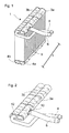
- Fig. 1 is a device 1 according to the invention for the exchange of heat, in particular for motor vehicles, shown in perspective.
- two longitudinally adjacent tubes 3a and 3b can be seen, which have a substantially semicircular cross-section with a non-visible, substantially flat bottom plate, wherein the plane Bottom plate arranged under the tubes 3a and 3b, from a Variety of substantially rectangular flat tubes 9 formed heat exchanger body is facing.
- the longitudinal sides of the flat tubes 9 are in the Essentially arranged perpendicular to the bottom plate and its longer Transverse sides lie in parallel planes to the end face of the tubes 3a and 3b. The latter form the upper Fluidverteil- and / or -ammolle Roaden.
- a substantially tubular fluid inflow and outflow device 6 is with a substantially rectangular end portion with rounded corners is in a substantially rectangular slot in the Fluidverteil- and / or -sammel Anlagen 3a with correspondingly rounded corners in the vicinity the tube end side inserted longitudinally.
- the fluid addition or outflow device 6 is close to its in the Fluidverteil- and / or - collecting device 3a inserted end portion in a blunt Angle in the direction of the bottom plates of the tubes 3a and 3b bent and after about two thirds of its length with respect to the inserted end to the im Essentially the same blunt angle bent back.
- Another substantially tubular Fluidab- or Inlet 8 is at the lower end with one at one end trained end cap in the Fluidverteil- and / or Collection device 3b inserted and three times substantially at 90 degrees angled.
- Partitions provided which a flow through the fluid or refrigerant In the longitudinal direction I of the device substantially prevent.
- the plurality is substantially rectangular flat tubes 9 in invisible passages in the flat Side fluid distribution and / or collection devices 3a and 3b and 4a, respectively and 4b, which are the flow devices of the heat exchanger device form.
- Fig. 2 shows a partial perspective view of the device shown in Fig. 1 with the upper fluid distribution and / or collection devices 3a and 3b and the insert therein as described above substantially tubular fluid inflow and outflow devices 6 and 8.
- An on a End of the Fluidab- and / infuser 8 trained lid 12th or closure with a matched to the cross section of the tube 3b semi-circular shape is the front side in the Fluidverteil- and / or -means 3b inserted.
- the opening delimiting form element is as outwardly directed passage 10 configured with an inner cross-section tapering into the tube interior, in which the fluid supply and discharge means 6 with their corresponding in the form of tuned end section, one towards the end having tapered outer cross section, can be inserted.
- Fig. 3 shows a further perspective detail of the Fluidverteilund / or -sammelinraumen 3a and 3b, wherein the Fluidab- and or -fill device 8 with the semicircular cover 12 and the Fluidzu- and or drain-6 with the tuned to the slot 5 end portion are removed, whereby a look inside the Fluidverteilund / or Collection means 3a and 3b is possible.
- the flat tubular flow devices 9 are pushed.
- FIG. 4 shows a cross-sectional view of the fluid collection and / or distribution facilities 3a and 3b.
- On the right side of the fluid collection and / or Distribution device 3a is the longitudinal side, from the inside of the tube tapered passage 10 limited opening 5 to recognize, in which the outwardly tapered end portion of Fluidzu- or -Drain device 6 is inserted.
- the in rectangular longitudinal section partially shown flow devices 9 show individual flat tubes, substantially perpendicular to the direction in which the fluid discharge or Zupound Mother 6 inserted into the fluid collection and distribution device 3a is inserted through the passages 16.
- the protrudes Fluidzu- or discharge device 6 only so far into the interior of the fluid collection and / or distribution device 3a into that a collision with the Flow devices 9 is prevented.
- Fig. 5 shows another view of the cross-sectional view of Fig. 4. How resulting from the geometries drawn in the right margin of the figure, is the edge of the passage 10a by 2 degrees from the perpendicular bisector S of the opening cross-sectional plane inwardly inclined to S, in the Outer edge of the end portion of the fluid supply and -ausllig 6, the having a substantially equal slope downhole, for prefixing is pressed.
Landscapes
- Engineering & Computer Science (AREA)
- Physics & Mathematics (AREA)
- Thermal Sciences (AREA)
- Mechanical Engineering (AREA)
- General Engineering & Computer Science (AREA)
- Air-Conditioning For Vehicles (AREA)
- Heat-Exchange Devices With Radiators And Conduit Assemblies (AREA)
Applications Claiming Priority (2)
| Application Number | Priority Date | Filing Date | Title |
|---|---|---|---|
| DE10349976 | 2003-10-24 | ||
| DE10349976A DE10349976A1 (de) | 2003-10-24 | 2003-10-24 | Verfahren zur vereinfachten Herstellung einer Vorrichtung zum Austausch von Wärme sowie danach hergestellte Vorrichtung |
Publications (3)
| Publication Number | Publication Date |
|---|---|
| EP1526351A2 true EP1526351A2 (fr) | 2005-04-27 |
| EP1526351A3 EP1526351A3 (fr) | 2013-04-10 |
| EP1526351B1 EP1526351B1 (fr) | 2020-08-12 |
Family
ID=34384487
Family Applications (1)
| Application Number | Title | Priority Date | Filing Date |
|---|---|---|---|
| EP04021691.3A Expired - Lifetime EP1526351B1 (fr) | 2003-10-24 | 2004-09-13 | Procédé de fabrication d'un échangeur de chaleur et échangeur de chaleur fabriqué selon un tel procédé |
Country Status (2)
| Country | Link |
|---|---|
| EP (1) | EP1526351B1 (fr) |
| DE (1) | DE10349976A1 (fr) |
Cited By (1)
| Publication number | Priority date | Publication date | Assignee | Title |
|---|---|---|---|---|
| EP2098313A1 (fr) * | 2008-03-06 | 2009-09-09 | Delphi Technologies, Inc. | Collecteur d'échangeur thermique et son procédé de fabrication |
Families Citing this family (2)
| Publication number | Priority date | Publication date | Assignee | Title |
|---|---|---|---|---|
| DE102004048767A1 (de) * | 2004-10-05 | 2006-04-06 | Behr Gmbh & Co. Kg | Verfahren zur Herstellung eines Wärmeübertragers |
| DE102006040847A1 (de) * | 2006-08-31 | 2008-03-06 | Behr Gmbh & Co. Kg | Sammelkasten eines Wärmeübertragers |
Family Cites Families (12)
| Publication number | Priority date | Publication date | Assignee | Title |
|---|---|---|---|---|
| FR2238545B1 (fr) * | 1973-07-25 | 1978-10-27 | Chausson Usines Sa | |
| DE3917173C2 (de) * | 1989-05-30 | 1994-08-25 | Showa Aluminium Co Ltd | Verfahren zur Herstellung eines Wärmetauscher-Sammlers |
| JPH0818124B2 (ja) * | 1992-05-22 | 1996-02-28 | 昭和アルミニウム株式会社 | 熱交換器 |
| DE4303219A1 (de) * | 1992-08-06 | 1994-02-10 | Abb Patent Gmbh | Kaltluft-Kältemaschinen-Anlage |
| CH688356A5 (it) * | 1993-07-02 | 1997-08-15 | Abdul Amir Mahdi | Radiatore composto da elementi radianti e membri di supporto collegati per mezzo di accoppiamento forzato. |
| JPH07318289A (ja) * | 1994-05-23 | 1995-12-08 | Nippondenso Co Ltd | 熱交換器 |
| JP3774024B2 (ja) * | 1997-04-04 | 2006-05-10 | カルソニックカンセイ株式会社 | 熱交換器用ヘッダと流体移送用パイプとの接続部 |
| JP2000220990A (ja) * | 1999-01-28 | 2000-08-08 | Sanden Corp | 熱交換器 |
| US6129146A (en) * | 1999-05-17 | 2000-10-10 | Krueger; David L. | Manifold for a brazed radiator |
| EP1054227A3 (fr) * | 1999-05-19 | 2001-02-28 | Modine Manufacturing Company | Assemblage d'un raccord de tuyau et d'un réservoir et méthode d'assemblage |
| JP2001012892A (ja) * | 1999-06-30 | 2001-01-19 | Bosch Automotive Systems Corp | 熱交換器 |
| JP2001248995A (ja) * | 2000-03-03 | 2001-09-14 | Zexel Valeo Climate Control Corp | 熱交換器 |
-
2003
- 2003-10-24 DE DE10349976A patent/DE10349976A1/de not_active Withdrawn
-
2004
- 2004-09-13 EP EP04021691.3A patent/EP1526351B1/fr not_active Expired - Lifetime
Cited By (1)
| Publication number | Priority date | Publication date | Assignee | Title |
|---|---|---|---|---|
| EP2098313A1 (fr) * | 2008-03-06 | 2009-09-09 | Delphi Technologies, Inc. | Collecteur d'échangeur thermique et son procédé de fabrication |
Also Published As
| Publication number | Publication date |
|---|---|
| EP1526351A3 (fr) | 2013-04-10 |
| EP1526351B1 (fr) | 2020-08-12 |
| DE10349976A1 (de) | 2005-05-25 |
Similar Documents
| Publication | Publication Date | Title |
|---|---|---|
| DE69600516T2 (de) | Wärmetauscher und Verfahren zu dessen Herstellung | |
| DE4019899C1 (fr) | ||
| DE4442040A1 (de) | Wärmetauscher mit einem Sammelrohr | |
| EP1846718B1 (fr) | Echangeur thermique | |
| DE10338527A1 (de) | Kältemittelkondensator, insbesondere für Kraftfahrzeug-Klimaanlagen | |
| DE10237769A1 (de) | Wärmeaustauscher und Verfahren zur Herstellung | |
| DE3316960C2 (de) | Fügestutzen für Unrundrohre in einem Tankboden für Wärmetauscher und Werkzeug zu dessen Herstellung | |
| WO2005085738A1 (fr) | Dispositif d'echange de chaleur et procede de fabrication | |
| DE3028096A1 (de) | Anpassungsverfahren eines metallrohres insbesondere fuer waermetauscher u.dgl. | |
| DE19750067B4 (de) | Verfahren zum Fügen eines Bauteils an einen Hohlkörper und dadurch herstellbarer Halter-Rohrelement-Komplex | |
| EP1384968B1 (fr) | Echangeur de chaleur et procédé de fabrication associé | |
| EP1526351A2 (fr) | Procédé de fabrication d'un échangeur de chaleur et échangeur de chaleur fabriqué selon un tel procédé | |
| EP3364091A1 (fr) | Raccord | |
| DE29704913U1 (de) | Wärmetauscher | |
| DE102006002932A1 (de) | Wärmetauscher und Herstellungsverfahren für Wärmetauscher | |
| EP3175195B1 (fr) | Échangeur de chaleur et procédé de fabrication de l'échangeur de chaleur | |
| EP1771697B1 (fr) | Echangeur thermique, boite destinee a recevoir un fluide pour un echangeur thermique, et procede de production de cette boite | |
| EP2087304A1 (fr) | Boîtier destiné à contenir un liquide destiné à un échangeur thermique, procédé de réalisation d'un tel boîtier, et échangeur thermique | |
| DE102006002789A1 (de) | Flachrohr, Wärmetauscher und Herstellungsverfahren für Wärmetauscher | |
| DE4112431A1 (de) | Rohr-boden-verbindung eines waermetauschers, verfahren zur herstellung einer solchen rohr-boden-verbindung und anwendung | |
| EP2017021B1 (fr) | Procédé de fabrication d'ouvertures dans un élément de sol et élément de sol pouvant être fabriqué selon ce procédé | |
| DE10132485A1 (de) | Sammelkasten für einen Wärmetauscher und Verfahren zu dessen Herstellung | |
| EP1479996B1 (fr) | Raccord de tuyaux pour échangeur de chaleur, notamment radiateurs pour véhicules automobiles | |
| DE102013204735A1 (de) | Flachrohr und ein Wärmeübertrager mit einem solchen Flachrohr | |
| DE102013100366A1 (de) | Doppelwandiges Abgasvolumen und entsprechendes Herstellungsverfahren |
Legal Events
| Date | Code | Title | Description |
|---|---|---|---|
| PUAI | Public reference made under article 153(3) epc to a published international application that has entered the european phase |
Free format text: ORIGINAL CODE: 0009012 |
|
| AK | Designated contracting states |
Kind code of ref document: A2 Designated state(s): AT BE BG CH CY CZ DE DK EE ES FI FR GB GR HU IE IT LI LU MC NL PL PT RO SE SI SK TR |
|
| AX | Request for extension of the european patent |
Extension state: AL HR LT LV MK |
|
| PUAL | Search report despatched |
Free format text: ORIGINAL CODE: 0009013 |
|
| AK | Designated contracting states |
Kind code of ref document: A3 Designated state(s): AT BE BG CH CY CZ DE DK EE ES FI FR GB GR HU IE IT LI LU MC NL PL PT RO SE SI SK TR |
|
| AX | Request for extension of the european patent |
Extension state: AL HR LT LV MK |
|
| RIC1 | Information provided on ipc code assigned before grant |
Ipc: F28D 1/053 20060101ALI20130307BHEP Ipc: F28F 9/04 20060101AFI20130307BHEP Ipc: F28F 9/02 20060101ALI20130307BHEP |
|
| 17P | Request for examination filed |
Effective date: 20131010 |
|
| RBV | Designated contracting states (corrected) |
Designated state(s): AT BE BG CH CY CZ DE DK EE ES FI FR GB GR HU IE IT LI LU MC NL PL PT RO SE SI SK TR |
|
| AKX | Designation fees paid |
Designated state(s): DE FR |
|
| RAP1 | Party data changed (applicant data changed or rights of an application transferred) |
Owner name: MAHLE BEHR GMBH & CO. KG |
|
| 17Q | First examination report despatched |
Effective date: 20150601 |
|
| STAA | Information on the status of an ep patent application or granted ep patent |
Free format text: STATUS: EXAMINATION IS IN PROGRESS |
|
| RIC1 | Information provided on ipc code assigned before grant |
Ipc: F28D 1/053 20060101ALI20200115BHEP Ipc: F28F 9/02 20060101ALI20200115BHEP Ipc: F28F 9/18 20060101ALI20200115BHEP Ipc: F28F 9/04 20060101AFI20200115BHEP |
|
| GRAP | Despatch of communication of intention to grant a patent |
Free format text: ORIGINAL CODE: EPIDOSNIGR1 |
|
| STAA | Information on the status of an ep patent application or granted ep patent |
Free format text: STATUS: GRANT OF PATENT IS INTENDED |
|
| INTG | Intention to grant announced |
Effective date: 20200228 |
|
| RIN1 | Information on inventor provided before grant (corrected) |
Inventor name: SEEWALD, WOLFGANG Inventor name: STORZ, WERNER Inventor name: JUNG, MATTHIAS Inventor name: FISCHER, EWALD |
|
| GRAS | Grant fee paid |
Free format text: ORIGINAL CODE: EPIDOSNIGR3 |
|
| GRAJ | Information related to disapproval of communication of intention to grant by the applicant or resumption of examination proceedings by the epo deleted |
Free format text: ORIGINAL CODE: EPIDOSDIGR1 |
|
| GRAL | Information related to payment of fee for publishing/printing deleted |
Free format text: ORIGINAL CODE: EPIDOSDIGR3 |
|
| STAA | Information on the status of an ep patent application or granted ep patent |
Free format text: STATUS: EXAMINATION IS IN PROGRESS |
|
| GRAP | Despatch of communication of intention to grant a patent |
Free format text: ORIGINAL CODE: EPIDOSNIGR1 |
|
| STAA | Information on the status of an ep patent application or granted ep patent |
Free format text: STATUS: GRANT OF PATENT IS INTENDED |
|
| INTC | Intention to grant announced (deleted) | ||
| RIN1 | Information on inventor provided before grant (corrected) |
Inventor name: JUNG, MATTHIAS Inventor name: STORZ, WERNER Inventor name: FISCHER, EWALD Inventor name: SEEWALD, WOLFGANG |
|
| GRAA | (expected) grant |
Free format text: ORIGINAL CODE: 0009210 |
|
| STAA | Information on the status of an ep patent application or granted ep patent |
Free format text: STATUS: THE PATENT HAS BEEN GRANTED |
|
| INTG | Intention to grant announced |
Effective date: 20200619 |
|
| RIN1 | Information on inventor provided before grant (corrected) |
Inventor name: SEEWALD, WOLFGANG Inventor name: FISCHER, EWALD Inventor name: STORZ, WERNER Inventor name: JUNG, MATTHIAS |
|
| AK | Designated contracting states |
Kind code of ref document: B1 Designated state(s): DE FR |
|
| REG | Reference to a national code |
Ref country code: DE Ref legal event code: R096 Ref document number: 502004015872 Country of ref document: DE |
|
| PGFP | Annual fee paid to national office [announced via postgrant information from national office to epo] |
Ref country code: DE Payment date: 20201118 Year of fee payment: 17 |
|
| REG | Reference to a national code |
Ref country code: DE Ref legal event code: R097 Ref document number: 502004015872 Country of ref document: DE |
|
| PLBE | No opposition filed within time limit |
Free format text: ORIGINAL CODE: 0009261 |
|
| STAA | Information on the status of an ep patent application or granted ep patent |
Free format text: STATUS: NO OPPOSITION FILED WITHIN TIME LIMIT |
|
| 26N | No opposition filed |
Effective date: 20210514 |
|
| PG25 | Lapsed in a contracting state [announced via postgrant information from national office to epo] |
Ref country code: FR Free format text: LAPSE BECAUSE OF NON-PAYMENT OF DUE FEES Effective date: 20201012 |
|
| REG | Reference to a national code |
Ref country code: DE Ref legal event code: R119 Ref document number: 502004015872 Country of ref document: DE |
|
| PG25 | Lapsed in a contracting state [announced via postgrant information from national office to epo] |
Ref country code: DE Free format text: LAPSE BECAUSE OF NON-PAYMENT OF DUE FEES Effective date: 20220401 |