EP1526503A2 - Générateur électromagnétique d'ondes de choque et procédé de commande d'un tel générateur - Google Patents
Générateur électromagnétique d'ondes de choque et procédé de commande d'un tel générateur Download PDFInfo
- Publication number
- EP1526503A2 EP1526503A2 EP20040022727 EP04022727A EP1526503A2 EP 1526503 A2 EP1526503 A2 EP 1526503A2 EP 20040022727 EP20040022727 EP 20040022727 EP 04022727 A EP04022727 A EP 04022727A EP 1526503 A2 EP1526503 A2 EP 1526503A2
- Authority
- EP
- European Patent Office
- Prior art keywords
- discharge
- shock wave
- wave source
- characteristic
- derived
- Prior art date
- Legal status (The legal status is an assumption and is not a legal conclusion. Google has not performed a legal analysis and makes no representation as to the accuracy of the status listed.)
- Withdrawn
Links
- 238000000034 method Methods 0.000 title claims abstract description 47
- 230000035939 shock Effects 0.000 claims abstract description 39
- 239000003990 capacitor Substances 0.000 claims abstract description 25
- 230000008569 process Effects 0.000 claims abstract description 21
- 230000010355 oscillation Effects 0.000 claims abstract description 6
- 238000007599 discharging Methods 0.000 claims abstract description 5
- 206010068150 Acoustic shock Diseases 0.000 claims abstract 2
- 238000011156 evaluation Methods 0.000 claims description 17
- 238000012545 processing Methods 0.000 claims description 5
- 238000005259 measurement Methods 0.000 description 23
- 238000010586 diagram Methods 0.000 description 9
- 239000008186 active pharmaceutical agent Substances 0.000 description 7
- 239000012528 membrane Substances 0.000 description 6
- 230000008901 benefit Effects 0.000 description 4
- 230000006866 deterioration Effects 0.000 description 3
- 241001295925 Gegenes Species 0.000 description 2
- 230000004913 activation Effects 0.000 description 2
- 238000004364 calculation method Methods 0.000 description 2
- 238000012544 monitoring process Methods 0.000 description 2
- 238000004886 process control Methods 0.000 description 2
- 238000012935 Averaging Methods 0.000 description 1
- 241001652065 Trigonopeltastes delta Species 0.000 description 1
- XAGFODPZIPBFFR-UHFFFAOYSA-N aluminium Chemical compound [Al] XAGFODPZIPBFFR-UHFFFAOYSA-N 0.000 description 1
- 229910052782 aluminium Inorganic materials 0.000 description 1
- 230000008859 change Effects 0.000 description 1
- 238000006243 chemical reaction Methods 0.000 description 1
- 230000008878 coupling Effects 0.000 description 1
- 238000010168 coupling process Methods 0.000 description 1
- 238000005859 coupling reaction Methods 0.000 description 1
- 230000007547 defect Effects 0.000 description 1
- 210000003734 kidney Anatomy 0.000 description 1
- 238000004519 manufacturing process Methods 0.000 description 1
- 230000000737 periodic effect Effects 0.000 description 1
- 230000000750 progressive effect Effects 0.000 description 1
- 238000010972 statistical evaluation Methods 0.000 description 1
- 238000002560 therapeutic procedure Methods 0.000 description 1
Images


Classifications
-
- G—PHYSICS
- G10—MUSICAL INSTRUMENTS; ACOUSTICS
- G10K—SOUND-PRODUCING DEVICES; METHODS OR DEVICES FOR PROTECTING AGAINST, OR FOR DAMPING, NOISE OR OTHER ACOUSTIC WAVES IN GENERAL; ACOUSTICS NOT OTHERWISE PROVIDED FOR
- G10K9/00—Devices in which sound is produced by vibrating a diaphragm or analogous element, e.g. fog horns, vehicle hooters or buzzers
- G10K9/12—Devices in which sound is produced by vibrating a diaphragm or analogous element, e.g. fog horns, vehicle hooters or buzzers electrically operated
- G10K9/13—Devices in which sound is produced by vibrating a diaphragm or analogous element, e.g. fog horns, vehicle hooters or buzzers electrically operated using electromagnetic driving means
-
- B—PERFORMING OPERATIONS; TRANSPORTING
- B06—GENERATING OR TRANSMITTING MECHANICAL VIBRATIONS IN GENERAL
- B06B—METHODS OR APPARATUS FOR GENERATING OR TRANSMITTING MECHANICAL VIBRATIONS OF INFRASONIC, SONIC, OR ULTRASONIC FREQUENCY, e.g. FOR PERFORMING MECHANICAL WORK IN GENERAL
- B06B1/00—Methods or apparatus for generating mechanical vibrations of infrasonic, sonic, or ultrasonic frequency
- B06B1/02—Methods or apparatus for generating mechanical vibrations of infrasonic, sonic, or ultrasonic frequency making use of electrical energy
- B06B1/0207—Driving circuits
- B06B1/0215—Driving circuits for generating pulses, e.g. bursts of oscillations, envelopes
-
- B—PERFORMING OPERATIONS; TRANSPORTING
- B06—GENERATING OR TRANSMITTING MECHANICAL VIBRATIONS IN GENERAL
- B06B—METHODS OR APPARATUS FOR GENERATING OR TRANSMITTING MECHANICAL VIBRATIONS OF INFRASONIC, SONIC, OR ULTRASONIC FREQUENCY, e.g. FOR PERFORMING MECHANICAL WORK IN GENERAL
- B06B1/00—Methods or apparatus for generating mechanical vibrations of infrasonic, sonic, or ultrasonic frequency
- B06B1/02—Methods or apparatus for generating mechanical vibrations of infrasonic, sonic, or ultrasonic frequency making use of electrical energy
- B06B1/04—Methods or apparatus for generating mechanical vibrations of infrasonic, sonic, or ultrasonic frequency making use of electrical energy operating with electromagnetism
- B06B1/045—Methods or apparatus for generating mechanical vibrations of infrasonic, sonic, or ultrasonic frequency making use of electrical energy operating with electromagnetism using vibrating magnet, armature or coil system
-
- G—PHYSICS
- G10—MUSICAL INSTRUMENTS; ACOUSTICS
- G10K—SOUND-PRODUCING DEVICES; METHODS OR DEVICES FOR PROTECTING AGAINST, OR FOR DAMPING, NOISE OR OTHER ACOUSTIC WAVES IN GENERAL; ACOUSTICS NOT OTHERWISE PROVIDED FOR
- G10K15/00—Acoustics not otherwise provided for
- G10K15/04—Sound-producing devices
-
- B—PERFORMING OPERATIONS; TRANSPORTING
- B06—GENERATING OR TRANSMITTING MECHANICAL VIBRATIONS IN GENERAL
- B06B—METHODS OR APPARATUS FOR GENERATING OR TRANSMITTING MECHANICAL VIBRATIONS OF INFRASONIC, SONIC, OR ULTRASONIC FREQUENCY, e.g. FOR PERFORMING MECHANICAL WORK IN GENERAL
- B06B2201/00—Indexing scheme associated with B06B1/0207 for details covered by B06B1/0207 but not provided for in any of its subgroups
- B06B2201/70—Specific application
- B06B2201/76—Medical, dental
Definitions
- the invention relates to a method of operation an electromagnetic shock wave source.
- the invention is operated on a method according to this method electromagnetic shock wave source.
- An electromagnetic shock wave source as for example from DE 41 25 375 C1 is known, for example in extracorporeal lithotripsy, especially in the Smashed concrements inside a kidney.
- the shock wave is generated by a high voltage capacitor is suddenly discharged via a flat coil, before the secondary coil as a metallic membrane, in the Usually an aluminum membrane is arranged.
- Flat coil and metallic membrane are through an interposed insulating film electrically isolated from each other.
- Such a shock wave source is subject due to the high mechanical and electrical stress a wear, the to a progressive deterioration of the quality of the Shock wave can lead. This deterioration is the user not immediately recognizable and may be an insufficient Result in therapy. In addition, it can too to a total failure of the shock wave source to one not come foreseeable time.
- the invention is based on the object, a method to specify for operating a shock wave source, with a Deterioration of their properties due to wear or another defect can be easily detected.
- the invention is based on the object, after this method operated electromagnetic shock wave source specify.
- the object is according to the invention solved by a method having the features of the claim 1.
- an electromagnetic Shockwave source which is an acoustic shockwave generated by discharging a charging capacitor through a coil, is used to check the condition of the shockwave source detected during a discharge of the electric discharge and evaluated.
- the invention is based on the consideration that the discharging process, d. H. the timing of the discharge, the Properties of the shock wave source reflects, so that whose evaluation allows a statement about their condition.
- a significant advantage of the method according to the invention is that it easily during each use of the Shock wave source can be performed, making a practical permanent monitoring is possible.
- At least one Characteristic of the discharge determined and stored with a Reference value compared. From the result of this comparison, d. H. a deviation between the determined Parameter and the stored reference value can then on the state of the shock wave source are closed.
- At least one determined characteristic of the unloading process at least one characteristic of the discharge circuit derived and the derived characteristic with a stored Reference value compared. This measure allows an immediate statement about the properties of the shockwave source, as these are due to the characteristics of the shock wave source forming discharge circuit are determined.
- the characteristic of the discharge process is the Period measured. This is easy to measure, and whose Deviation from a stored reference value is a Significant indication of a wear - related change in the Properties of the shockwave source.
- the method is used as a derived characteristic of the discharge circuit Inductance determined. This has a particularly high informative value with regard to the state of the shock wave source.
- An increase in accuracy when checking the condition the shockwave source is preferably achieved by that from a plurality of determined or derived Characteristics each a statistical characteristic is formed.
- a statistical evaluation obtained statistical parameter for example an arithmetic Mean, will be statistical fluctuations in the measurement balanced.
- the stored Reference value as measured or derived characteristic in the case of first commissioning determined is the deviation the subsequently measured or determined characteristic only by changing the state of the shockwave source, for example, caused by wear. production-related Scattering has no influence.
- the measurement or determination of the characteristic of the discharge of the Unloading current measured is preferably done without contact, so that the structure of the circuits required for this purpose is simplified, since this of the potential of the high-voltage circuit the shock wave source are disconnected.
- shock wave source With respect to the shock wave source, the problem is solved with a shock wave source with the features of claim 12, the benefits of which as well as the benefits of his subordinate Claims analogous to the advantages of give them respectively assigned method claims.
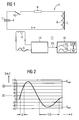
- Fig. 1 the discharge circuit of an electromagnetic Shock wave source 2 in an electrical equivalent circuit diagram by the series connection of a capacitance C, an ohmic Resistor R and an inductance L reproduced.
- the Capacitance C is essentially determined by the capacity of a Charging capacitor 4 determines the one coil 8 connected in parallel is.
- the inductance L of the discharge circuit is essentially determined by the inductance of the Coil 8 (usually a flat coil) and one of these opposite Membrane 6 formed actuator, as he, for example in DE 41 25 375 C1 is described in more detail.
- the ohmic resistance R takes into account both the ohmic resistance the high voltage cable as well as the flat coil. 8 and the induced resistance of the membrane 6.
- the charging capacitor 4 discharged and the discharge current flowing in the discharge circuit I sound up in a muted periodic vibration until the charging capacitor 4 has completely discharged.
- the unloading process is detected with a device 11 and evaluated.
- This measurement signal S is an analog / digital converter 14 supplied and as a digitized measurement signal DS to an evaluation device 16, in the example a Computer, forwarded.
- the digitized measurement signal DS either pointwise with the reference values a stored Reverenzkurve RS compared or alternatively subjected to a previous evaluation, in the one or more characteristics K of the signal waveform of the discharge process reproducing measurement signal DS, for example the period T of the damped oscillation, be determined, then with one to each corresponding stored reference value RK become.
- the deviation of the measuring signals DS or the parameter K from the stored reference signal RS or from the reference value RK is then a measure of the state of wear of the shock wave source Second
- the digitized measurement signal DS used for comparison or the characteristic K are by a moving averaging over several consecutive discharges of free from statistical fluctuations. Because the components of Discharge circuit (charging capacitor, high voltage cable and actual shockwave head (actuator)) Exemplarstreuungen may be at commissioning a new facility or when replacing one of the components on site, a teach-in process carried out.
- the measurement signal DS or the Characteristic K by measuring one or more unloading operations in an initialization or learn mode for that particular one Configuration detected and as a reference signal RS or Reference value RK stored.
- the discharge current I is plotted against the time t.
- the discharge is in the form of a damped oscillation.
- proportional measurement signal S or DS parameters K are determined either by evaluation of the digital data or by direct measurement, which are significant for the discharge process and thus for the state of the shock wave source. These are, for example, the slew rate (I 2 -I 1 ) / ⁇ t, the duration T of the first period and the first and second amplitudes I max and Imin of the current I. These can be used in the evaluation device 16 (FIG stored reference or setpoint values are compared.
- U 0 is the charging voltage of the charging capacitor 4, which is known for each discharge.
- the measurement signal S supplied by the Rogowski coil 12 and applied as voltage U is inverted (-U v ) or not-inverted (U v ) by means of a first operational amplifier 102 and a second operational amplifier 104.
- amplified and low impedance respectively passed to sample-and-hold circuits 106 and 108, respectively. These store the maximum value of the second (minimum U v, min ⁇ Imin of the discharge current) or first half-wave (maximum U v, max ⁇ I max of the discharge current).
- a first comparator 112 with a reference voltage of 0 V detects the zero crossings of the non-inverted amplified measurement signal U v and has its output connected to a sequence control circuit 110. Since experience shows that the first edge of the discharge curve is subject to interference, the second and fourth zero crossing of the curve is used in the exemplary embodiment to determine the period T.
- a second, with its output also connected to the sequence control circuit 110 comparator 114 with a clearly different from 0 reference voltage U T sets the sequence control circuit 110 only then if it takes place with certainty a discharge.
- the period T is determined by a counter 116 whose Start and stop input to control outputs of the sequence control circuit 110 is connected. At the second zero crossing the discharge curve (from positive to negative) becomes the Counter 116 started at the fourth zero crossing (in the same orientation) stopped again. The counter reading is thus a measure of the period T.
- a counter also uses an integrally constructed integrator be used as the voltage value for the measured time duration Provides.
- sample-and-hold circuits 106 and 108 only the maxima in a defined period of time These are determined by the sequence control circuit 110 provided release signals EN1 and EN2 only in this Intervals unlocked. In principle, such is one Activation not required.
- the reset signal R can be derived from the signal "HV-on". This signal "HV-on" is available in an interface to a charging unit with which the charging capacitor is charged. When reset, the storage capacitors of the sample-and-hold circuits 106 and 108 are discharged, the counter 116 and integrator are set to 0, and the process control circuit 110 is set to the initial state.
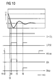
- the sequence control is released. (Charging of the charging capacitor 4 ends, the pulse is imminent) t3 U v > U T
- the sequence control is started.
- This zero crossing stops the counter 116.
- the counter reading is proportional to the period. From now on, no further control signals are output.
- a voltage value is chosen that is significantly greater than the noise in the measurement signal, but certainly less than the expected maximum at the lowest energy level, eg half of the expected maximum at the lowest energy level.
- the value of the inductance L can also be calculated from the initial slope of the measurement signal S ⁇ I.
- the possibly amplified measurement signal U v is for this purpose directly a first sample-and-hold circuit 120 and a high pass 122 of a second sample-and-hold circuit 124 is supplied at the outputs of the maximum current I max and the maximum of the time derivative (dI / dt) max proportional measuring signals are present.
- the capacitance C of the charging capacitor is known and the ohmic resistance of the discharging circuit is assumed to be constant, it is sufficient to measure the maximum current I max during the discharge in order to detect changes in the inductance L.
- the capacitance C of the charging capacitor can be determined from the (known) charging current and the voltage increase during charging.
- FIG. 7 In the alternative embodiment of FIG. 7 is as a transducer a parallel to the charging capacitor 4 switched Voltage divider 40 provided with the charging voltage U via the charging capacitor 4 is detected.
- This will be in the following Facility 11 further processed, as well as in the embodiment of FIG. 1 from an analog / digital converter and a downstream computer can. Also in this case can from the curve of the Measurement signal S either by evaluation of the digital measured values or recorded by direct measurement characteristics, the significant for the unloading process and thus for the State of the shock wave source are.
- a signal processing unit 200 is provided analogously to the exemplary embodiment according to FIG. 3, which at its output provides the period duration T and the first minimum U min of the voltage as characteristics of the signal curve of the voltage U from which are derived in a computer 202 Characteristic variables AK are determined.
- the charging of the charging capacitor 4 takes place with a constant charging current i.
- Voltage U and charging current i are measured.
- the signal from the voltage divider (proportional to the voltage at the charging capacitor) is amplified by means of a first and a second operational amplifier 206 or 208 in an inverted or non-inverted manner and passed on to subsequent processing stages at low impedance.
- the inverted signal is supplied to a sample-and-hold circuit 210. This stores the maximum value U min of the second half-wave (minimum of the voltage).
- the non-inverted signal is output to two comparators 212, 214.
- the first comparator 212 with a reference voltage (U T ) distinctly different from 0 sets the sequence control in motion only when a discharge takes place with certainty.
- the second comparator 214 detects the zero crossings the signal.
- the period T is analogous to Embodiment of FIG. 4 also with a counter 216 determined.
- a counter instead of a counter in This example uses an integrally constructed integrator be used as the voltage value for the measured time duration Provides.
- a scheduler 218 Enable signals enabled only in this interval. In principle, such an activation is also here not mandatory.
- the sequence control circuit 218 After provision of the parameters U min and T, the sequence control circuit 218 remains inactive, ie outputs no further control signals until a reset of the entire evaluation circuit 202 takes place.
- the reset signal is derived from the signal "HV-on". This signal "HV-on" is part of the existing interface to the charger, with which the charging capacitor is charged.
- the storage capacitor of the Sample + Hold circuit 210 When reset, the storage capacitor of the Sample + Hold circuit 210 is discharged, the counter 216 or integrator is set to 0, and the process control circuit 218 is set to the initial state.
- the sequence control is released. (Charging of the charging capacitor finished, the pulse is imminent) t3 U ⁇ U T
- the sequence control is started.
- the S + H circuit 210 is disabled again, the maximum value of this half-wave (proportional to the voltage minimum) is stored.
- t6 U ⁇ 0 This zero crossing stops the counter 216.
- the counter reading is proportional to the period. From now on, no further control signals are output.
Landscapes
- Physics & Mathematics (AREA)
- Engineering & Computer Science (AREA)
- Acoustics & Sound (AREA)
- Multimedia (AREA)
- Mechanical Engineering (AREA)
- Electromagnetism (AREA)
- Testing Relating To Insulation (AREA)
- Measurement Of Resistance Or Impedance (AREA)
Applications Claiming Priority (2)
| Application Number | Priority Date | Filing Date | Title |
|---|---|---|---|
| DE2003149461 DE10349461A1 (de) | 2003-10-23 | 2003-10-23 | Verfahren zum Betreiben einer elektromagnetischen Stoßwellenquelle und nach diesem Verfahren betriebene elektromagnetische Stoßwellenquelle |
| DE10349461 | 2003-10-23 |
Publications (1)
| Publication Number | Publication Date |
|---|---|
| EP1526503A2 true EP1526503A2 (fr) | 2005-04-27 |
Family
ID=34384435
Family Applications (1)
| Application Number | Title | Priority Date | Filing Date |
|---|---|---|---|
| EP20040022727 Withdrawn EP1526503A2 (fr) | 2003-10-23 | 2004-09-23 | Générateur électromagnétique d'ondes de choque et procédé de commande d'un tel générateur |
Country Status (3)
| Country | Link |
|---|---|
| EP (1) | EP1526503A2 (fr) |
| CN (1) | CN1608596A (fr) |
| DE (1) | DE10349461A1 (fr) |
Cited By (1)
| Publication number | Priority date | Publication date | Assignee | Title |
|---|---|---|---|---|
| DE102015002004A1 (de) * | 2015-02-20 | 2016-08-25 | Ali Jasseb | Handyhülle mit Strahlenschutz |
Families Citing this family (3)
| Publication number | Priority date | Publication date | Assignee | Title |
|---|---|---|---|---|
| US7859869B2 (en) | 2008-09-19 | 2010-12-28 | Power Integrations, Inc. | Forward converter transformer saturation prevention |
| US9401634B2 (en) | 2012-10-04 | 2016-07-26 | Power Integrations, Inc. | Saturation prevention in an energy transfer element of a power converter |
| CN103536339B (zh) * | 2013-11-01 | 2015-11-25 | 杜锡鑫 | 体外冲击波碎石机及用于体外冲击波碎石机的充放电电路 |
-
2003
- 2003-10-23 DE DE2003149461 patent/DE10349461A1/de not_active Ceased
-
2004
- 2004-09-23 EP EP20040022727 patent/EP1526503A2/fr not_active Withdrawn
- 2004-10-25 CN CN 200410085924 patent/CN1608596A/zh active Pending
Cited By (1)
| Publication number | Priority date | Publication date | Assignee | Title |
|---|---|---|---|---|
| DE102015002004A1 (de) * | 2015-02-20 | 2016-08-25 | Ali Jasseb | Handyhülle mit Strahlenschutz |
Also Published As
| Publication number | Publication date |
|---|---|
| CN1608596A (zh) | 2005-04-27 |
| DE10349461A1 (de) | 2005-06-02 |
Similar Documents
| Publication | Publication Date | Title |
|---|---|---|
| AT511807B1 (de) | Verfahren und vorrichtung zur online-erkennung einer zustandsverschlechterung einer isolierung in einer elektrischen maschine | |
| EP2347231B1 (fr) | Dispositif détecteur et procédé permettant de faire fonctionner un dispositif détecteur | |
| EP2899563B1 (fr) | Procédé et dispositif de reconnaissance d'une fonction erronée d'un convertisseur à ultrasons par évaluation d'une enveloppante d'impédance | |
| EP0882990A2 (fr) | Procédé et dispositif de détection et de correction d'une forme d'onde de courant saturée d'un transformateur de courant | |
| EP1333256A2 (fr) | Capteur de niveau oscillant | |
| DE10214407C1 (de) | Anordnung und Verfahren zur Messung, Bewertung und Störungserkennung von Systemen | |
| EP1217337A2 (fr) | Méthode pour vérifier le fonctionnement d'un dispositif de mesure du débit | |
| CH657457A5 (de) | Pruefeinrichtung zur bestimmung von schwingungseigenschaften mindestens eines messwertaufnehmers. | |
| DE3813732C2 (fr) | ||
| DE19705430C1 (de) | Verfahren zum Messen des Widerstandes einer an einem Drehübertrager angeschlossenen Last und Anordnung zur Durchführung des Verfahrens | |
| DE102010003624A1 (de) | Verfahren zum Erfassen einer Störung eines Ultraschallwandlers und Störungserfassungsvorrichtung für einen Ultraschallwandler | |
| DE3346387C2 (de) | Schaltungsanordnung zur Erd- oder Körperschlußüberwachung | |
| DE112019000888T5 (de) | System zur Erdung und Diagnose | |
| DE19524499A1 (de) | Zündanlage für eine Brennkraftmaschine | |
| EP1526503A2 (fr) | Générateur électromagnétique d'ondes de choque et procédé de commande d'un tel générateur | |
| EP1098201A2 (fr) | Test de composants passifs | |
| DE69624409T2 (de) | Überwachung der Isolation in elektrischen Fahrzeugen | |
| DE102017128472A1 (de) | Induktiver Näherungsschalter und Verfahren zum Betreiben eines induktiven Näherungsschalters | |
| EP0704825A1 (fr) | Dispositif pour déterminer l'authenticité de pièces de monnaie, de jetons et d'autres objets métalliques plats | |
| DE4001274C2 (fr) | ||
| EP3794361B1 (fr) | Analyse d'état d'un équipement à induction | |
| DE10253864A1 (de) | Verfahren und Anordnung zur Erdschlussüberwachung eines Stators in Sternschaltung | |
| EP4513199B1 (fr) | Commutateur de proximité pour la mesure de la vitesse d'un objet à mesurer | |
| DE102015003227A1 (de) | Verfahren zum Simulieren einer Bordnetz-Welligkeit eines elektrischen Bordnetzes eines Kraftfahrzeugs | |
| EP3446134B1 (fr) | Détermination de la mise en contact électrique d'un système électrique avec un système de mesure |
Legal Events
| Date | Code | Title | Description |
|---|---|---|---|
| PUAI | Public reference made under article 153(3) epc to a published international application that has entered the european phase |
Free format text: ORIGINAL CODE: 0009012 |
|
| AK | Designated contracting states |
Kind code of ref document: A2 Designated state(s): AT BE BG CH CY CZ DE DK EE ES FI FR GB GR HU IE IT LI LU MC NL PL PT RO SE SI SK TR |
|
| AX | Request for extension of the european patent |
Extension state: AL HR LT LV MK |
|
| STAA | Information on the status of an ep patent application or granted ep patent |
Free format text: STATUS: THE APPLICATION IS DEEMED TO BE WITHDRAWN |
|
| 18D | Application deemed to be withdrawn |
Effective date: 20090401 |