EP1526766B1 - Semoir - Google Patents
Semoir Download PDFInfo
- Publication number
- EP1526766B1 EP1526766B1 EP03792162A EP03792162A EP1526766B1 EP 1526766 B1 EP1526766 B1 EP 1526766B1 EP 03792162 A EP03792162 A EP 03792162A EP 03792162 A EP03792162 A EP 03792162A EP 1526766 B1 EP1526766 B1 EP 1526766B1
- Authority
- EP
- European Patent Office
- Prior art keywords
- product
- air
- nozzle assembly
- machine according
- seeding machine
- Prior art date
- Legal status (The legal status is an assumption and is not a legal conclusion. Google has not performed a legal analysis and makes no representation as to the accuracy of the status listed.)
- Expired - Lifetime
Links
- 238000010899 nucleation Methods 0.000 title claims 21
- 238000011144 upstream manufacturing Methods 0.000 claims description 9
- 238000004140 cleaning Methods 0.000 description 10
- 238000009825 accumulation Methods 0.000 description 7
- 241000196324 Embryophyta Species 0.000 description 4
- 239000002245 particle Substances 0.000 description 3
- 238000009331 sowing Methods 0.000 description 3
- 238000009423 ventilation Methods 0.000 description 3
- 244000068988 Glycine max Species 0.000 description 2
- 235000010469 Glycine max Nutrition 0.000 description 2
- 240000008042 Zea mays Species 0.000 description 2
- 235000005824 Zea mays ssp. parviglumis Nutrition 0.000 description 2
- 235000002017 Zea mays subsp mays Nutrition 0.000 description 2
- 230000000712 assembly Effects 0.000 description 2
- 238000000429 assembly Methods 0.000 description 2
- 235000005822 corn Nutrition 0.000 description 2
- 238000007599 discharging Methods 0.000 description 2
- 230000005484 gravity Effects 0.000 description 2
- 239000000463 material Substances 0.000 description 2
- 230000002238 attenuated effect Effects 0.000 description 1
- 230000001419 dependent effect Effects 0.000 description 1
- 238000011161 development Methods 0.000 description 1
- 230000018109 developmental process Effects 0.000 description 1
- 239000003337 fertilizer Substances 0.000 description 1
- 229920001821 foam rubber Polymers 0.000 description 1
- 238000004519 manufacturing process Methods 0.000 description 1
- 238000012986 modification Methods 0.000 description 1
- 230000004048 modification Effects 0.000 description 1
- 239000000575 pesticide Substances 0.000 description 1
- 238000007789 sealing Methods 0.000 description 1
- 238000003756 stirring Methods 0.000 description 1
- 239000000126 substance Substances 0.000 description 1
- 239000000725 suspension Substances 0.000 description 1
Images




Classifications
-
- A—HUMAN NECESSITIES
- A01—AGRICULTURE; FORESTRY; ANIMAL HUSBANDRY; HUNTING; TRAPPING; FISHING
- A01C—PLANTING; SOWING; FERTILISING
- A01C7/00—Sowing
- A01C7/08—Broadcast seeders; Seeders depositing seeds in rows
- A01C7/081—Seeders depositing seeds in rows using pneumatic means
-
- A—HUMAN NECESSITIES
- A01—AGRICULTURE; FORESTRY; ANIMAL HUSBANDRY; HUNTING; TRAPPING; FISHING
- A01C—PLANTING; SOWING; FERTILISING
- A01C15/00—Fertiliser distributors
- A01C15/04—Fertiliser distributors using blowers
Definitions
- the invention relates to a sowing machine for an agricultural product.
- the drill includes a main reservoir containing a nozzle assembly into which the product contained in the main reservoir is directed, the nozzle assembly having an upstream side wall and a downstream side wall.
- the drill includes a plurality of application units having a product metering device and an applicator for discharging the product onto the field, each product metering device being connected to the downstream side sidewall of the nozzle assembly via a product supply line.
- the seeder includes an air pump pneumatically connected to the upstream side walls of the nozzle assembly through a plurality of air supply lines, the air pump generating compressed air that is directed into the air supply lines.
- the number of air supply lines corresponds to the number of application units.
- Each air supply line includes an air inlet port connected to the nozzle assembly, opposite the product output port product outlet.
- the product in the nozzle assembly is received by the airflow as the airflow from the air inlet passage of the corresponding air supply conduit through the nozzle assembly flows into the corresponding product delivery conduit product outlet conduit, the product delivery conduit directing the product to the corresponding product metering device.
- Pneumatic on-demand product delivery systems are used in agricultural seed drills for the automatic transport of seeds from a main container to several individual plant units.
- Each of the individual plant units contains a seed hopper for receiving seeds, a seed metering device for metering the seed from the seed hopper, and a furrow opener for forming a planting furrow into which the metered seed is deposited.
- a blower is used to generate compressed air. The compressed air generates an airflow through which the seed is transported into the planting units.
- Air powered seeders dose seed upstream from the transporting airflow. Because the dosing device is far away from the dispensing device, the seed deposited on the field is not dosed as accurately as when the dosing device is positioned in the immediate vicinity of the dispensing device.
- the commercially available seeders usually require a large blower to generate the air flow.
- the great. Blower is required because of the pressure losses within the pneumatic system caused by abrupt changes of direction of the air flow in the main tank.
- Such a machine is disclosed, for example, in US 5 161 473 A.
- a main container compressed air By interacting with a main container compressed air, a re-suspension of seed is achieved, which is conveyed by the vortex movement in a seed supply: This requires a high level of compressed air production.
- Turbulence in the seed caused blockages in the seed supply line and / or in the air supply line.
- a different seed drill is disclosed in FR 2 591 416 A.
- seed is conveyed out of a seed main container by means of compressed air, by means of funnel-shaped nozzle arrangements, the seed is passed directly into an applied with the air flow Saatgutzuschreibtechnisch.
- the disadvantage is that the seed falls directly into the seed supply line and can clog it up. Furthermore, a high degree of compressed air generation is also necessary here.
- the object underlying the invention is seen to provide a sowing machine of the type mentioned, by which the aforementioned problems are overcome.
- a seed drill of the type mentioned in the introduction comprises a nozzle arrangement which is provided with a number of diaphragms corresponding to the number of application units, the diaphragms extending between and above the air inlet ducts of the air supply ducts and the corresponding product outlet ducts of the product supply ducts. Because of that Air inlet ducts of the air supply lines are arranged opposite to the product outlet ducts of the product supply lines, the air flow flowing through the main container is not exposed to abrupt changes of direction. This pressure losses can be minimized.
- the adjacent combinations of air inlet duct and product outlet duct are spaced transversely of each other such that seed or non-seed can pass both sides of the panels and accumulate under the panels. A flowing through the air inlet channel in the Gutausgangskanal air stream absorbs good from the accumulation.
- the air pump generates the compressed air needed to carry the product, which is fed to the air supply lines.
- the air supply ducts are connected to air intake ducts formed at the bottom of the main tank. Compared to the air inlet channels corresponding product output channels are formed, which receive the air flow with the recorded by the air flow product.
- the product output channels are connected to product supply lines.
- the product supply lines are again with connected to the dispensing units containing auxiliary containers.
- the nozzle arrangement is equipped with a plurality of apertures, wherein the number of apertures corresponds to the number of dispensing units.
- the orifices extend between and above the air inlet ducts of the air supply ducts and the corresponding product output ducts of the product supply ducts.
- the air inlet channels and the product outlet channels are arranged such that the air flow flows from the air supply line below the baffles.
- the apertures disposed above the air inlet passages and product exit passages are preferably tapered upwardly so that the product falls to the bottom of the nozzle assembly and accumulates under the nozzle assembly. Furthermore, free spaces are formed between the adjacent orifices, such that the product in the main container passes by gravity into the nozzle arrangement and the product from the main container can flow into the product accumulation or product accumulation.
- the product outlet channels of the product supply lines are arranged upwardly relative to the bottom of the nozzle arrangement. Furthermore, the air inlet ducts of the air supply ducts are relative to the bottom of the nozzle assembly arranged downwards. Further, the bottom of the nozzle assembly is concave-shaped and the upstream and downstream side walls divide outwardly.
- an air flow distributor is included, which is pneumatically connected to the air pump upstream of the air supply line, wherein each of the air supply lines is pneumatically connected to the air flow distributor.
- the air flow distributor is formed by a hollow portion of the main container supporting frame and thus the variety of parts of the drill kept small. The compressed air conveyed by the air pump passes through the air flow distributor in equal proportions to the individual air supply lines and thus in equal parts via the air inlet channels in the nozzle assemblies. This achieves even product distribution across the product output ports into each product supply line.
- the nozzle arrangement is provided with a cleaning flap, which is arranged below the air inlet ducts of the air supply lines and the product outlet channels of the product supply lines.
- Each application unit preferably includes a planting unit having a product metering device containing a seed metering device and a discharge device containing a furrow opener.
- the inventive Sowing machine can thus be used for demand-based delivery of seed from a main container to a seed hopper located on the planting unit.
- the planting unit may contain an auxiliary container which feeds or supplies a seed metering device with seed.
- the seed metering device in turn delivers seed in metered form via a furrow opener into a planting furrow.
- the seed metering devices can be designed as a vacuum seed metering device.
- the air inlet ducts of the air supply ducts are provided with inserts which include an air flow deflecting member which deflects a portion of the air flow downwardly toward the bottom of the nozzle assembly to agitate the product located on the bottom of the nozzle assembly.
- inserts which include an air flow deflecting member which deflects a portion of the air flow downwardly toward the bottom of the nozzle assembly to agitate the product located on the bottom of the nozzle assembly.
- the product has larger particles, such.
- such an insert can be used in the air inlet channel, so that the deflected down part of the air flow meets the product accumulation and these so swirled that the uptake of the product is facilitated by the flowing into the product outlet channel air flow.
- the baffles are provided with an element which includes a delimiting bottom to limit the amount of product exposed to the airflow passing between the air inlet ducts of the air supply ducts and the product outlet ducts of the product supply ducts.
- the nozzle assembly can then be provided with a plug-on element which is attached to the diaphragms and limits the air flow acting on the product accumulation by covering a part of the product accumulation.
- the nozzle assembly is provided with an agitator device which includes a transverse rod extending transversely of the nozzle assembly and provided with a plurality of radially extending fingers.
- the crossbar rotates alternately back and forth over an angle of preferably 180 degrees and is driven by a geared motor assembly.
- the radially extending fingers pass through the free spaces between the individual panels and loosen or stir the product.
- An agricultural seeder 10 includes a frame 12 on which a plurality of individual planting units 14 are mounted.
- the planting units 14 are connected to the frame 12 via a parallelogram linkage 16 so that the individual planting units 14 can move up and down relative to the frame 12 to a limited extent.
- Each of the individual plant units 14 includes a seed hopper 18 for receiving seed, a seed metering device 20 for metering the seed received from the seed hopper 18, and a furrow opener 22 for forming a seed furrow on a field for receiving the seed metered by the seed metering device 20.
- the seed is passed through a seed tube 24 from the seed metering device 20 into the planting furrow.
- a closing device 26 is used to close the seed furrow containing Graphfurche.
- the seed metering device 20 is a vacuum seed metering device, although other types of seed metering devices using mechanical assemblies or overpressure could also be used. It should be noted that the invention could also be used to deploy non-seed on the field.
- the planting unit 14 may be considered as an application unit having an auxiliary container for receiving a crop, a metering device for metering the crop received by the auxiliary container, and a discharge device for discharging the metered crop onto the field become.
- a chemical dry fertilizer or pesticides could be directed into the auxiliary container, metered through the metering device, and applied to the field by the dispenser.
- the main frame 12 carries a main tank 30 and a compressed air pump 32.
- the compressed air pump 32 is driven by a hydraulic motor, whereby other engine arrangements, such. B. electric motors for driving the air pump 32 could be used.
- the air pump 32 delivers pressurized air through a main air hose 36 into a manifold 34.
- the manifold 34 is formed from a hollow closed tubular support of the frame 12.
- the distributor 34 is provided with a plurality of distributor outlet openings corresponding to the number of plant units 14 containing the frame 12.
- Individual air supply lines 38 extend from the manifold outlet ports and direct compressed air from the manifold 34 into the flow input side of the nozzle assembly 39.
- the nozzle assembly 39 is disposed on the bottom of the main reservoir 30.
- the nozzle assembly 39 is provided with a number of air inlet channels 41, which corresponds to the number of air supply lines 38.
- the air inlet passages 41 are arranged at a distance from each other transversely along the flow inlet side.
- the flow exit side of the nozzle assembly 39 is provided with a number of good exit ports 43 corresponding to the number of air supply conduits 38.
- the Gutausgangskanäle 43 are also arranged transversely spaced along the flow exit side of the nozzle assembly 39 to each other.
- the Gutausgangskanäle 43 are opposite the air inlet channels 41.
- Each air inlet channel 41 is aligned with a corresponding good output channel 43 aligned.
- Good supply hoses 42 extend from the Gutausgangskanälen 43 to the individual auxiliary containers 18 and direct the air entrained Good to the auxiliary containers 18th
- the nozzle assembly 39 is formed with a concave bottom 44 containing outwardly diverging sidewalls 45, 46.
- the crop in the form of seed or non-seed is introduced into the main container 30 through a lid 47.
- Portions of the nozzle assembly 39 may be opened to provide a cleaning port 48.
- the cleaning port 48 is pivotally connected to the nozzle assembly 39 by a hinge pin 50.
- the cleaning port is locked by a latch 52 which communicates with the inner side walls 45, 46 of the main tank 30.
- the latch 52 is pivoted 90 ° so that the legs of the latch 52 are no longer in contact with the inner side walls 45, 46.
- the cleaning flap 48 is then pivoted over the hinge pin 50 so that it hangs below the hinge pin 50.
- an elastic rubber foam seal 56 is arranged between the cleaning flap 48 and the outer surface of the outwardly diverging side walls 45, 46, for sealing the main container 30 with the cleaning flap 48 closed.
- Each air inlet channel 41 and associated Gutausgangskanal 43 is formed of two plastic parts.
- the two plastic parts are assembled by means of built-in plugs, which are formed on one part, and receiving openings, which are formed on the other part.
- the air inlet channel 41 is disposed inclined downward relative to the concave bottom 44 and the Gutausgangskanal 43 is correspondingly arranged relative to the concave bottom 44 inclined upward.
- Between the air inlet channel 41 and the Gutausgangskanal 43 extends a built-in aperture 58.
- the aperture 58 is tapered and is above the air flow passing through the air inlet channel 41 and the Gutausgangskanal 43, respectively.
- the downwardly sloping air intake passage 41 prevents goods from returning to the air supply line 38, whereas the upwardly directed good exit passage 43 prevents goods from flowing into and clogging the good supply hose 42.
- the adjacent combinations of air inlet channel 41 and gut exit channel 43 are arranged transversely spaced from each other, so that seed or non-seed on both sides of the aperture 58 pass over and can accumulate under the aperture 58.
- a flowing through the air inlet channel 41 into the Gutausgangskanal 43 air stream takes on good from the accumulation and promotes it through the Gutmakerssschlauch 42 in the seed aid 18.
- the promotion of good from the main tank 30 in the seed aid 18 is done automatically as soon as good in the Saatgutos maiern 18 needed becomes.
- the Guteinlasskanal 60 of the Saatgutins meansers 18 is exposed when the good through the Seed metering device 20 has been used up, so that the air flow again receives good for promotion in the seed auxiliary container 18.
- the seed auxiliary containers 18 are always and automatically supplied with goods.
- the side walls of the seed auxiliary containers 18 are provided with ventilation openings 61 for reducing the air pressure in the seed auxiliary container 18.
- the ventilation openings 61 may also be arranged on the cover of the seed auxiliary containers 18 as long as the ventilation openings 61 are located above the corresponding good inlet channels 60.
- the air inlet channel 41 may be provided with an insert 62 which includes an airflow diverting portion 64 through which a portion of the airflow is deflected downward to spin up the seeds in the cluster such that the seeds extend from the ground into the Gutausgangskanal 43 flowing air flow to be captured.
- the insert 62 is provided with a passport 66 which engages a notch formed in the air inlet passage 41 to ensure correct positioning of the insert 62 and the airflow deflecting member.
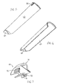
- the shutters 58 may be provided with a clip member 68 (product receiving limit member).
- the clip member 68 may be attached to the bezel 58.
- the clip member 68 includes a delimiting floor 70 with which the amount of material exposed to the air flow is limited.
- the clip element 68 is made of plastic and provided with clamping handles 72. By compressing the clamping handles 72, an upper gap 74 is opened, so that the clip member 68 can be attached to the aperture 58.
- the insert 62 provided for the large seeds may be replaced by an agitator assembly 80.
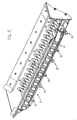
- the agitator assembly 80 includes a cross bar 82 that extends across the nozzle assembly 39.
- the crossbar 82 is provided with a plurality of radially extending fingers 84. As shown in Fig. 10, the fingers are transversely aligned with each other.
- the crossbar 82 is rotated back and forth by a gear 86 driven by a motor 88.
- the fingers 84 extend between the individual nozzles, which are formed by the mutually aligned air inlet channels 41 and good exit channels 43. In this way, the fingers 84 sweep the area between the nozzles.
- the gear / motor assembly 86, 88 twists the crossbar 82 fifty-one and a half degrees in either direction from bottom dead center position as shown in FIG. This causes the fingers to go through an angle of one hundred and three degrees.
Landscapes
- Life Sciences & Earth Sciences (AREA)
- Soil Sciences (AREA)
- Environmental Sciences (AREA)
- Sowing (AREA)
- Pretreatment Of Seeds And Plants (AREA)
- Feeding Of Articles To Conveyors (AREA)
Claims (20)
- Semoir, comportant- une trémie principale (30), qui comporte un système de buses (39), dans lequel est acheminé le produit contenu dans la trémie principale (30), le système de buses (39) comportant une paroi latérale (45) du côté amont et une paroi latérale (46) du côté aval du fllux,- plusieurs unités de distribution (14) munies d'un dispositif de dosage du produit (20) et d'un dispositif de distribution destiné à distribuer le produit sur le champ, chaque dispositif de dosage du produit (20) étant relié via une conduite d'alimentation en produit (42) avec la paroi latérale du côté aval (46) du système de buses (39),- une pompe à air (32) reliée par voie pneumatique, via plusieurs conduites d'admission d'air (38), à la paroi latérale du côté amont (45) du système de buses (39),la pompe à air (32) générant de l'air comprimé, qui est acheminé dans les conduites d'admission d'air (38), le nombre de conduites d'admission d'air (38) correspondant au nombre d'unités de distribution (14) et chaque conduite d'admission d'air (38) contenant un canal d'entrée d'air (41), qui est relié au système de buses (39) et qui est situé en regard du canal de sortie du produit (43) de la conduite d'alimentation en produit (42), de telle sorte que le produit contenu dans le système de buses (39) est reçu par le flux d'air lorsque le flux d'air afflue hors du canal d'entrée d'air (41) de la conduite d'admission d'air (38) correspondante à travers le système de buses (39) dans le canal de sortie de produit (43) de la conduite d'alimentation en produit (42) et la conduite d'alimentation en produit (42) achemine le produit vers le dispositif de dosage du produit (20) correspondant, caractérisé en ce que le système de buses (39) est muni d'obturateurs (58) dont le nombre correspond au nombre d'unités de distribution (14), les obturateurs (58) étant disposés entre et au-dessus des canaux d'entrée d'air (41) des conduites d'admission d'air (38) et des canaux de sortie de produit (43) des conduites d'alimentation en produit (42).
- Semoir selon l'une quelconque des revendications précédentes, caractérisé en ce que le flux d'air sortant de la conduite d'admission d'air (38) circule en dessous des obturateurs (58).
- Semoir selon l'une quelconque des revendications précédentes, caractérisé en ce que chaque obturateur (58) est réalisé en se terminant en pointe vers le haut, des espaces libres étant formés entre des obturateurs (58) voisins, de telle sorte que le produit tombe sur un fond (44) du système de buses (39).
- Semoir selon l'une quelconque des revendications précédentes, caractérisé en ce que les canaux de sortie de produit (43) des conduites d'alimentation en produit (42) sont orientés vers le haut par rapport au fond (44) du système de buses (39).
- Semoir selon l'une quelconque des revendications précédentes, caractérisé en ce que les canaux d'entrée d'air (41) des conduites d'admission d'air (38) sont orientés vers le bas par rapport au fond (44) du système de buses (39).
- Semoir selon l'une quelconque des revendications précédentes, caractérisé en ce que le fond (44) du système de buses (39) a une forme concave et les parois latérales (45, 46) du côté amont et du côté aval, s'étendent vers l'extérieur en s'écartant l'une de l'autre.
- Semoir selon l'une quelconque des revendications précédentes, caractérisé en ce que chaque unité de distribution (14) est munie d'un réservoir auxiliaire (18) positionné entre le canal d'entrée de produit (60) et le dispositif de dosage de produit (20).
- Semoir selon l'une quelconque des revendications précédentes, caractérisé en ce qu'il comporte un répartiteur d'air (34), qui est relié en amont, par voie pneumatique via la conduite d'admission d'air (38), à la pompe à air (32), chacune des conduites d'admission d'air (38) étant reliées par voie pneumatique au répartiteur d'air (34).
- Semoir selon la revendication 8, caractérisé en ce que le répartiteur d'air (34) est formé par une partie creuse d'un bâti (12) portant la trémie principale (30).
- Semoir selon l'une quelconque des revendications précédentes, caractérisé en ce que le système de buses (39) comporte une vanne de nettoyage (48) qui est agencée en dessous des canaux d'entrée d'air (41) des conduites d'admission d'air (38) et des canaux de sortie de produit (43) des conduites d'alimentation en produit (42).
- Semoir selon l'une quelconque des revendications précédentes, caractérisé en ce que les canaux d'entrée d'air (41) des conduites d'admission d'air (38) comportent des inserts (62) qui sont munis d'un déflecteur (64), par lequel une partie du flux d'air est déviée vers le bas en direction du fond (44) du système de buses (39) afin de faire tourbillonner le produit disposé sur le fond (44) du système de buses (39).
- Semoir selon l'une quelconque des revendications précédentes, caractérisé en ce que les obturateurs (58) sont munis d'un élément (68), qui comporte un fond (70) restrictif en vue de limiter les quantités de produit exposées au flux d'air circulant entre les canaux d'entrée d'air (41) des conduites d'admission d'air (38) et les canaux de sortie de produit (43) des conduites d'alimentation en produit (42).
- Semoir selon la revendication 12, caractérisé en ce que l'élément (68) est un élément enfichable sous la forme d'un élément à encliquetage.
- Semoir selon l'une quelconque des revendications précédentes, caractérisé en ce qu'un mécanisme de brassage (80) est monté dans le système de buses (39) afin de brasser le produit contenu dans le système de buses (39).
- Semoir selon la revendication 14, caractérisé en ce que le mécanisme de brassage (80) comporte plusieurs doigts (84), qui s'étendent dans les espaces libres formés entres les obturateurs (58) voisins.
- Semoir selon la revendication 14 ou 15, caractérisé en ce que le mécanisme de brassage (80) comporte une barre transversale (82), agencée au-dessus des obturateurs (58), la barre transversale (82) comportant plusieurs doigts (84), qui s'étendent radialement vers l'extérieur à partir de la barre (82) orientée transversalement.
- Semoir selon la revendication 15 ou 16, caractérisé en ce que les doigts (84) sur la barre (82) transversale sont orientés dans le sens transversal les uns par rapport aux autres.
- Semoir selon l'une quelconque des revendications 15 à 17, caractérisé en ce que la barre transversale (82) peut tourner en va-et-vient, de telle sorte que les doigts (84) brassent le produit contenu dans le système de buses (39).
- Semoir selon l'une quelconque des revendications 14 à 18, caractérisé en ce que la barre transversale (82) peut tourner en va-et-vient en suivant un arc de cercle de 103 degrés.
- Semoir selon la revendication 19, caractérisé en ce que le centre de l'arc de cercle couvrant un angle de 103 degrés représente la position de point mort inférieur par rapport au système de buses (39).
Applications Claiming Priority (5)
| Application Number | Priority Date | Filing Date | Title |
|---|---|---|---|
| US214970 | 1988-07-05 | ||
| US214957 | 2002-08-08 | ||
| US10/214,970 US6609468B1 (en) | 2002-08-08 | 2002-08-08 | Product on demand delivery system having an agitator assembly |
| US10/214,957 US6688244B1 (en) | 2002-08-08 | 2002-08-08 | Product on demand delivery system |
| PCT/EP2003/006675 WO2004017712A1 (fr) | 2002-08-08 | 2003-06-25 | Semoir |
Publications (2)
| Publication Number | Publication Date |
|---|---|
| EP1526766A1 EP1526766A1 (fr) | 2005-05-04 |
| EP1526766B1 true EP1526766B1 (fr) | 2006-05-03 |
Family
ID=31949770
Family Applications (1)
| Application Number | Title | Priority Date | Filing Date |
|---|---|---|---|
| EP03792162A Expired - Lifetime EP1526766B1 (fr) | 2002-08-08 | 2003-06-25 | Semoir |
Country Status (8)
| Country | Link |
|---|---|
| EP (1) | EP1526766B1 (fr) |
| AU (1) | AU2003249870A1 (fr) |
| DE (1) | DE50303220D1 (fr) |
| ES (1) | ES2259154T3 (fr) |
| PL (1) | PL214280B1 (fr) |
| RU (1) | RU2314668C2 (fr) |
| UA (1) | UA80434C2 (fr) |
| WO (1) | WO2004017712A1 (fr) |
Families Citing this family (14)
| Publication number | Priority date | Publication date | Assignee | Title |
|---|---|---|---|---|
| CA2977467C (fr) | 2016-10-11 | 2026-01-13 | Deere & Company | Mecanisme de semoir |
| US10942053B2 (en) | 2018-05-14 | 2021-03-09 | Deere & Company | Seeding system |
| US11490558B2 (en) | 2019-12-24 | 2022-11-08 | Cnh Industrial America Llc | Particle delivery system of an agricultural row unit |
| US11553639B2 (en) | 2019-12-24 | 2023-01-17 | Cnh Industrial America Llc | Particle delivery system of an agricultural row unit |
| US11589500B2 (en) | 2019-12-24 | 2023-02-28 | Cnh Industrial America Llc | Particle delivery system of an agricultural row unit |
| US11582899B2 (en) | 2019-12-24 | 2023-02-21 | Cnh Industrial America Llc | Particle delivery system of an agricultural row unit |
| US11564346B2 (en) | 2019-12-24 | 2023-01-31 | Cnh Industrial America Llc | Particle delivery system of an agricultural row unit |
| US11523556B2 (en) | 2019-12-24 | 2022-12-13 | Cnh Industrial America Llc | Particle delivery system of an agricultural row unit |
| US11523555B2 (en) | 2019-12-24 | 2022-12-13 | Cnh Industrial America Llc | Particle delivery system of an agricultural row unit |
| US11483963B2 (en) | 2019-12-24 | 2022-11-01 | Cnh Industrial America Llc | Particle delivery system of an agricultural row unit |
| US11564344B2 (en) | 2019-12-24 | 2023-01-31 | Cnh Industrial America Llc | Particle delivery system of an agricultural row unit |
| US11516958B2 (en) | 2019-12-24 | 2022-12-06 | Cnh Industrial America Llc | Particle delivery system of an agricultural row unit |
| US11596095B2 (en) | 2019-12-24 | 2023-03-07 | Cnh Industrial America Llc | Particle delivery system of an agricultural row unit |
| US11553638B2 (en) | 2019-12-24 | 2023-01-17 | Cnh Industrial America Llc | Particle delivery system of an agricultural row unit |
Family Cites Families (8)
| Publication number | Priority date | Publication date | Assignee | Title |
|---|---|---|---|---|
| GB593983A (en) * | 1945-06-21 | 1947-10-30 | Wallace James Parker | Improvements in or relating to devices for sowing seeds |
| US3804036A (en) * | 1972-10-05 | 1974-04-16 | E Seifert | Air induction apparatus for seed drill tube |
| US4296695A (en) * | 1978-04-03 | 1981-10-27 | Wil-Rich, Inc. | Seeding device with air distribution system |
| US4503786A (en) * | 1980-12-24 | 1985-03-12 | Tautfest Rexford L | Grain drill with sealed bin air-powered distribution |
| US4514114A (en) * | 1982-07-08 | 1985-04-30 | Fuss Albert K | Seed and/or fertilizer distributor |
| IT1182626B (it) * | 1985-10-18 | 1987-10-05 | Mec Off | Seminatrice pneumatica trasformabile in spandiconcime |
| US4705220A (en) * | 1985-11-25 | 1987-11-10 | Gandy Company | Granular applicator with interchangeable metering wheels |
| US5161473A (en) * | 1991-05-17 | 1992-11-10 | Deere & Company | Seed distribution system and method for a seeding implement |
-
2003
- 2003-06-25 PL PL374105A patent/PL214280B1/pl unknown
- 2003-06-25 AU AU2003249870A patent/AU2003249870A1/en not_active Abandoned
- 2003-06-25 WO PCT/EP2003/006675 patent/WO2004017712A1/fr not_active Ceased
- 2003-06-25 ES ES03792162T patent/ES2259154T3/es not_active Expired - Lifetime
- 2003-06-25 DE DE50303220T patent/DE50303220D1/de not_active Expired - Lifetime
- 2003-06-25 EP EP03792162A patent/EP1526766B1/fr not_active Expired - Lifetime
- 2003-06-25 RU RU2005106290/12A patent/RU2314668C2/ru not_active IP Right Cessation
- 2003-06-25 UA UAA200501227A patent/UA80434C2/uk unknown
Also Published As
| Publication number | Publication date |
|---|---|
| WO2004017712A1 (fr) | 2004-03-04 |
| RU2005106290A (ru) | 2006-01-20 |
| EP1526766A1 (fr) | 2005-05-04 |
| DE50303220D1 (de) | 2006-06-08 |
| ES2259154T3 (es) | 2006-09-16 |
| AU2003249870A1 (en) | 2004-03-11 |
| PL214280B1 (pl) | 2013-07-31 |
| RU2314668C2 (ru) | 2008-01-20 |
| PL374105A1 (en) | 2005-09-19 |
| UA80434C2 (uk) | 2007-09-25 |
Similar Documents
| Publication | Publication Date | Title |
|---|---|---|
| EP1591000B1 (fr) | Système de delivrance pour produits agricoles | |
| US7213525B2 (en) | Nozzle assembly for product-on-demand delivery system | |
| EP1526766B1 (fr) | Semoir | |
| DE69623295T2 (de) | Saat-messmethode und vorrichtung | |
| US6688244B1 (en) | Product on demand delivery system | |
| EP1593295B1 (fr) | Système de distribution pour un produit agricole | |
| US7025010B2 (en) | Flow splitter arrangement for series fed product application units | |
| DE69921936T2 (de) | Induktorgerät für Behälter in pneumatischen Drillmaschinen | |
| DE102019201393A1 (de) | Reiheneinheit für eine Sämaschine mit pneumatischem Fördersystem | |
| US6609468B1 (en) | Product on demand delivery system having an agitator assembly | |
| EP1428420B1 (fr) | Système doseur d'un semoir | |
| EP1003359A1 (fr) | Systeme de distribution d'un dispositif d'ensemencement | |
| EP0799560A2 (fr) | Conduite pour l'air de sortie d'un distributeur pneumatique | |
| DE2629278A1 (de) | Verfahren und vorrichtung zur streugutzufuhrregulierung an mit druckluft betriebenen streugutverteil- und dosiermaschinen, insbesondere saemaschinen | |
| DE102019201399A1 (de) | Reiheneinheit für eine sämaschine mit pneumatischer saatgutbeladung | |
| EP1504642B1 (fr) | Semoir | |
| EP4199691B1 (fr) | Dispositif de sélection de graines comportant un système de séparation et semoir équipé dudit dispositif de sélection de graines | |
| EP4000364A1 (fr) | Tête d'épandage pour une machine à semer et/ou à épandre du fumier | |
| DE19549577C3 (de) | Landwirtschaftliche Verteilmaschine | |
| DE60302421T2 (de) | Dosiervorrichtung für eine Sämaschine | |
| EP3945767B1 (fr) | Dispositif de distribution pour matière granulée | |
| DE2241534C3 (de) | Dosiergerät für pneumatisch arbeitende Verteilersysteme | |
| EP3917304B1 (fr) | Sas d'introduction de matière pour un épandeur et épandeur | |
| DE102022105720B3 (de) | Verteilerkopf für eine landwirtschaftliche Ausbringmaschine und Ausbringmaschine zum Verteilen von Material | |
| DE3515362A1 (de) | Vorrichtung zum streuen von schuettfaehigem gut, insbesondere duenger |
Legal Events
| Date | Code | Title | Description |
|---|---|---|---|
| PUAI | Public reference made under article 153(3) epc to a published international application that has entered the european phase |
Free format text: ORIGINAL CODE: 0009012 |
|
| 17P | Request for examination filed |
Effective date: 20041117 |
|
| AK | Designated contracting states |
Kind code of ref document: A1 Designated state(s): AT BE BG CH CY CZ DE DK EE ES FI FR GB GR HU IE IT LI LU MC NL PT RO SE SI SK TR |
|
| AX | Request for extension of the european patent |
Extension state: AL LT LV MK |
|
| GRAP | Despatch of communication of intention to grant a patent |
Free format text: ORIGINAL CODE: EPIDOSNIGR1 |
|
| DAX | Request for extension of the european patent (deleted) | ||
| RBV | Designated contracting states (corrected) |
Designated state(s): DE ES FR HU IT |
|
| GRAS | Grant fee paid |
Free format text: ORIGINAL CODE: EPIDOSNIGR3 |
|
| GRAA | (expected) grant |
Free format text: ORIGINAL CODE: 0009210 |
|
| AK | Designated contracting states |
Kind code of ref document: B1 Designated state(s): DE ES FR HU IT |
|
| REF | Corresponds to: |
Ref document number: 50303220 Country of ref document: DE Date of ref document: 20060608 Kind code of ref document: P |
|
| REG | Reference to a national code |
Ref country code: ES Ref legal event code: FG2A Ref document number: 2259154 Country of ref document: ES Kind code of ref document: T3 |
|
| REG | Reference to a national code |
Ref country code: HU Ref legal event code: AG4A Ref document number: E000529 Country of ref document: HU |
|
| ET | Fr: translation filed | ||
| PLBE | No opposition filed within time limit |
Free format text: ORIGINAL CODE: 0009261 |
|
| STAA | Information on the status of an ep patent application or granted ep patent |
Free format text: STATUS: NO OPPOSITION FILED WITHIN TIME LIMIT |
|
| 26N | No opposition filed |
Effective date: 20070206 |
|
| PGFP | Annual fee paid to national office [announced via postgrant information from national office to epo] |
Ref country code: ES Payment date: 20140626 Year of fee payment: 12 Ref country code: IT Payment date: 20140624 Year of fee payment: 12 |
|
| PGFP | Annual fee paid to national office [announced via postgrant information from national office to epo] |
Ref country code: HU Payment date: 20140606 Year of fee payment: 12 |
|
| PG25 | Lapsed in a contracting state [announced via postgrant information from national office to epo] |
Ref country code: IT Free format text: LAPSE BECAUSE OF NON-PAYMENT OF DUE FEES Effective date: 20150625 |
|
| PG25 | Lapsed in a contracting state [announced via postgrant information from national office to epo] |
Ref country code: HU Free format text: LAPSE BECAUSE OF NON-PAYMENT OF DUE FEES Effective date: 20150626 |
|
| REG | Reference to a national code |
Ref country code: FR Ref legal event code: PLFP Year of fee payment: 14 |
|
| REG | Reference to a national code |
Ref country code: FR Ref legal event code: PLFP Year of fee payment: 15 |
|
| PG25 | Lapsed in a contracting state [announced via postgrant information from national office to epo] |
Ref country code: ES Free format text: LAPSE BECAUSE OF NON-PAYMENT OF DUE FEES Effective date: 20150626 |
|
| REG | Reference to a national code |
Ref country code: FR Ref legal event code: PLFP Year of fee payment: 16 |
|
| REG | Reference to a national code |
Ref country code: ES Ref legal event code: FD2A Effective date: 20180704 |
|
| PGFP | Annual fee paid to national office [announced via postgrant information from national office to epo] |
Ref country code: DE Payment date: 20220519 Year of fee payment: 20 |
|
| PGFP | Annual fee paid to national office [announced via postgrant information from national office to epo] |
Ref country code: FR Payment date: 20220627 Year of fee payment: 20 |
|
| REG | Reference to a national code |
Ref country code: DE Ref legal event code: R071 Ref document number: 50303220 Country of ref document: DE |