EP1527360B1 - Antenne reseau a champ proche et a traitement des signaux - Google Patents
Antenne reseau a champ proche et a traitement des signaux Download PDFInfo
- Publication number
- EP1527360B1 EP1527360B1 EP03783832.3A EP03783832A EP1527360B1 EP 1527360 B1 EP1527360 B1 EP 1527360B1 EP 03783832 A EP03783832 A EP 03783832A EP 1527360 B1 EP1527360 B1 EP 1527360B1
- Authority
- EP
- European Patent Office
- Prior art keywords
- signal
- phase
- signals
- microwave
- processor
- Prior art date
- Legal status (The legal status is an assumption and is not a legal conclusion. Google has not performed a legal analysis and makes no representation as to the accuracy of the status listed.)
- Expired - Lifetime
Links
- 238000012545 processing Methods 0.000 title claims description 25
- 241000238631 Hexapoda Species 0.000 claims description 47
- 238000000034 method Methods 0.000 claims description 27
- 239000013598 vector Substances 0.000 claims description 21
- 230000033001 locomotion Effects 0.000 claims description 9
- 230000001427 coherent effect Effects 0.000 claims description 6
- 230000008569 process Effects 0.000 claims description 6
- 238000001914 filtration Methods 0.000 claims description 5
- 238000010183 spectrum analysis Methods 0.000 claims description 4
- 230000003321 amplification Effects 0.000 claims description 2
- 238000003199 nucleic acid amplification method Methods 0.000 claims description 2
- 230000002123 temporal effect Effects 0.000 claims description 2
- 238000012360 testing method Methods 0.000 claims description 2
- 238000001514 detection method Methods 0.000 description 11
- 230000000694 effects Effects 0.000 description 9
- 238000010586 diagram Methods 0.000 description 8
- 239000000463 material Substances 0.000 description 6
- 238000003384 imaging method Methods 0.000 description 5
- 241000256602 Isoptera Species 0.000 description 4
- 238000004458 analytical method Methods 0.000 description 3
- 238000012937 correction Methods 0.000 description 3
- 238000005259 measurement Methods 0.000 description 3
- 230000010363 phase shift Effects 0.000 description 3
- 230000001629 suppression Effects 0.000 description 3
- 241000607479 Yersinia pestis Species 0.000 description 2
- 230000008901 benefit Effects 0.000 description 2
- 230000003111 delayed effect Effects 0.000 description 2
- 230000001066 destructive effect Effects 0.000 description 2
- 241000894007 species Species 0.000 description 2
- 230000003068 static effect Effects 0.000 description 2
- 206010061217 Infestation Diseases 0.000 description 1
- 238000003491 array Methods 0.000 description 1
- 238000013528 artificial neural network Methods 0.000 description 1
- 230000035559 beat frequency Effects 0.000 description 1
- 230000005540 biological transmission Effects 0.000 description 1
- 230000001364 causal effect Effects 0.000 description 1
- 238000006243 chemical reaction Methods 0.000 description 1
- 230000008878 coupling Effects 0.000 description 1
- 238000010168 coupling process Methods 0.000 description 1
- 238000005859 coupling reaction Methods 0.000 description 1
- 230000005672 electromagnetic field Effects 0.000 description 1
- 238000005516 engineering process Methods 0.000 description 1
- 230000005669 field effect Effects 0.000 description 1
- 238000005286 illumination Methods 0.000 description 1
- 230000006872 improvement Effects 0.000 description 1
- 230000007246 mechanism Effects 0.000 description 1
- 230000001537 neural effect Effects 0.000 description 1
- 230000003287 optical effect Effects 0.000 description 1
- 230000009467 reduction Effects 0.000 description 1
- 230000004044 response Effects 0.000 description 1
- 230000008054 signal transmission Effects 0.000 description 1
- 238000012731 temporal analysis Methods 0.000 description 1
- -1 timber Substances 0.000 description 1
Images




Classifications
-
- G—PHYSICS
- G01—MEASURING; TESTING
- G01V—GEOPHYSICS; GRAVITATIONAL MEASUREMENTS; DETECTING MASSES OR OBJECTS; TAGS
- G01V8/00—Prospecting or detecting by optical means
- G01V8/005—Prospecting or detecting by optical means operating with millimetre waves, e.g. measuring the black losey radiation
Definitions
- This invention relates to signal processing for array antennas and in particular to an antenna wherein its field pattern can be controlled electronically to obtain information about the nature of insect infestation in materials.
- Conventional imaging radar requires the control of transmitted and/or received wavefronts (beamforming).
- target detection systems as used in military and commercial applications require accurate beam steering of transmitted signals to detect and identify targets.
- the above system is not able to determine the number, species and activity of the insects. Control and processing of the field pattern of the antenna is required to accurately determine the presence, location and type of activity of insects.
- Patent document GB 2034554 describes an apparatus for detecting concealed weapons by detecting a phase shift in a received signal.
- this system is unsuitable for detecting signals received from insects due to the small magnitude of the received signal.
- Patent document US 5557283 describes a system for detecting concealed objects on a person.
- the system includes an antenna array for transmitting a plurality of frequencies towards a target.
- the received frequencies are processed by an algorithm and a 3D image displayed to a user on a screen.
- this system is not suitable for detecting moving insects.
- the invention resides in a method according to claim 13.
- the received signal is a microwave signal reflected from a target in the field.
- the microwave signal is preferably at a nominal frequency of 24 GHz.
- the microwave signal may be at a second nominal frequency of 61 GHz.
- phase and magnitude values for adjusting the complex signal vectors to achieve beam steering, focusing and scanning can be computed adaptively or looked up from a fixed look up table.
- the processing means may include filter means for filtering said summed signal.
- the processing means may include amplification means for amplifying the summed complex signal, which may be filtered, by said filter means.
- the invention will be described with reference to a smart antenna as may be used in a system for detecting the presence of pests, namely termites, in a structure using microwave signals.
- a smart antenna as may be used in a system for detecting the presence of pests, namely termites, in a structure using microwave signals.
- the invention can also be used in other applications requiring smart antennas.
- the description emphasises the application to near-field antenna patterns but the invention is not limited to this specific situation.
- FIG 1 there is shown a block diagram of a system 1 for detecting insects, such as termites as described in AU 693039 .
- the system 1 comprises a microwave assembly 2 that transmits a continuous wave (or pulsed) microwave signal at a frequency of 24.125 GHz.
- the signal may be modulated by modulator 3.
- Signals 4 are transmitted into region 5 to detect the presence or otherwise of termites or other insects.
- Reflected signals 6 are passed 7 to a processor 8 for signal processing.
- Commands and programming may be input to the processor from the (optional) keypad 9 or from various optional diagnostics 10.
- the output from the processor is displayed on a display 11.
- the assembly includes a signal generator 13 for generating the signal at 24.125 GHz at a primary output, PO.
- the primary output PO is connected to a receiver and transmitter unit 14, which is coupled to antenna 15.
- the antenna is located closely adjacent or in abutting relationship with the region 5, which is most often a wall but may be another part of the structure.
- a secondary output SO of signal generator 13 provides a reference or Local Oscillator (LO) signal, Ref, to one input of a mixer 16.
- the other input of mixer 16 is connected to the receiver circuitry of the receiver/transmitter unit 14, from which a received signal Rs is provided.
- LO Local Oscillator
- Mixer 16 combines reference signal Ref and received signal Rs to provide a combined signal Cs comprising a beat frequency component at the output of mixer 16.
- the signal is then filtered, amplified, digitised and processed in processor 8 and displayed on display 11 to indicate the presence of insects.
- FIG 3 there is shown a block diagram of a smart antenna data acquisition circuit 17 in accordance with the invention.
- the data acquisition circuit 17 will be described having regard to the insect presence detection system 1 and the microwave assembly 2 in FIG 2 .
- a transmit antenna (not shown) is coupled to a transmitter/receiver unit 14 and microwave signal generator 13.
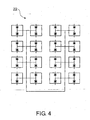
- a receiver antenna 22 can be an array of sixteen elements (this number is chosen for illustrative purposes only) in planar configuration as shown schematically in FIG 4 .
- Other transmitter configurations are possible.
- the line shows the distribution of the LO (Local Oscillator) to 32 mixer diodes.
- One of the diodes in each pair associated with the same antenna element is fed with a quarter wavelength delay. This is to provide an output Q channel.
- the other diode outputs the I channel.
- the antenna elements can be rectangular patches on microstrip.
- a planar antenna structure is easy to manoeuvre behind obstacles, such as cupboards, and covers a larger area than a single element.
- the receiver antenna 22 receives signals in each of the elements in the array at the transmitter/receiver unit 14.
- the received signal Rs is split and distributed by a first set of splitters 18.
- the splitters are conventional broadband Wilkinson power dividers, however, other types of signal distributors may also be used.
- a second set of power splitters 19 distributes a local oscillator signal to mixers 16a and 16b.
- the local oscillator drive to the Q mixer 16b is delayed by 1 ⁇ 4 wavelength in a delay unit 21 with respect to the I mixer 16a.
- Other methods of generating a differential phase shift of 90 degrees, such as quadrature hybrids could be used.
- the received signal Rs is distributed (in phase) to mixers 16a and 16b.
- Mixers 16a and 16b combine reference signal Ref from local oscillator 20 in the signal generator 13, with received signal Rs to extract I and Q IF components of the received signal respectively (0.1-10Hz typically).
- the received microwave frequencies at 24.125 and 61 GHz are processed to extract the I and Q components.
- a Field Effect Transistor (FET) Voltage Controlled Oscillator (VCO) is tuned to an output frequency between 12.0625GHz and 12.2GHz.
- a comb generator harmonic generator
- a second harmonic of 12.0625GHz (24.125GHz) and a fifth harmonic of 12.2GHz (61 GHz) are centred in the two ISM bands.
- the selection of the appropriate harmonics is performed by bandpass filters.
- a total of sixteen vector signals are extracted, representing I and Q components of the received signal from the sixteen elements of the receiver antenna array.
- the antenna data acquisition circuit 17 of the present invention provides complex vector signals containing temporal information about the reflections from a host material such as a wall and potential targets within, such as insects.
- Each complex vector signal further contains information on in-phase and quadrature information (coherent data) and spatial data, since there are sixteen spatial points in the near field pattern at which the signals are detected.
- the complex vector signals containing the above information can be processed to control the field pattern at a receiving antenna, in accordance with the invention.
- the near field pattern of the receiver antenna is controlled and processed to detect the presence, activity, numbers and types of insects in a structure such as a wall.
- FIG 5 there is shown a block diagram of a processing circuit 23 for processing the acquired complex vector signals to control and process the field pattern in accordance with the invention.
- the complex vector signals I and Q represent the real and imaginary components of the complex vector signals.
- the I and Q signals are pre-filtered and amplified by bandpass amplifiers 24 and 25 respectively.
- the filters are analog band pass filters, typically having a lower cut-off frequency of 0.1 Hz and an upper cut-off frequency of up to 100Hz. The purpose of these filters is to reduce aliasing and offsets in the digital processing. Any controlled filtering can be performed by the microcontroller using standard IIR, FIR or DFT/DCT algorithms.
- the filtered and amplified signals are digitised by an analog to digital converter 26.
- a processor means such as a microcontroller 27 receives the digitised signals and performs signal processing.
- the microcontroller 27 is programmed with an algorithm for processing the digitised complex vector signals to control the near field pattern of the receiver antenna 22.
- the microcontroller processes the signals to provide spherical beamforming of the near field pattern.
- the microcontroller performs the following steps:
- the summed signal magnitude and phase distribution is analysed using spectral analysis such as Fourier Transform to spatially locate targets within the grid.
- the raw complex I and Q signals received by the antenna array contain errors due to imperfections in the antenna geometry, differences between array elements, electromagnetic coupling between elements, differences in the response characteristics of mixers, uneven amplitude and phase distribution of LO (reference), and other factors. These imperfections can be corrected by calibration on a "point" transmitting antenna.
- the corrected received signals can then be adjusted to steer and/or focus the array onto a specific target or scan through a large target volume to produce an image. Since most of the detection is likely to involve the presence of inhomogeneous, anisotropic materials such as timber, plasterboard, concrete etc, the field patterns are distorted by the material. In such cases, an additional calibration can be obtained by placing cooperative target or targets in accessible positions, such as behind the wall or in the wall cavity.
- Such cooperative targets may involve modulated scatterers, for easy target recognition and discrimination. Additionally, such cooperative targets can be designed to offer effective scattering cross-sections, commensurate with that of the insects being detected. Insects also present a fluctuating scattering cross-section because of relative movement of their body parts with respect to the electric and magnetic fields of the microwave signal.
- a correction example is described below with reference to FIG 6 .
- Array element B (say) is on the correct radius XB.
- Array element A Its distance from X is XA which is smaller than XB.
- the output of the mixer at A needs to be delayed by an amount equivalent to AC.
- the latter can be translated into a phase shift of (AC/ ⁇ ) ⁇ 360 degrees.
- the measured polar signal at A has the magnitude M A and phase ⁇ A (degrees).
- the corrected phase is ⁇ A +(AC/ ⁇ ) ⁇ 360.
- Similar corrections are performed for all array elements.
- the microprocessor performs this rotation of a complex number.
- a slight magnitude correction can also be performed to compensate for the 1/r 2 signal reduction with range, since the scattered signal from a point target propagates in a spherical wavefront.
- a main advantage of the method is that when focused on a target point, the signals from all the receiver antennas are summed in phase (coherently). The signals from all other targets have random phases and thus on average sum to zero.
- the single large aperture antenna produces a scrambled sum (Fresnel Integral) of all targets and spurious reflections. This applies to desirable targets as well, since RF energy takes different paths to arrive at the single mixer and hence every target suffers from mutual and self interference.
- the objective of the signal processing algorithm is to obtain the maximum amount of coherent spatial information about the targets and their spatial distribution.
- the wavefront from the target is not likely to be truly spherical, mainly because of refraction at the material boundaries. Walls, including studs and noggins, can cause these refractions. Materials such as timber, concrete, plasterboard etc may be inhomogeneous and anisotropic and distort the wavefront in unknown and unpredictable ways.
- phase front can be fine tuned to obtain a more accurate target location by using maximum entropy or fuzzy logic techniques, typically implemented using neural nets. Refraction is compensated by deliberate distortion of the phase front.
- maximum entropy or fuzzy logic techniques typically implemented using neural nets.
- a local maximum is found for a spherical beamfront, with X as the grid point at the centre of the sphere.
- the beamfront can be deliberately perturbed from its spherical shape and the magnitude of the new, coherently summed signal is compared with its previous (unperturbed) value. If the perturbation has resulted in a larger signal, it is accepted and further adjustments are made. Otherwise, it is rejected and another (different) perturbation introduced.
- the rules on the choice of perturbations can be obtained from a neural net, with fuzzy logic, or by similar techniques, such as maximum entropy filtering.
- the number of local maxima indicates the number of scatterers and hence the number of insects.
- the magnitude of each peak indicates the size of each insect.
- a dynamic or close to real time version of the signal processing can be realised by splitting the time series from each mixer 16a, 16b into separate (overlapping or contiguous) segments (frames) and performing similar beamforming analysis on each frame. This can be followed by target tracking, using Hidden Markov chain processing. Hidden Markov tracking is achieved by obtaining overlapping FFT's of the signal time series and assigning probabilities to causal relationships between frequency bins in adjacent FFT's. Eventually deterministic signals are all that survive this process and the probabilities of tracking such events tend to 1.
- Kalman Filtering can be found in numerous publications including, " Estimation of tracking: Principles, techniques and software" by Bar-Shalom Yaakov; Li Xiao-Rong, published by YBS publishing, (1993 by Artech House Inc ).
- Performing a frequency sweep of the local oscillator during the measurement period can enhance the dynamic processing.
- Such a sweep can either be digital (stepped) or analogue (chirp). Either could be used to assist in range resolution and ambiguity resolution of the received near field pattern.
- the resulting signals can be analysed by Gabor or wavelet processing (Frequency-Time FT analysis). Further details of the operation and implementation of Gabor processing may be found in " Gabor representation and signal detection, Gabor analysis and algorithms: Theory and applications" by Friedlander, B.Department of Electrical and Computer Engineering, University of California, Davis, California: Zeira, A.Signal Processing Technology, Palo Alto, California, 1997, Page 353-380 .
- microwave signals at 24 GHz and 61 GHz are received and analysed to determine the type of target detected.
- a comparison of the two near filed patterns can be used to determine a species of insect, type and size.
- Spectral analysis such as a spatial Fourier transform may be performed to determine insect species.
- the "imaging" algorithm discussed in the above description assumes that the target is a point. In a realistic situation, the target has non-zero spatial dimensions and spatial structure. This results in magnitude and phase variations in the scattered wavefront. Magnitude effects arise because signals reflected from different parts of the target have different phases and cause constructive/destructive interference (diffraction pattern). A spatial (discrete) Fourier Transform of the signals from the receiver array can reveal key features of this diffraction pattern and thus, an estimate of the spatial extent of the target. (Under ideal conditions, it is possible to carry this technique to its limit: a full reconstruction of the target geometry by an inversion process.)
- the invention is not limited to imaging applications.
- the method permits the generation and control of an arbitrary receiver near field pattern.
- a zone pattern may be generated for the purposes of detection and counting of zone transits by insects or other moving objects.
- Such techniques are well known in the security industry.
- a standard PIR (Passive Infrared) security sensor usually includes a special Fresnel Lens to generate a fixed zone pattern.
- the present invention provides a control and processing of the field pattern of a receiver antenna array. It provides accurate detection and determination of the type of target in a spatial region in the near field of an antenna.
- nulls and maxima
- the nulls can be made to form concentric circles 10mm apart. Insect movement across these maxima and minima result in fluctuations of the received signal. Temporal analysis of these fluctuations can reveal insect activity.
- This implementation provides information with simpler processing. However, it is difficult to separate the information about insect numbers from insect speed. Hence, this method may be used as a "watchdog operation”. Insect activity above a threshold can be used to trigger the instrument into full imaging mode.
- the placement of maxima and nulls may be directional, in order to compute the direction of motion of the insects directly.
- This mode of operation can be enhanced by adding a mechanism to provoke the target insects into activity.
- the provocation may take the firm of a mechanical disturbance, an acoustic disturbance or an electromagnetic disturbance. It is known that certain acoustic and electromagnetic frequencies disturb insects, which will cause greater movement and therefore lead to stronger and more frequent disturbances of the electromagnetic fields. A thorough exposition on methods of insect control using electromagnetic emissions is presented by Philip Callahan in US patent 5,528,049, (1996 ), which also refers to prior art.
Landscapes
- Physics & Mathematics (AREA)
- Life Sciences & Earth Sciences (AREA)
- General Life Sciences & Earth Sciences (AREA)
- General Physics & Mathematics (AREA)
- Geophysics (AREA)
- Radar Systems Or Details Thereof (AREA)
- Catching Or Destruction (AREA)
Claims (21)
- Processeur de signal pour extraire des signaux (4) de champ proche ou distant d'un réseau d'antennes hyperfréquences (22) pour détecter des insectes en déplacement dans une région (5), comprenant :des moyens de mélange (16a, 16b) adaptés pour extraire des signaux en phase (I) et de quadrature (Q) à partir de signaux (4) reçus par les éléments de réception du réseau d'antennes (22) dans la région (5) ;des moyens de convertisseur caractérisés en ce que les moyens de convertisseur sont adaptés pour combiner les signaux I et Q pour former des vecteurs de signal complexe, ajuster la phase et l'amplitude des vecteurs de signal complexe pour placer et contrôler délibérément les zéros et maxima dans un motif récepteur du réseau d'antennes hyperfréquences, et ajouter les vecteurs de signal complexe pour former des vecteurs totaux ; etdes moyens de processeur (27) adaptés pour traiter les vecteurs totaux pour extraire des informations spatiales cohérentes afin de détecter dans le temps des changements dans les signaux de champ proche ou distant correspondant à un sens de déplacement desdits insectes se déplaçant dans ladite région.
- Processeur de signal selon la revendication 1 dans lequel :un réseau d'éléments de réception reçoivent des signaux transmis dans un champ du réseau dans la région à au moins une fréquence.
- Processeur de signal selon la revendication 2 dans lequel le réseau d'éléments récepteurs est adapté pour recevoir les signaux hyperfréquences reflétés par une cible dans le champ.
- Processeur de signal selon la revendication 1 dans lequel les moyens de processeur sont adaptés pour détecter les insectes se déplaçant dans un champ proche de ladite antenne.
- Processeur de signal selon la revendication 1 dans lequel les moyens de convertisseur compensent les imperfections du signal reçu.
- Processeur de signal selon la revendication 5 dans lequel les moyens de convertisseur ajustent les valeurs d'amplitude et de phase pour produire un motif de champ d'antenne souhaité.
- Processeur de signal selon la revendication 1 dans lequel les moyens de processeur produisent une image des insectes se déplaçant dans le champ.
- Processeur de signal selon la revendication 3 dans lequel le signal hyperfréquences est à une fréquence nominale de 24 GHz.
- Processeur de signal selon la revendication 3 dans lequel le signal hyperfréquences est à une fréquence nominale de 61 GHz.
- Processeur de signal selon la revendication 3 dans lequel un premier signal hyperfréquences est à une fréquence nominale de 24 GHz et un second signal hyperfréquences est à une fréquence nominale de 61 GHz.
- Processeur de signal selon la revendication 1 dans lequel les moyens de processeur incluent des moyens de filtrage pour filtrer ledit signal sommé.
- Processeur de signal selon la revendication 1 dans lequel les moyens de processeur incluent des moyens d'amplification pour amplifier le signal complexe sommé.
- Méthode d'extraction d'informations spatiales cohérentes à partir des signaux reçus par les éléments d'un réseau d'antennes hyperfréquences pour détecter des insectes en déplacement dans une région, incluant les étapes consistant à :mélanger les signaux du réseau d'antennes avec un signal d'un oscillateur local pour extraire des signaux IF en phase (I) et de quadrature (Q) ;combiner les signaux I et Q pour former des vecteurs de signal complexe ;caractérisée en ce que les valeurs de phase et d'amplitude des vecteurs de signal complexe sont ajustées pour placer et contrôler délibérément les zéros et des maxima dans un motif de récepteur du réseau d'antennes hyperfréquences ;sommer les vecteurs de signal complexe ajustés pour former des vecteurs de signal total ; ettraiter les vecteurs de signal total en utilisant des algorithmes d'analyse spectrale pour extraire lesdites informations spatiales cohérentes pour détecter dans le temps des changements dans les signaux de champ proche ou distant correspondant à un sens de déplacement desdits insectes se déplaçant dans ladite région.
- Méthode selon la revendication 13 dans laquelle les algorithmes d'analyse spectrale sont des algorithmes de transformée de Fourier.
- Méthode selon la revendication 13 dans laquelle les valeurs de phase et d'amplitude sont calculées de façon adaptative.
- Méthode selon la revendication 13 dans laquelle les valeurs de phase et d'amplitude sont récupérées dans une table de consultation fixe.
- Méthode selon la revendication 13 incluant en outre l'étape consistant à calculer des valeurs de phase et d'amplitude à partir d'un étalonnage obtenu en focalisant l'antenne du récepteur sur un diffuseur ou des diffuseurs coopératif(s) placé(s) dans des endroits stratégiques ou accessibles dans ou à proximité de la structure faisant l'objet du test.
- Méthode selon la revendication 13 incluant en outre l'étape consistant à calculer les valeurs d'amplitude et de phase qui ajustent les motifs de signal de champ dudit réseau d'antennes pour avoir une géométrie contrôlée de contours d'égale phase et d'égale amplitude.
- Méthode selon la revendication 18 dans laquelle les contours d'égale phase et d'égale amplitude sont arrangés de manière à ce que le mouvement des insectes ait de fortes chances de traverser lesdits contours.
- Méthode selon la revendication 18 incluant en outre l'étape consistant à détecter la modulation de phase ou d'amplitude du signal reçu résultant de fluctuations temporelles des signaux I et Q induits par la traversée des contours d'égale phase et d'égale amplitude.
- Méthode selon la revendication 13 incluant en outre l'étape de conversion des fluctuations de canal I et Q au format polaire et de calcul des fluctuations en amplitude et en phase du signal reçu.
Applications Claiming Priority (3)
| Application Number | Priority Date | Filing Date | Title |
|---|---|---|---|
| AU2002950621 | 2002-08-07 | ||
| AU2002950621A AU2002950621A0 (en) | 2002-08-07 | 2002-08-07 | Near-field antenna array with signal processing |
| PCT/AU2003/000995 WO2004015450A1 (fr) | 2002-08-07 | 2003-08-06 | Antenne reseau a champ proche et a traitement des signaux |
Publications (3)
| Publication Number | Publication Date |
|---|---|
| EP1527360A1 EP1527360A1 (fr) | 2005-05-04 |
| EP1527360A4 EP1527360A4 (fr) | 2007-01-24 |
| EP1527360B1 true EP1527360B1 (fr) | 2014-06-11 |
Family
ID=27809715
Family Applications (1)
| Application Number | Title | Priority Date | Filing Date |
|---|---|---|---|
| EP03783832.3A Expired - Lifetime EP1527360B1 (fr) | 2002-08-07 | 2003-08-06 | Antenne reseau a champ proche et a traitement des signaux |
Country Status (6)
| Country | Link |
|---|---|
| US (1) | US7176828B2 (fr) |
| EP (1) | EP1527360B1 (fr) |
| JP (1) | JP4444825B2 (fr) |
| AU (1) | AU2002950621A0 (fr) |
| WO (1) | WO2004015450A1 (fr) |
| ZA (1) | ZA200501259B (fr) |
Families Citing this family (26)
| Publication number | Priority date | Publication date | Assignee | Title |
|---|---|---|---|---|
| AU2002950621A0 (en) | 2002-08-07 | 2002-09-12 | J I Peston Pty Ltd | Near-field antenna array with signal processing |
| US7434990B2 (en) * | 2002-10-09 | 2008-10-14 | University Of Mississippi | Method to detect termite infestation in a structure |
| US7445377B2 (en) * | 2003-03-12 | 2008-11-04 | Peng Lee | Nondestructive residential inspection method and apparatus |
| US20050259715A1 (en) * | 2003-03-12 | 2005-11-24 | Peng Lee | Nondestructive residential inspection method |
| JP4701384B2 (ja) * | 2005-02-14 | 2011-06-15 | 国立大学法人電気通信大学 | 生物検出装置 |
| US20080295582A1 (en) * | 2005-06-21 | 2008-12-04 | Peng Lee | Nondestructive Residential Inspection Method |
| US7512574B2 (en) * | 2005-09-30 | 2009-03-31 | International Business Machines Corporation | Consistent histogram maintenance using query feedback |
| US7379013B2 (en) * | 2005-10-05 | 2008-05-27 | Banner Engineering Corporation | Detecting objects within a near-field of a frequency modulated continuous wave (FMCW) radar system |
| US7656342B2 (en) * | 2006-10-23 | 2010-02-02 | Stolar, Inc. | Double-sideband suppressed-carrier radar to null near-field reflections from a first interface between media layers |
| US7659847B2 (en) * | 2006-06-29 | 2010-02-09 | Stolar, Inc. | Radar mining guidance control system |
| WO2008018254A1 (fr) * | 2006-08-11 | 2008-02-14 | Brother Kogyo Kabushiki Kaisha | Dispositif de communication sans fil |
| KR100974540B1 (ko) * | 2008-02-18 | 2010-08-11 | 한국과학기술원 | 쿼드러쳐 레이더 장치 |
| US8134494B1 (en) | 2008-06-24 | 2012-03-13 | Raytheon Company | Simulating the mutual performance of an antenna array coupled to an electrical drive circuit |
| WO2010050008A1 (fr) * | 2008-10-29 | 2010-05-06 | 株式会社日立製作所 | Émetteur et récepteur de puissance électrique à région de fresnel variable en fréquence, et système de transmission de puissance électrique |
| US20120268315A1 (en) * | 2009-10-21 | 2012-10-25 | Anatol Zymunt Tirkel | Wide area detection of insects using reflected microwaves |
| CN101900805B (zh) * | 2010-07-02 | 2012-10-24 | 北京理工大学 | 一种球面波成像数学模型及近场效应的补偿方法 |
| US8984800B2 (en) | 2013-03-15 | 2015-03-24 | Technology Sg, L.P. | Radiating systems for affecting insect behavior |
| US9722644B2 (en) | 2015-08-18 | 2017-08-01 | Nokia Solutions And Networks Oy | Frequency switching within time domain digital pre-distortion |
| US10027367B2 (en) * | 2015-08-18 | 2018-07-17 | Nokia Solutions And Networks Oy | Quarter wavelength unit delay and complex weighting coefficient continuous-time filters |
| US9735908B2 (en) | 2015-08-18 | 2017-08-15 | Nokia Solutions And Networks Oy | Adaptive frequency band weighting within time domain |
| US11101915B2 (en) * | 2016-04-25 | 2021-08-24 | University Of Maryland, College Park | System and method for wireless power transfer using time reversed electromagnetic wave propagation |
| US11378679B2 (en) | 2017-08-09 | 2022-07-05 | Georgia Tech Research Corporation | Sensor array imaging device |
| EP3820283A4 (fr) * | 2018-07-10 | 2022-04-13 | University of Maine System Board of Trustees | Système de surveillance d'activité de ruche basé sur un radar doppler |
| CN111383440A (zh) * | 2018-12-29 | 2020-07-07 | 北京骑胜科技有限公司 | 共享交通工具的规范停车方法、装置及电子设备 |
| TWI739181B (zh) * | 2019-10-24 | 2021-09-11 | 國立臺灣大學 | 相位陣列天線校正方法 |
| CN111060534B (zh) * | 2019-12-22 | 2025-02-21 | 中国电波传播研究所(中国电子科技集团公司第二十二研究所) | 一种无损实时探测钢管混凝土柱内部孔洞缺陷的电路装置及其探测方法 |
Family Cites Families (18)
| Publication number | Priority date | Publication date | Assignee | Title |
|---|---|---|---|---|
| US4155259A (en) * | 1978-05-24 | 1979-05-22 | General Electric Company | Ultrasonic imaging system |
| GB2034554B (en) * | 1978-11-09 | 1982-12-15 | Emi Ltd | Holographic imaging using electromagnetic waves |
| US5559516A (en) * | 1981-11-27 | 1996-09-24 | Northrop Grumman Corporation | Dual cancellation interferometric AMTI radar |
| US4810998A (en) * | 1986-10-02 | 1989-03-07 | Hwang Shih Ming | Interruption demonstrating and multi-phase burglar detecting alarm |
| US5036333A (en) * | 1990-06-21 | 1991-07-30 | Hughes Aircraft Company | Antenna-rotation compensation apparatus and method for phased array antennas |
| US5557283A (en) * | 1991-08-30 | 1996-09-17 | Sheen; David M. | Real-time wideband holographic surveillance system |
| WO1997009611A1 (fr) * | 1995-09-06 | 1997-03-13 | J.I. Peston Pty. Ltd. | Detecteur de termites |
| AU693039B2 (en) | 1995-09-06 | 1998-06-18 | McCarron Pty Ltd | Termite detection system |
| US5856804A (en) * | 1996-10-30 | 1999-01-05 | Motorola, Inc. | Method and intelligent digital beam forming system with improved signal quality communications |
| DE19801552A1 (de) | 1998-01-16 | 1999-07-22 | Walter Fisch | Tracking-System |
| EP1039313A1 (fr) * | 1999-03-17 | 2000-09-27 | Valeo Services Limited | Procédé et appareil de détection d'intrusion |
| EP1067397B1 (fr) * | 1999-07-03 | 2006-01-25 | Siemens Schweiz AG | Détecteur de mouvement à effet Doppler |
| SE522564C2 (sv) | 2000-02-01 | 2004-02-17 | Ericsson Telefon Ab L M | Gruppantennkalibrering |
| US6426716B1 (en) * | 2001-02-27 | 2002-07-30 | Mcewan Technologies, Llc | Modulated pulse doppler sensor |
| US6650276B2 (en) * | 2001-07-13 | 2003-11-18 | James C. Lawless | Radar apparatus and method for detecting small slow moving targets |
| AU2002950326A0 (en) * | 2002-07-24 | 2002-09-12 | J I Peston Pty Ltd | An electronic bait station |
| AU2002950621A0 (en) * | 2002-08-07 | 2002-09-12 | J I Peston Pty Ltd | Near-field antenna array with signal processing |
| US7088284B2 (en) * | 2003-11-16 | 2006-08-08 | Preco Electronics, Inc. | Portable proximity-sensing safety device |
-
2002
- 2002-08-07 AU AU2002950621A patent/AU2002950621A0/en not_active Abandoned
-
2003
- 2003-08-06 ZA ZA200501259A patent/ZA200501259B/en unknown
- 2003-08-06 WO PCT/AU2003/000995 patent/WO2004015450A1/fr not_active Ceased
- 2003-08-06 JP JP2004526498A patent/JP4444825B2/ja not_active Expired - Fee Related
- 2003-08-06 EP EP03783832.3A patent/EP1527360B1/fr not_active Expired - Lifetime
-
2005
- 2005-02-04 US US11/052,732 patent/US7176828B2/en not_active Expired - Fee Related
Also Published As
| Publication number | Publication date |
|---|---|
| US20050212691A1 (en) | 2005-09-29 |
| US7176828B2 (en) | 2007-02-13 |
| JP4444825B2 (ja) | 2010-03-31 |
| ZA200501259B (en) | 2006-10-25 |
| EP1527360A4 (fr) | 2007-01-24 |
| JP2005534928A (ja) | 2005-11-17 |
| EP1527360A1 (fr) | 2005-05-04 |
| AU2002950621A0 (en) | 2002-09-12 |
| WO2004015450A1 (fr) | 2004-02-19 |
Similar Documents
| Publication | Publication Date | Title |
|---|---|---|
| EP1527360B1 (fr) | Antenne reseau a champ proche et a traitement des signaux | |
| JP2005534928A5 (fr) | ||
| Cheney | A mathematical tutorial on synthetic aperture radar | |
| US8060339B2 (en) | Multistatic concealed object detection | |
| Geibig et al. | Compact 3D imaging radar based on FMCW driven frequency-scanning antennas | |
| US10761205B2 (en) | Systems for determining target direction and methods therefor | |
| JPH11512178A (ja) | しろありの検出システム | |
| WO2018194477A1 (fr) | Procédé et dispositif de détermination par radiolocalisation des coordonnées et de la vitesse d'un objet | |
| US6133869A (en) | Passive technique for the remote detection of buried objects | |
| Soumekh et al. | SAR-MTI processing of multi-channel airborne radar measurement (MCARM) data | |
| Park et al. | MPSK-MIMO FMCW radar-based indoor multipath recognition | |
| RU2541504C1 (ru) | Устройство селекции движущихся целей для режима перестройки частоты от импульса к импульсу | |
| AU2003249770B2 (en) | Near-field antenna array with signal processing | |
| GB2444989A (en) | Electronically steered radar system for detecting and monitoring slow moving ground based targets | |
| Khan et al. | Cognitive dual coprime frequency diverse array MIMO radar network for target discrimination and main‐lobe interference mitigation | |
| Bleh | W-Band FMCW MIMO radar demonstrator system for 3D imaging | |
| Ashry et al. | Proposed SAR range focusing algorithm based on simulation analysis and SDR implementation | |
| Ahmad et al. | Uwb radar technology | |
| Sheen | Noise analysis for near-field 3D FM-CW radar imaging systems | |
| Jandt et al. | Radar imaging based on multiple non-coherent antennas | |
| Schmitt | Radar imaging with a network of digital noise radar systems | |
| RU94723U1 (ru) | Радиолокационная обзорная станция | |
| Dar | Mono-static and Bi-static MIMO Radar: Targets Localisation | |
| Chen et al. | A coherent through-wall MIMO phased array imaging radar based on time-duplexed switching | |
| Colon-Berrios et al. | Additive Frequency Diverse Active Incoherent Millimeter-Wave Imaging |
Legal Events
| Date | Code | Title | Description |
|---|---|---|---|
| PUAI | Public reference made under article 153(3) epc to a published international application that has entered the european phase |
Free format text: ORIGINAL CODE: 0009012 |
|
| 17P | Request for examination filed |
Effective date: 20050228 |
|
| AK | Designated contracting states |
Kind code of ref document: A1 Designated state(s): AT BE BG CH CY CZ DE DK EE ES FI FR GB GR HU IE IT LI LU MC NL PT RO SE SI SK TR |
|
| AX | Request for extension of the european patent |
Extension state: AL LT LV MK |
|
| EL | Fr: translation of claims filed | ||
| DAX | Request for extension of the european patent (deleted) | ||
| RBV | Designated contracting states (corrected) |
Designated state(s): ES FR GB IT |
|
| REG | Reference to a national code |
Ref country code: HK Ref legal event code: DE Ref document number: 1075495 Country of ref document: HK |
|
| REG | Reference to a national code |
Ref country code: DE Ref legal event code: 8566 |
|
| A4 | Supplementary search report drawn up and despatched |
Effective date: 20061221 |
|
| 17Q | First examination report despatched |
Effective date: 20090915 |
|
| RIC1 | Information provided on ipc code assigned before grant |
Ipc: G01V 8/00 20060101AFI20131024BHEP |
|
| GRAP | Despatch of communication of intention to grant a patent |
Free format text: ORIGINAL CODE: EPIDOSNIGR1 |
|
| INTG | Intention to grant announced |
Effective date: 20131219 |
|
| GRAS | Grant fee paid |
Free format text: ORIGINAL CODE: EPIDOSNIGR3 |
|
| GRAA | (expected) grant |
Free format text: ORIGINAL CODE: 0009210 |
|
| AK | Designated contracting states |
Kind code of ref document: B1 Designated state(s): ES FR GB IT |
|
| REG | Reference to a national code |
Ref country code: GB Ref legal event code: FG4D |
|
| PG25 | Lapsed in a contracting state [announced via postgrant information from national office to epo] |
Ref country code: ES Free format text: LAPSE BECAUSE OF FAILURE TO SUBMIT A TRANSLATION OF THE DESCRIPTION OR TO PAY THE FEE WITHIN THE PRESCRIBED TIME-LIMIT Effective date: 20140611 |
|
| PLBE | No opposition filed within time limit |
Free format text: ORIGINAL CODE: 0009261 |
|
| STAA | Information on the status of an ep patent application or granted ep patent |
Free format text: STATUS: NO OPPOSITION FILED WITHIN TIME LIMIT |
|
| 26N | No opposition filed |
Effective date: 20150312 |
|
| PGFP | Annual fee paid to national office [announced via postgrant information from national office to epo] |
Ref country code: GB Payment date: 20150825 Year of fee payment: 13 |
|
| PGFP | Annual fee paid to national office [announced via postgrant information from national office to epo] |
Ref country code: IT Payment date: 20150827 Year of fee payment: 13 |
|
| REG | Reference to a national code |
Ref country code: HK Ref legal event code: WD Ref document number: 1075495 Country of ref document: HK |
|
| REG | Reference to a national code |
Ref country code: FR Ref legal event code: PLFP Year of fee payment: 14 |
|
| PGFP | Annual fee paid to national office [announced via postgrant information from national office to epo] |
Ref country code: FR Payment date: 20160816 Year of fee payment: 14 |
|
| GBPC | Gb: european patent ceased through non-payment of renewal fee |
Effective date: 20160806 |
|
| PG25 | Lapsed in a contracting state [announced via postgrant information from national office to epo] |
Ref country code: GB Free format text: LAPSE BECAUSE OF NON-PAYMENT OF DUE FEES Effective date: 20160806 |
|
| PG25 | Lapsed in a contracting state [announced via postgrant information from national office to epo] |
Ref country code: IT Free format text: LAPSE BECAUSE OF NON-PAYMENT OF DUE FEES Effective date: 20160806 |
|
| REG | Reference to a national code |
Ref country code: FR Ref legal event code: ST Effective date: 20180430 |
|
| PG25 | Lapsed in a contracting state [announced via postgrant information from national office to epo] |
Ref country code: FR Free format text: LAPSE BECAUSE OF NON-PAYMENT OF DUE FEES Effective date: 20170831 |