EP1527667A1 - Système de guidage d'un véhicule - Google Patents
Système de guidage d'un véhicule Download PDFInfo
- Publication number
- EP1527667A1 EP1527667A1 EP04105338A EP04105338A EP1527667A1 EP 1527667 A1 EP1527667 A1 EP 1527667A1 EP 04105338 A EP04105338 A EP 04105338A EP 04105338 A EP04105338 A EP 04105338A EP 1527667 A1 EP1527667 A1 EP 1527667A1
- Authority
- EP
- European Patent Office
- Prior art keywords
- data
- vehicle
- roll
- tamping
- angle
- Prior art date
- Legal status (The legal status is an assumption and is not a legal conclusion. Google has not performed a legal analysis and makes no representation as to the accuracy of the status listed.)
- Granted
Links
- 238000013500 data storage Methods 0.000 claims abstract description 5
- 238000010276 construction Methods 0.000 abstract description 2
- 230000005484 gravity Effects 0.000 description 4
- 238000000034 method Methods 0.000 description 4
- 230000003068 static effect Effects 0.000 description 4
- 230000001133 acceleration Effects 0.000 description 3
- 238000010586 diagram Methods 0.000 description 3
- 238000012876 topography Methods 0.000 description 3
- 241001124569 Lycaenidae Species 0.000 description 2
- 239000011159 matrix material Substances 0.000 description 2
- 238000005096 rolling process Methods 0.000 description 2
- 239000002689 soil Substances 0.000 description 2
- 101100310323 Caenorhabditis elegans sinh-1 gene Proteins 0.000 description 1
- 238000001514 detection method Methods 0.000 description 1
- 230000003292 diminished effect Effects 0.000 description 1
- 239000000835 fiber Substances 0.000 description 1
Images


Classifications
-
- A—HUMAN NECESSITIES
- A01—AGRICULTURE; FORESTRY; ANIMAL HUSBANDRY; HUNTING; TRAPPING; FISHING
- A01B—SOIL WORKING IN AGRICULTURE OR FORESTRY; PARTS, DETAILS, OR ACCESSORIES OF AGRICULTURAL MACHINES OR IMPLEMENTS, IN GENERAL
- A01B79/00—Methods for working soil
- A01B79/005—Precision agriculture
-
- A—HUMAN NECESSITIES
- A01—AGRICULTURE; FORESTRY; ANIMAL HUSBANDRY; HUNTING; TRAPPING; FISHING
- A01B—SOIL WORKING IN AGRICULTURE OR FORESTRY; PARTS, DETAILS, OR ACCESSORIES OF AGRICULTURAL MACHINES OR IMPLEMENTS, IN GENERAL
- A01B69/00—Steering of agricultural machines or implements; Guiding agricultural machines or implements on a desired track
- A01B69/007—Steering or guiding of agricultural vehicles, e.g. steering of the tractor to keep the plough in the furrow
- A01B69/008—Steering or guiding of agricultural vehicles, e.g. steering of the tractor to keep the plough in the furrow automatic
-
- G—PHYSICS
- G05—CONTROLLING; REGULATING
- G05D—SYSTEMS FOR CONTROLLING OR REGULATING NON-ELECTRIC VARIABLES
- G05D1/00—Control of position, course, altitude or attitude of land, water, air or space vehicles, e.g. using automatic pilots
- G05D1/02—Control of position or course in two dimensions
- G05D1/021—Control of position or course in two dimensions specially adapted to land vehicles
- G05D1/0268—Control of position or course in two dimensions specially adapted to land vehicles using internal positioning means
- G05D1/0274—Control of position or course in two dimensions specially adapted to land vehicles using internal positioning means using mapping information stored in a memory device
-
- G—PHYSICS
- G05—CONTROLLING; REGULATING
- G05D—SYSTEMS FOR CONTROLLING OR REGULATING NON-ELECTRIC VARIABLES
- G05D1/00—Control of position, course, altitude or attitude of land, water, air or space vehicles, e.g. using automatic pilots
- G05D1/02—Control of position or course in two dimensions
- G05D1/021—Control of position or course in two dimensions specially adapted to land vehicles
- G05D1/0276—Control of position or course in two dimensions specially adapted to land vehicles using signals provided by a source external to the vehicle
- G05D1/0278—Control of position or course in two dimensions specially adapted to land vehicles using signals provided by a source external to the vehicle using satellite positioning signals, e.g. GPS
-
- G—PHYSICS
- G05—CONTROLLING; REGULATING
- G05D—SYSTEMS FOR CONTROLLING OR REGULATING NON-ELECTRIC VARIABLES
- G05D1/00—Control of position, course, altitude or attitude of land, water, air or space vehicles, e.g. using automatic pilots
- G05D1/08—Control of attitude, i.e. control of roll, pitch, or yaw
- G05D1/0891—Control of attitude, i.e. control of roll, pitch, or yaw specially adapted for land vehicles
Definitions
- the invention relates to a guide system for a vehicle, in be compensated for variations in ground level.
- a position-determining receiver eg receiver for the Global Positioning System, GPS
- GPS Global Positioning System
- a position-determining receiver alone poses typically no data regarding the bank (roll angle) and the inclination between the longitudinal axis of the vehicle and the Horizontal (tamping angle) ready.
- hilly terrain or other work surfaces that are not essentially flat, may be the lack of data regarding rolling and tamping angles contribute to a navigation control of the vehicle, the worse than desired or required to meet an im Essentially straight path or another path with one Target level to follow accuracy.
- the additional sensors and the data processing means for processing the detected Data means additional costs for the vehicle. Besides, they are the additional sensors generally capable of that current orientation (for example, the current roll and Tamping angle) of the vehicle to capture, but not the too expected orientation (eg the future roll and Pitch angle) of the vehicle. Due to the Time delay between the detection of the roll and tamping data and a response to the collected data, it is possible that the additional sensors are not a sensible solution for one provide enhanced navigation control of a vehicle.
- the object underlying the invention is seen therein to provide an improved guidance system for a vehicle, in which variations in ground level are compensated.
- elevation data and associated position data to provide for a surface to be worked.
- a respective one Position of a vehicle on the surface to be machined certainly.
- the roll and / or the corresponding position Tamping data are based on the obtained Height data estimated or determined.
- the vehicle is based on the estimated roll data, the estimated tamping data or both led so that it follows a desired way.
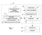
- the electronic system 10 comprises a Vehicle a position-determining receiver 12 and a Data storage device 18 connected to a data processor 20 is.
- the data processor 20 is in turn with a steering control 26 connected.
- the steering control 26 is provided with a steering system 27 connected to the vehicle.
- the position determining receiver 12 may be a receiver for the Global Positioning System (GPS), a Loran receiver, a Loran C receiver or any other Navigation receivers to be geographic coordinates of Receiver 12 or the vehicle to which it is attached, provide.
- GPS Global Positioning System
- Loran Loran C receiver
- any other Navigation receivers to be geographic coordinates of Receiver 12 or the vehicle to which it is attached, provide.
- the data storage device 18 may relate altitude data Location data (eg a digital elevation model) to one save the working area.
- the digital elevation model the surface to be machined into one Split matrix of cells.
- the cells can be used, for example, by be uniform in size and shape.
- Each cell can use location data and elevation data 16 linked.
- the location data for a cell can be used as geographic coordinates or position coordinates be expressed with a center of the cell or linked to a boundary of the cell.
- the topography of the surface to be processed can be determined by the Vehicle or other equipment before completing a planned path or one with the surface to be processed connected task.
- the exploration or other Technique provides location data versus height on a cell basis ready for the surface to be processed.
- the place data and associated altitude data 16 can be used as a digital elevation model, Database file, lookup table or other representation be expressed.
- the data processor 20 may include a roll angle estimator 22, a Stomp angle estimator 24 and a compensator 25 include.
- Roll angle estimator 22 estimates roll data for the vehicle based on one or more of the following data: Location data, altitude data 16, a current location of the Vehicle, an expected position of the vehicle, the scalar or vectorial vehicle speed, the direction of the Vehicle and a path plan.
- the pitch angle estimator 24 estimates tamping data for the vehicle based on or several of the following data: location data, elevation data 16, one current position of the vehicle, an expected position of the vehicle, the vehicle speed, the direction of the vehicle Vehicle and a path plan.
- the compensator 25 is equal to any variations in the Rollund Tamping data of the vehicle made by local or global Changes in the terrain or the topography of the edited Area are conditional.
- the Compensator 25 raw route data for the vehicle and gives one compensated roadmap for the vehicle from the current Tamping data and / or the current roll data and / or the expected tamping data and / or the expected rolling data of the Vehicle considered.
- the route plan represents positions and directions of travel of the vehicle, being substantially flat or ideal terrain is assumed, the compensated Route plan positions and directions of the vehicle represents where the current terrain with hills, waves or other variations in the inclination or height of the soil are balanced.
- the compensator 25 sends the compensated Path plan or (related) compensation data to the Steering control 26 to the vehicle along a desired path or to direct a route.
- the steering controller 26 controls the Steering and direction of travel of the vehicle (eg the direction of travel along a planned path) based on the steering system 27 on a route plan and compensation data.
- the steering control 26 forms an interface between the electronic system 10 of the vehicle and the steering system 27.
- Das Steering system 27 may be a hydraulic steering system, a hydraulic supported steering system, an electric steering system, a mechanical steering system, driven by a gearbox Steering system, or the like, with the vehicle connected is.
- a hydraulically assisted or electric Steering system can be set up, for example a mechanical steering system, geared via a gearbox Steering system or a steering system with a rack and a To support gear.
- Hydraulic and hydraulic Supported steering systems can be electromechanical actuators include to actuate valves or otherwise the hydraulic elements of the steering system 27 to assist.
- Electric steering systems can be electric motors (direct or indirectly via connections) use the orientation of a or change several wheels, resulting in ground contact are located. Compensation data or corresponding correction signals for example, to a steering motor driver or another Steering control 26 are sent.
- FIG. 2 shows a flowchart of a method for guiding a vehicle that provides improved compensation of Variations in ground level include.
- the method according to FIG. 2 begins with step S100.
- step S100 height data and associated location data for generates a surface to be processed.
- the surface to be processed may be in a group of cells of essentially the same size and form are split.
- the surface to be processed can For example, in a matrix with substantially rectangular or square cells are divided. Every cell is with Location data and elevation data of the cell linked.
- the location data of For example, cells can have geographic coordinates that define a cell border, and the Height data of the cell can be the height, inclination or other Represent properties of the soil.
- Inclination data relating to location data or altitude data related to Location data is about the area to be processed and preferably determined within each cell.
- a digital altitude map can based on a collection of elevation data of the cells and the associated location data of the cells are generated.
- the figures 6 and 7 are illustrative examples of digital elevation maps, which could be generated according to step S100.
- the position determining receiver 12 determines Location data, including a respective position of the vehicle at an appropriate time within the to be processed Area.
- the respective position may be one or more of the following Positions include: (1) a current position of the Vehicle, (2) a planned position of the vehicle and (3) a Path plan showing the current position and the planned position of the vehicle interconnects.
- an estimator estimates the roll data and / or the Tamping data based on the determined, respective position and the ascertained altitude data (eg digital altitude map).
- the Roll angle estimator 22 may, for example, roll data for the Estimate the vehicle with the appropriate location or Position data for a path are linked.
- ram angle estimator 24 may provide vehicle tamping data estimate that with appropriate location or position data are linked.
- Step S104 may include one or more of following steps include: First, the position data used to read appropriate, associated elevation data, the previously detected. Second, the roll data, Tamping data, or both based on the height data found certainly.
- the determination of the roll or tamped data on the basis of the determined height data can be carried out according to different, alternatively usable equations or formulas.
- the roll angle estimator 22 may the roll angle for the cells along a planned path or of a raw route during ramming angle estimator 24 the ramming angle for the cells along the planned path or Can determine crude travel.
- static Force Equilibrium Equations are used to determine the above equations to refine or replace the roll and pitch angle.
- the static force equilibrium equations and the dynamic ones Equilibrium equations may include one or more of the consider the following variables: vehicle geometry (size), Tire geometry, vehicle mass and load, Vehicle tire spacing in the transverse and longitudinal direction, on the tires the vehicle acting forces and speeds and Accelerations of the vehicle and its components.
- the compensator 25 sets compensation data ready based on at least one of the following: (1) estimated roll data, (2) estimated tamping data, (3) the planned path of the vehicle, (4) the position of the vehicle, (5) the speed amount of the vehicle, (6) the vectorial Speed (i.e., speed and direction) of the Vehicle, (7) acceleration or deceleration of the vehicle when Follow a desired path.
- the estimated roll data, the estimated ramming data or both are used to Compensation data or other corrective input for the To generate steering control 26. It is assumed that Compensation data for any cell of (a) the direction entering and entering the vehicle into the cell, (b) the direction of leaving and the place of leaving the Cell, (c) the vehicle speed and (d) a total planned way of the vehicle.
- step S108 the steering controller 26 controls the steering system 27 based on the compensation data of the compensator 25 and the Location data from the position-determining receiver 12, so that the Vehicle a planned route (such as a substantially rectilinear path), unaffected by hills or others Variations in the height of the terrain.
- the Compensation data can be shaking, wobbling or others unwanted deviations of the position of the vehicle on the current path diminished by the desired path, the otherwise occur.
- the compensation data represent one Compensation to compensate for the difference between a current, location-based leadership and an achieved, planned route (eg a substantially straightforward path).
- FIG. 3 shows a rear view of a vehicle 30 with tires 32 which rest on a laterally inclined floor 48.
- the Roll angle 34 ( ⁇ ) is with respect to the center of gravity 40 of Vehicle 30 defined.
- the crest line of the roll angle 34 extends through the center of gravity 40 of the vehicle 30.
- a first page 44 (shown by dashed lines) of the Roll angle 34 is substantially parallel to unsatisfied or level ground, while the other side (by the arrow in Y direction characterized) of the roll angle 34 substantially parallel to the lateral inclination 46 of the inclined bottom runs.
- the Z-axis 42 outputs a normal force of the vehicle 30 on the inclined floor 48 again.
- FIG. 4 shows a side view of the vehicle 30 Tire 32, which on the longitudinally inclined bottom 49 rest.
- the pitch angle 54 ( ⁇ ) is opposite to the center of gravity 40 of the vehicle 30 defined.
- the apex of the Stomp angle 54 extends through the center of gravity 40 of Vehicle 30.
- One side 39 of the pitch angle 54 is in Substantially parallel to inadequate or even ground while the other side of the ram angle 52 substantially parallel extends to the lateral inclination of the inclined floor.
- the Z axis 42 indicates a normal force of the vehicle 30 on the inclined bottom 48 again.
- Figure 5 illustrates the slope of the terrain of at least a portion (eg, a cell) of the surface to be processed.
- the slope (H) includes a lateral slope 46 (H y ) and a longitudinal slope (H x ) 50.
- Figs. 5a and 5b show an aspect representing the change of the inclination (H) or the first derivative of the inclination.
- each cell may be defined by a slope (H) comprising the following components: an inclination 50 in the longitudinal direction (H x ) and a lateral inclination 46 (H y ).
- the aspect 51 or aspect angle ( ⁇ ) is the direction of the maximum inclination measured with respect to the X-axis.
- the aspect angle is the angle between the X-axis and the maximum slope.
- the direction of travel can be defined to coincide with the X-axis.
- the above equations may be static Force Equilibrium Equations and Dynamic Equations be changed or accompanied, focusing on the on the refer to working surface vehicle 30.
- the static force equilibrium equations and the dynamic ones Equations can have one or more of the following variables consider: (a) vehicle geometry and dimensions, (b) Vehicle mass and load, (c) on the tires of the vehicle acting forces (d) speeds and accelerations of the Vehicle, and (e) other sizes or specifications of the Vehicle.
- Figure 6 illustrates a first digital elevation map in graphical form. It will be understood that any digital captured map may be represented as a table, a relational database or an inverted file.
- the digital elevation model divides an area to be processed into uniformly shaped cells (eg, rectangles or squares). For each cell, a uniform value for height and slope can be assumed. The cell size may depend on the availability of topographic data for the area being worked on. A cell size that is less than or equal to the vehicle length is preferred in order to obtain a sufficiently accurate estimate of the pitch and roll data.
- the digital first height map of Figure 6 divides the area to be processed into an area of five by five rectangular cells, each cell having elevation data (E) and location data (L). For example, the identifier for the cell in row 1, column 1 is connected to E 1,1 and L 1,1 , the identifier for the cell in row 2, column 2 is connected to E 2,2 and L 2,2 , etc ..
- FIG. 7 shows a second digital elevation map in graphical form.
- the digital second height map of Figure 7 divides the area to be processed into an area of four by six rectangular cells.
- Each cell within the second digital elevation map may be associated with or associated with corresponding uniform elevation data (E), slope data (S), aspect data (A), and location data (L).
- E uniform elevation data
- S slope data
- A aspect data
- L location data
- the identifier for the cell in row 1, column 1 is associated with E 1,1, L 1,1 S 1,1 and A 1,1 , etc.
- FIGS. 6 and 7 are illustrative examples of representations of a digital one elevation model; Real representations may vary in size, shape, number of cells, and / or number of variables per cell.
Landscapes
- Engineering & Computer Science (AREA)
- Life Sciences & Earth Sciences (AREA)
- Radar, Positioning & Navigation (AREA)
- Remote Sensing (AREA)
- Environmental Sciences (AREA)
- Soil Sciences (AREA)
- Mechanical Engineering (AREA)
- Aviation & Aerospace Engineering (AREA)
- Physics & Mathematics (AREA)
- General Physics & Mathematics (AREA)
- Automation & Control Theory (AREA)
- Control Of Driving Devices And Active Controlling Of Vehicle (AREA)
- Navigation (AREA)
- Control Of Position, Course, Altitude, Or Attitude Of Moving Bodies (AREA)
Applications Claiming Priority (2)
| Application Number | Priority Date | Filing Date | Title |
|---|---|---|---|
| US10/696,788 US7593798B2 (en) | 2003-10-30 | 2003-10-30 | Vehicular guidance system having compensation for variations in ground elevation |
| US696788 | 2010-01-29 |
Publications (2)
| Publication Number | Publication Date |
|---|---|
| EP1527667A1 true EP1527667A1 (fr) | 2005-05-04 |
| EP1527667B1 EP1527667B1 (fr) | 2013-04-24 |
Family
ID=34423378
Family Applications (1)
| Application Number | Title | Priority Date | Filing Date |
|---|---|---|---|
| EP04105338.0A Expired - Lifetime EP1527667B1 (fr) | 2003-10-30 | 2004-10-27 | Système de guidage d'un véhicule |
Country Status (2)
| Country | Link |
|---|---|
| US (2) | US7593798B2 (fr) |
| EP (1) | EP1527667B1 (fr) |
Cited By (4)
| Publication number | Priority date | Publication date | Assignee | Title |
|---|---|---|---|---|
| WO2008055732A1 (fr) * | 2006-11-10 | 2008-05-15 | Robert Bosch Gmbh | Amélioration du confort de braquage lors de déplacements transversaux sur des surfaces inclinées |
| EP2273334A1 (fr) * | 2009-06-22 | 2011-01-12 | BAE Systems PLC | Détection de terrain |
| US11596093B2 (en) | 2015-11-17 | 2023-03-07 | Lagos Computerservice Gmbh | Method for predictively generating data for controlling a travel path and an operating sequence for agricultural vehicles and machines |
| EP4268557A1 (fr) | 2022-04-27 | 2023-11-01 | CLAAS Selbstfahrende Erntemaschinen GmbH | Procédé de génération de données pour commander une machine de travail agricole autonome |
Families Citing this family (27)
| Publication number | Priority date | Publication date | Assignee | Title |
|---|---|---|---|---|
| US7272474B1 (en) * | 2004-03-31 | 2007-09-18 | Carnegie Mellon University | Method and system for estimating navigability of terrain |
| US20100013615A1 (en) * | 2004-03-31 | 2010-01-21 | Carnegie Mellon University | Obstacle detection having enhanced classification |
| US10378896B2 (en) * | 2006-02-27 | 2019-08-13 | Trimble Inc. | Method and system for planning the path of an agricultural vehicle |
| US8565984B2 (en) * | 2007-03-16 | 2013-10-22 | Deere & Comany | System and method of steering for a work vehicle towing a towed implement on lateral slopes |
| US8260499B2 (en) * | 2007-05-01 | 2012-09-04 | Deere & Company | Automatic steering system and method for a work vehicle with feedback gain dependent on a sensed payload |
| KR20110069331A (ko) * | 2009-12-17 | 2011-06-23 | 한국전자통신연구원 | 고도 정보를 이용한 차량 엔진 제어 장치 및 그 방법 |
| FI121762B (fi) | 2010-05-10 | 2011-03-31 | Sandvik Mining & Constr Oy | Menetelmä ja laitteisto kaivosajoneuvon paikantamisen järjestämiseksi |
| US9668400B2 (en) * | 2011-07-05 | 2017-06-06 | Kongskilde Industries A/S | Automatic guidance system for pull-type agricultural implement |
| US8589013B2 (en) | 2011-10-25 | 2013-11-19 | Jaybridge Robotics, Inc. | Method and system for dynamically positioning a vehicle relative to another vehicle in motion |
| US9020757B2 (en) * | 2012-05-11 | 2015-04-28 | Trimble Navigation Limited | Path planning autopilot |
| US8924096B2 (en) | 2012-10-31 | 2014-12-30 | Caterpillar Inc. | Implement controller having angular rate correction |
| US20140278696A1 (en) * | 2013-03-15 | 2014-09-18 | Deere & Company | Methods and apparatus to determine work paths for machines |
| US9188986B2 (en) | 2013-10-01 | 2015-11-17 | Jaybridge Robotics, Inc. | Computer-implemented method and system for dynamically positioning a vehicle relative to another vehicle in motion for on-the-fly offloading operations |
| US9970767B2 (en) | 2015-09-22 | 2018-05-15 | Caterpillar Inc. | Stabilization based path planning |
| WO2018086764A1 (fr) | 2016-11-10 | 2018-05-17 | Lacos Computerservice Gmbh | Procédé de génération de données de manière prédictive destiné à la commande d'une voie et d'une séquence de fonctionnement pour véhicules et machines agricoles |
| US11448524B2 (en) | 2016-04-07 | 2022-09-20 | Phoenix America Inc. | Multipole magnet for use with a pitched magnetic sensor |
| DE102017204239A1 (de) * | 2017-03-14 | 2018-09-20 | Deere & Co. | Verfahren zur Prädiktion einer Topographie-Information |
| CN109991972A (zh) * | 2017-12-29 | 2019-07-09 | 长城汽车股份有限公司 | 控制车辆行驶的方法、装置、车辆及可读存储介质 |
| DE102019135225B4 (de) | 2019-12-19 | 2023-07-20 | Wirtgen Gmbh | Verfahren zum Abfräsen von Verkehrsflächen mit einer Fräswalze, sowie Fräsmaschine zur Durchführung des Verfahrens zum Abfräsen von Verkehrsflächen |
| US12016257B2 (en) | 2020-02-19 | 2024-06-25 | Sabanto, Inc. | Methods for detecting and clearing debris from planter gauge wheels, closing wheels and seed tubes |
| US11493586B2 (en) * | 2020-06-28 | 2022-11-08 | T-Mobile Usa, Inc. | Mobile proximity detector for mobile electronic devices |
| US12461083B2 (en) | 2020-08-03 | 2025-11-04 | Sabanto, Inc. | Methods for improved agricultural procedures |
| CN113126628A (zh) * | 2021-04-26 | 2021-07-16 | 上海联适导航技术股份有限公司 | 一种农机自动驾驶的方法、系统、设备及可读存储介质 |
| CN114916276A (zh) * | 2022-04-18 | 2022-08-19 | 张景燕 | 一种根据土层厚度进行土地平整的方法 |
| US12571170B2 (en) | 2022-04-21 | 2026-03-10 | Wirtgen Gmbh | Differential milling and paving |
| US12416123B2 (en) | 2023-04-11 | 2025-09-16 | Wirtgen Gmbh | Automated sensor switching |
| US12542014B2 (en) | 2024-06-19 | 2026-02-03 | Wirtgen Gmbh | Plausibility check |
Citations (2)
| Publication number | Priority date | Publication date | Assignee | Title |
|---|---|---|---|---|
| DE19544112A1 (de) * | 1995-11-27 | 1997-05-28 | Claas Ohg | Verfahren zur Generierung digitaler Geländemodelle |
| WO2000024239A1 (fr) | 1998-10-27 | 2000-05-04 | Agsystems Pty. Ltd. | Appareil et procede de positionnement de vehicules |
Family Cites Families (39)
| Publication number | Priority date | Publication date | Assignee | Title |
|---|---|---|---|---|
| US2801511A (en) * | 1954-05-17 | 1957-08-06 | Deere & Co | Leveling control system for agricultural machine |
| US4416109A (en) * | 1983-01-03 | 1983-11-22 | Simplicity Manufacturing, Inc. | Mower attachment draft linkage responding to ground contour |
| US4707971A (en) * | 1986-04-21 | 1987-11-24 | Deweze Manufacturing, Inc. | Slope mower |
| DE69131270T2 (de) * | 1990-10-01 | 1999-12-02 | Mannesmann Vdo Ag | Verfahren zur Speicherung eines topologischen Netzwerkes und Verfahren und Geräte, um eine Reihe von 1-Zellen zu identifizieren |
| US5534875A (en) * | 1993-06-18 | 1996-07-09 | Adroit Systems, Inc. | Attitude determining system for use with global positioning system |
| US5415586A (en) * | 1993-11-17 | 1995-05-16 | R. A. Hanson Company, Inc. | Combine harvester leveling system, combine harvester header adjusting system, and pivoting chain drive system |
| US5471391A (en) * | 1993-12-08 | 1995-11-28 | Caterpillar Inc. | Method and apparatus for operating compacting machinery relative to a work site |
| US5467271A (en) * | 1993-12-17 | 1995-11-14 | Trw, Inc. | Mapping and analysis system for precision farming applications |
| US5404661A (en) * | 1994-05-10 | 1995-04-11 | Caterpillar Inc. | Method and apparatus for determining the location of a work implement |
| US5438771A (en) * | 1994-05-10 | 1995-08-08 | Caterpillar Inc. | Method and apparatus for determining the location and orientation of a work machine |
| US6236907B1 (en) * | 1995-05-30 | 2001-05-22 | Ag-Chem Equipment Co., Inc. | System and method for creating agricultural decision and application maps for automated agricultural machines |
| US5928309A (en) * | 1996-02-05 | 1999-07-27 | Korver; Kelvin | Navigation/guidance system for a land-based vehicle |
| US5978723A (en) * | 1996-11-22 | 1999-11-02 | Case Corporation | Automatic identification of field boundaries in a site-specific farming system |
| US5987371A (en) * | 1996-12-04 | 1999-11-16 | Caterpillar Inc. | Apparatus and method for determining the position of a point on a work implement attached to and movable relative to a mobile machine |
| USH1997H1 (en) * | 1997-01-27 | 2001-10-02 | The United States Of America As Represented By The Secretary Of The Navy | Apparatus and method of concomitant scenario topography with the aid of a digital computer |
| US5860480A (en) * | 1997-04-08 | 1999-01-19 | Caterpillar Inc. | Method and apparatus for determining pitch and ground speed of an earth moving machines |
| WO1998046065A1 (fr) * | 1997-04-16 | 1998-10-22 | Carnegie Mellon University | Machine agricole de recolte commandee par robot |
| US5987383C1 (en) * | 1997-04-28 | 2006-06-13 | Trimble Navigation Ltd | Form line following guidance system |
| US6052647A (en) * | 1997-06-20 | 2000-04-18 | Stanford University | Method and system for automatic control of vehicles based on carrier phase differential GPS |
| US6028550A (en) * | 1997-08-08 | 2000-02-22 | Trimble Navigation Limited | Vehicle guidance system using signature zones to detect travel path |
| DE19830858A1 (de) * | 1998-07-10 | 2000-01-13 | Claas Selbstfahr Erntemasch | Vorrichtung und Verfahren zur Bestimmung einer virtuellen Position |
| US6199000B1 (en) * | 1998-07-15 | 2001-03-06 | Trimble Navigation Limited | Methods and apparatus for precision agriculture operations utilizing real time kinematic global positioning system systems |
| US6286606B1 (en) * | 1998-12-18 | 2001-09-11 | Caterpillar Inc. | Method and apparatus for controlling a work implement |
| US6112145A (en) * | 1999-01-26 | 2000-08-29 | Spectra Precision, Inc. | Method and apparatus for controlling the spatial orientation of the blade on an earthmoving machine |
| US6182007B1 (en) * | 1999-03-11 | 2001-01-30 | Lockheed Martin Corp. | Incorporating aspect angle into route planners |
| US6236916B1 (en) * | 1999-03-29 | 2001-05-22 | Caterpillar Inc. | Autoguidance system and method for an agricultural machine |
| US6275758B1 (en) * | 1999-06-29 | 2001-08-14 | Caterpillar Inc. | Method and apparatus for determining a cross slope of a surface |
| US20020022924A1 (en) * | 2000-03-07 | 2002-02-21 | Begin John David | Propagation of position with multiaxis accelerometer |
| US6445983B1 (en) * | 2000-07-07 | 2002-09-03 | Case Corporation | Sensor-fusion navigator for automated guidance of off-road vehicles |
| US6360169B1 (en) * | 2000-09-07 | 2002-03-19 | Umesh Dudabey | System for determining and tracking changes in location |
| GB0203688D0 (en) * | 2002-02-16 | 2002-11-13 | Bae Systems Combat And Radar S | Ship motion predictor |
| US6804584B2 (en) * | 2002-03-20 | 2004-10-12 | Ford Global Technologies, Llc | Method for determining the roll angle of a vehicle using an estimation of road bank angle |
| US6711838B2 (en) * | 2002-07-29 | 2004-03-30 | Caterpillar Inc | Method and apparatus for determining machine location |
| US6728607B1 (en) * | 2002-10-03 | 2004-04-27 | Deere & Company | Method and system for determining an energy-efficient path of a machine |
| DE10251038A1 (de) * | 2002-11-02 | 2004-05-19 | Robert Bosch Gmbh | Fahrzeugführungssystem |
| US6907347B2 (en) * | 2002-11-21 | 2005-06-14 | Ford Global Technologies, Llc | Systems and method for estimating speed and pitch sensor errors |
| US7277837B2 (en) * | 2003-08-27 | 2007-10-02 | Hayes, Seay, Mattern & Mattern, Inc. | Method for flow analysis utilizing cell elevation topology |
| US7139651B2 (en) * | 2004-03-05 | 2006-11-21 | Modular Mining Systems, Inc. | Multi-source positioning system for work machines |
| US8019513B2 (en) * | 2006-05-18 | 2011-09-13 | Applied Perception Inc. | Vision guidance system and method for identifying the position of crop rows in a field |
-
2003
- 2003-10-30 US US10/696,788 patent/US7593798B2/en not_active Expired - Lifetime
-
2004
- 2004-10-27 EP EP04105338.0A patent/EP1527667B1/fr not_active Expired - Lifetime
-
2009
- 2009-08-17 US US12/542,333 patent/US7844380B2/en not_active Expired - Lifetime
Patent Citations (2)
| Publication number | Priority date | Publication date | Assignee | Title |
|---|---|---|---|---|
| DE19544112A1 (de) * | 1995-11-27 | 1997-05-28 | Claas Ohg | Verfahren zur Generierung digitaler Geländemodelle |
| WO2000024239A1 (fr) | 1998-10-27 | 2000-05-04 | Agsystems Pty. Ltd. | Appareil et procede de positionnement de vehicules |
Cited By (5)
| Publication number | Priority date | Publication date | Assignee | Title |
|---|---|---|---|---|
| WO2008055732A1 (fr) * | 2006-11-10 | 2008-05-15 | Robert Bosch Gmbh | Amélioration du confort de braquage lors de déplacements transversaux sur des surfaces inclinées |
| EP2273334A1 (fr) * | 2009-06-22 | 2011-01-12 | BAE Systems PLC | Détection de terrain |
| US11596093B2 (en) | 2015-11-17 | 2023-03-07 | Lagos Computerservice Gmbh | Method for predictively generating data for controlling a travel path and an operating sequence for agricultural vehicles and machines |
| EP4268557A1 (fr) | 2022-04-27 | 2023-11-01 | CLAAS Selbstfahrende Erntemaschinen GmbH | Procédé de génération de données pour commander une machine de travail agricole autonome |
| DE102022110116A1 (de) | 2022-04-27 | 2023-11-02 | Claas Selbstfahrende Erntemaschinen Gmbh | Verfahren zum Erzeugen von Daten zum Steuern einer autonomen landwirtschaftlichen Arbeitsmaschine |
Also Published As
| Publication number | Publication date |
|---|---|
| US20090292412A1 (en) | 2009-11-26 |
| US20050096802A1 (en) | 2005-05-05 |
| US7593798B2 (en) | 2009-09-22 |
| US7844380B2 (en) | 2010-11-30 |
| EP1527667B1 (fr) | 2013-04-24 |
Similar Documents
| Publication | Publication Date | Title |
|---|---|---|
| EP1527667B1 (fr) | Système de guidage d'un véhicule | |
| EP0970595B2 (fr) | Dispositif et procédé pour déterminer une position virtuelle | |
| DE112007002946B4 (de) | Fahrzeugsteuervorrichtung | |
| WO2019101651A1 (fr) | Procédé et dispositif de fonctionnement d'un système mobile | |
| DE102018221265B4 (de) | Verfahren und System zum Erfassen eines auf ein Fahrzeug einwirkenden Windes | |
| DE112014001807B4 (de) | Integrierte Gefälle- und Neigungsschätzung unter Verwendung einer Trägheitsmessvorrichtung mit drei Achsen | |
| DE102015116268B4 (de) | Spurbegrenzungslinieninformationserlangungsvorrichtung | |
| DE112019002782T5 (de) | Eine vorrichtung und ein verfahren zur steuerung der lenkung | |
| DE102018222531A1 (de) | Verfahren zum wenigstens teilautomatisierten Steuern des Kraftfahrzeugs während eines Einpark- oder Ausparkvorgangs, Steuervorrichtung sowie Kraftfahrzeug | |
| DE112019000873T5 (de) | System und Verfahren zum Erzeugen eines Zielpfades für ein Fahrzeug | |
| DE102016102002A1 (de) | Verbesserung einer Fahrzeugbewegungsabschätzung mit Radardaten | |
| DE102004003877A1 (de) | Detektor für Fahrzeugverhalten, Verarbeitungssystem im Fahrzeug, Kalibriereinrichtung für Erfassungsinformationen und Prozessor im Fahrzeug | |
| DE102018221264B4 (de) | Verfahren und System zum Erfassen eines Windes in einem geografischen Bereich | |
| DE102021204257A1 (de) | Bodeneingriffswerkzeugsteuersystem und -verfahren | |
| DE112019006225T5 (de) | Steuersystem für baumaschinen, baumaschine und steuerverfahren für baumaschinen | |
| DE102021116510B4 (de) | Verfahren und Rechenvorrichtung zum Bereitstellen einer Wegnetzkarte eines Parkhauses | |
| WO2019002482A1 (fr) | Procédé et dispositif de détermination de la nature d'une surface dans l'environnement d'un véhicule | |
| WO2020212102A1 (fr) | Procédé et dispositif de création d'un profil de hauteur pour une zone devant être parcourue par un véhicule | |
| DE102019212933A1 (de) | Steuersystem für ein fahrzeug | |
| EP4183654A1 (fr) | Procédé et dispositif de détermination d'une position d'un véhicule | |
| DE102023101822A1 (de) | Mäher, mähsystem und verfahren zur steuerung des antriebs | |
| EP4386501A1 (fr) | Dispositif et procédé de détermination de paramètres d'une voie de circulation devant un véhicule | |
| DE102019209429A1 (de) | Vorrichtung zum Anpassen einer Fahrstrategie eines Fahrzeugs | |
| DE102022112331A1 (de) | Verfahren zum betrieb eines parkassistenzsystems, computerprogrammprodukt, parkassistenzsystem und ein fahrzeug | |
| DE112020000391T5 (de) | Ein Steuerungssystem, System und Verfahren zur Unterstützung einesFahrzeuginsassen |
Legal Events
| Date | Code | Title | Description |
|---|---|---|---|
| PUAI | Public reference made under article 153(3) epc to a published international application that has entered the european phase |
Free format text: ORIGINAL CODE: 0009012 |
|
| AK | Designated contracting states |
Kind code of ref document: A1 Designated state(s): AT BE BG CH CY CZ DE DK EE ES FI FR GB GR HU IE IT LI LU MC NL PL PT RO SE SI SK TR |
|
| AX | Request for extension of the european patent |
Extension state: AL HR LT LV MK |
|
| 17P | Request for examination filed |
Effective date: 20051104 |
|
| AKX | Designation fees paid |
Designated state(s): DE FR GB IT |
|
| 17Q | First examination report despatched |
Effective date: 20110405 |
|
| REG | Reference to a national code |
Ref country code: DE Ref legal event code: R079 Ref document number: 502004014131 Country of ref document: DE Free format text: PREVIOUS MAIN CLASS: A01B0079000000 Ipc: A01B0069000000 |
|
| RIC1 | Information provided on ipc code assigned before grant |
Ipc: A01B 79/00 20060101ALI20121106BHEP Ipc: G05D 1/02 20060101ALI20121106BHEP Ipc: G01C 21/00 20060101ALI20121106BHEP Ipc: A01B 69/00 20060101AFI20121106BHEP |
|
| GRAP | Despatch of communication of intention to grant a patent |
Free format text: ORIGINAL CODE: EPIDOSNIGR1 |
|
| GRAS | Grant fee paid |
Free format text: ORIGINAL CODE: EPIDOSNIGR3 |
|
| GRAA | (expected) grant |
Free format text: ORIGINAL CODE: 0009210 |
|
| AK | Designated contracting states |
Kind code of ref document: B1 Designated state(s): DE FR GB IT |
|
| REG | Reference to a national code |
Ref country code: GB Ref legal event code: FG4D Free format text: NOT ENGLISH |
|
| REG | Reference to a national code |
Ref country code: DE Ref legal event code: R096 Ref document number: 502004014131 Country of ref document: DE Effective date: 20130620 |
|
| PGFP | Annual fee paid to national office [announced via postgrant information from national office to epo] |
Ref country code: FR Payment date: 20131017 Year of fee payment: 10 Ref country code: GB Payment date: 20131028 Year of fee payment: 10 |
|
| PGFP | Annual fee paid to national office [announced via postgrant information from national office to epo] |
Ref country code: IT Payment date: 20131023 Year of fee payment: 10 |
|
| PLBE | No opposition filed within time limit |
Free format text: ORIGINAL CODE: 0009261 |
|
| STAA | Information on the status of an ep patent application or granted ep patent |
Free format text: STATUS: NO OPPOSITION FILED WITHIN TIME LIMIT |
|
| 26N | No opposition filed |
Effective date: 20140127 |
|
| REG | Reference to a national code |
Ref country code: DE Ref legal event code: R097 Ref document number: 502004014131 Country of ref document: DE Effective date: 20140127 |
|
| GBPC | Gb: european patent ceased through non-payment of renewal fee |
Effective date: 20141027 |
|
| PG25 | Lapsed in a contracting state [announced via postgrant information from national office to epo] |
Ref country code: GB Free format text: LAPSE BECAUSE OF NON-PAYMENT OF DUE FEES Effective date: 20141027 |
|
| REG | Reference to a national code |
Ref country code: FR Ref legal event code: ST Effective date: 20150630 |
|
| PG25 | Lapsed in a contracting state [announced via postgrant information from national office to epo] |
Ref country code: FR Free format text: LAPSE BECAUSE OF NON-PAYMENT OF DUE FEES Effective date: 20141031 Ref country code: IT Free format text: LAPSE BECAUSE OF NON-PAYMENT OF DUE FEES Effective date: 20141027 |
|
| PGFP | Annual fee paid to national office [announced via postgrant information from national office to epo] |
Ref country code: DE Payment date: 20230920 Year of fee payment: 20 |
|
| REG | Reference to a national code |
Ref country code: DE Ref legal event code: R071 Ref document number: 502004014131 Country of ref document: DE |