EP1527738A1 - Verfahren und Gerät zur Reduzierung unabsichtlicher Kollisionen in medizinischen Bilderzeugungssystemen - Google Patents
Verfahren und Gerät zur Reduzierung unabsichtlicher Kollisionen in medizinischen Bilderzeugungssystemen Download PDFInfo
- Publication number
- EP1527738A1 EP1527738A1 EP04256513A EP04256513A EP1527738A1 EP 1527738 A1 EP1527738 A1 EP 1527738A1 EP 04256513 A EP04256513 A EP 04256513A EP 04256513 A EP04256513 A EP 04256513A EP 1527738 A1 EP1527738 A1 EP 1527738A1
- Authority
- EP
- European Patent Office
- Prior art keywords
- computer
- feed forward
- servo system
- accordance
- collision
- Prior art date
- Legal status (The legal status is an assumption and is not a legal conclusion. Google has not performed a legal analysis and makes no representation as to the accuracy of the status listed.)
- Withdrawn
Links
- 238000000034 method Methods 0.000 title abstract description 15
- 238000002059 diagnostic imaging Methods 0.000 title abstract description 3
- 238000003384 imaging method Methods 0.000 claims description 15
- 230000005855 radiation Effects 0.000 claims description 6
- 230000004044 response Effects 0.000 description 10
- 230000007246 mechanism Effects 0.000 description 8
- 238000001514 detection method Methods 0.000 description 4
- 238000002591 computed tomography Methods 0.000 description 3
- 238000004364 calculation method Methods 0.000 description 2
- 230000008859 change Effects 0.000 description 2
- 238000012544 monitoring process Methods 0.000 description 2
- 238000002600 positron emission tomography Methods 0.000 description 2
- 230000000241 respiratory effect Effects 0.000 description 2
- 230000035945 sensitivity Effects 0.000 description 2
- 238000004088 simulation Methods 0.000 description 2
- 230000001052 transient effect Effects 0.000 description 2
- 241001465754 Metazoa Species 0.000 description 1
- 230000018199 S phase Effects 0.000 description 1
- 230000000747 cardiac effect Effects 0.000 description 1
- 230000004069 differentiation Effects 0.000 description 1
- 230000000694 effects Effects 0.000 description 1
- 230000007717 exclusion Effects 0.000 description 1
- 230000008713 feedback mechanism Effects 0.000 description 1
- 238000002347 injection Methods 0.000 description 1
- 239000007924 injection Substances 0.000 description 1
- 238000007689 inspection Methods 0.000 description 1
- 210000004185 liver Anatomy 0.000 description 1
- 210000004072 lung Anatomy 0.000 description 1
- 238000002595 magnetic resonance imaging Methods 0.000 description 1
- 238000005457 optimization Methods 0.000 description 1
- 230000008569 process Effects 0.000 description 1
- 230000009467 reduction Effects 0.000 description 1
- 230000004043 responsiveness Effects 0.000 description 1
- 238000002603 single-photon emission computed tomography Methods 0.000 description 1
- 230000001225 therapeutic effect Effects 0.000 description 1
- 238000012285 ultrasound imaging Methods 0.000 description 1
Images




Classifications
-
- A—HUMAN NECESSITIES
- A61—MEDICAL OR VETERINARY SCIENCE; HYGIENE
- A61B—DIAGNOSIS; SURGERY; IDENTIFICATION
- A61B6/00—Apparatus or devices for radiation diagnosis; Apparatus or devices for radiation diagnosis combined with radiation therapy equipment
-
- A—HUMAN NECESSITIES
- A61—MEDICAL OR VETERINARY SCIENCE; HYGIENE
- A61B—DIAGNOSIS; SURGERY; IDENTIFICATION
- A61B6/00—Apparatus or devices for radiation diagnosis; Apparatus or devices for radiation diagnosis combined with radiation therapy equipment
- A61B6/44—Constructional features of apparatus for radiation diagnosis
- A61B6/4429—Constructional features of apparatus for radiation diagnosis related to the mounting of source units and detector units
- A61B6/4435—Constructional features of apparatus for radiation diagnosis related to the mounting of source units and detector units the source unit and the detector unit being coupled by a rigid structure
- A61B6/4441—Constructional features of apparatus for radiation diagnosis related to the mounting of source units and detector units the source unit and the detector unit being coupled by a rigid structure the rigid structure being a C-arm or U-arm
-
- A—HUMAN NECESSITIES
- A61—MEDICAL OR VETERINARY SCIENCE; HYGIENE
- A61B—DIAGNOSIS; SURGERY; IDENTIFICATION
- A61B6/00—Apparatus or devices for radiation diagnosis; Apparatus or devices for radiation diagnosis combined with radiation therapy equipment
- A61B6/10—Safety means specially adapted therefor
- A61B6/102—Protection against mechanical damage, e.g. anti-collision devices
-
- A—HUMAN NECESSITIES
- A61—MEDICAL OR VETERINARY SCIENCE; HYGIENE
- A61B—DIAGNOSIS; SURGERY; IDENTIFICATION
- A61B6/00—Apparatus or devices for radiation diagnosis; Apparatus or devices for radiation diagnosis combined with radiation therapy equipment
- A61B6/44—Constructional features of apparatus for radiation diagnosis
- A61B6/4476—Constructional features of apparatus for radiation diagnosis related to motor-assisted motion of the source unit
Definitions
- This invention relates generally to imaging and, more particularly, to methods and systems for facilitating a reduction in unintentional collisions between an automatically moving structure and an object in proximity to the moving structure.
- Moving devices that are used for medical diagnostic data gathering or therapeutic purposes are subject to collisions with obstructions, or with a patient or other object in proximity to the moving device. Movement is accomplished by a servo system (i.e., a digital/electrical/mechanical system that performs mechanical movement under software control, and that also uses feedback).
- a servo system i.e., a digital/electrical/mechanical system that performs mechanical movement under software control, and that also uses feedback.
- Various means have been devised to abort motion when a collision-in-progress is occurring. These means include pressure and proximity sensors associated with bumpers or other targeted regions on the medical device, and collision sensing associated with feedback signals within the servo system of the device. Each type of sensing has important applications.
- the feedback sensing signals may provide more universal sensing capability than the use of pressure and proximity sensors because the feedback will indicate resistance to the directed motion that occurs anywhere along the moving structure.
- the feed forward/feedback may be processed in a way that allows the system to inherently be less aggressive in powering motion against a collision, even before a collision is detected, while at the same time retaining the desired aggressiveness in powering motion resulting from an input control signal.
- a method for differentiating if a feedback signal is a result of an unintentional collision in a servo system includes injecting a feed forward term in the servo system.
- a method of configuring a servo system with an initial aggressiveness level for responding to a collision and a desired aggressiveness level for responding to an input control signal includes reducing the initial aggressiveness level for responding to a collision, and maintaining the desired aggressiveness level for responding to the input.
- an imaging system in another aspect, includes a radiation source, a radiation detector positioned to receive radiation emitted by the source, a servo system configured to position at least one of the source, the detector, an object to be scanned, and a computer operationally coupled to the source, the detector, and the servo system.
- the computer is configured to inject a feed forward term in the servo system.
- a computer-readable medium encoded with a program is provided.
- the program is configured to instruct a computer to inject a feed forward term in a servo system.
- Imaging system 10 includes an x-ray imaging system, an ultrasound imaging system, a magnetic resonance imaging (MRI) system, a single photon emission computed tomography (SPECT) imaging system, a computed tomography (CT) imaging system, and a positron emission tomography (PET) imaging system.
- Imaging system 10 scans an object 4, such as a heart, a liver, or a lung, and generates original projection data.
- imaging system includes a Physiological information device (PID) 6 coupled to object 4.
- PID 6 includes an electrocardiograph that generates an electrocardiogram (EKG).
- EKG electrocardiogram
- PID 6 generates physiological cycle signals, such as EKG signals or respiratory signals, including a plurality of phases, such as cardiac phases or respiratory cycle phases.
- imaging system 10 is a mobile C-arm X-ray system 10.
- System 10 includes a C-arm 12 having inner and outer circumferences 14 and 16, respectively, and terminating in opposing upper and lower distal ends 18 and 19.
- C-arm 12, in the exemplary embodiment has a uniformly circular C-shape, but may alternatively include any arc-shaped member.
- C-arm 12 is held in a suspended position by support means such as structure, generally designated at 20, which includes a support arm 22 mounted upon a wheeled base 24.
- Support arm 22 provides for rotational movement of C-arm 12 about an axis of lateral rotation 30, either by a bearing assembly between support arm 22 and C-arm 12, or by support 22 itself being rotatably mounted with respect to base 24.
- Wheeled base 24 enables transport of C-arm 12 from a first location to a second location.
- the wheels of the base operate as transporting means coupled to support structure 20 for transporting support arm 22 and C-arm 12 from a first location to a second location because it may be desirable to move X-ray equipment from one room to another.
- the mobile nature of the apparatus 10 as provided by the wheeled base 24 offers increased access by patients in many different rooms of a hospital, for example.
- Support arm 22 is slidably mounted to the outer circumference 16 of C-arm 12 and support structure 20 includes structure and mechanisms necessary to enable selective, sliding orbital motion of C-arm 12 about an axis of orbital rotation 26 to a selected position.
- Axis 26 coincides with a center of curvature of C-arm 12 and with axis of lateral rotation 30. It will be appreciated that the sliding orbital motion causes the C-arm 12 to move through various sliding points of attachment 28 to the support arm 22.
- the support structure 20 further includes mechanisms for laterally rotating the support arm 22 selectable amounts about axis of lateral rotation 30 to a selected lateral position. The combination of sliding orbital motion and lateral rotation enables manipulation of C-arm 12 in two degrees of freedom, i.e.
- This provides a kind of spherical quality to the movability of C-arm 12 (e.g., the sliding orbital motion and lateral rotation enable an X-ray source 32 coupled to C-arm 12 to be moved to substantially any latitude/longitude point on a lower hemisphere of an imaginary sphere about which C-arm 12 is moveable).
- System 10 includes an X-ray source 32 and an image receptor 34 as known generally in the X-ray diagnostic art, mounted upon opposing locations, respectively, on C-arm 12.
- X-ray source 32 and image receptor 34 may be referred to collectively as the X-ray source/image receptor 32/34.
- Image receptor 34 can be an image intensifier or the like.
- the orbital and laterally rotational manipulation of C-arm 12 enables selective positioning of X-ray source/image receptor 32/34 with respect to the width and length of a patient located within an interior free space 36 of C-arm 12.
- system 10 includes a servo system (i.e., a digital/electrical/mechanical system that performs mechanical movement under software control, and that also uses feedback) coupled to a computer 38.
- a servo system i.e., a digital/electrical/mechanical system that performs mechanical movement under software control, and that also uses feedback
- C-arm 12 causes the X-ray source/image receptor 32/34 to move along respective arcuate movement paths.
- Image receptor 34 is, in one embodiment, secured to inner circumference 14 of C-arm 12 and X-ray source 32 may also be secured to inner circumference 14.
- computer 38 includes a device (not shown), for example, a floppy disk drive or CD-ROM drive, for reading instructions and/or data from a computer-readable medium, such as a floppy disk or CD-ROM.
- computer 38 executes instructions stored in firmware (not shown).
- Computer 38 is programmed to perform functions described herein, and as used herein, the term computer is not limited to just those integrated circuits referred to in the art as computers, but broadly refers to processors, microcontrollers, microcomputers, programmable logic controllers, application specific integrated circuits, and other programmable circuits, and these terms are used interchangeably herein.
- non-medical imaging systems such as those systems typically employed in an industrial setting or a transportation setting, such as, for example, but not limited to, a baggage scanning system for an airport, other transportation centers, government buildings, office buildings, and the like.
- the benefits also accrue to micro x-ray, PET, and CT systems which are sized to study lab animals as opposed to humans.
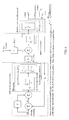
- FIG. 3 illustrates a servo system 100 including a feedback mechanism 102 (block H) that receives information about motion or position, and converts the information into a signal that can be subtracted from an input forcing function x i 104.
- x i forcing function 104 is the control signal or digital command that directs the entire servo system to respond, such that a mechanical output y o 106 moves in an intended way.
- a plurality of blocks 108 represent various parts of the servo system structure such as data processed in a computer, an electrical motor, and a mechanism that converts rotation of the motor shaft into a useful motion or position of the device.
- a signal x 2 represents a load function 110, e.g., a parameter such as friction or other mechanical loading that tends to resist movement driven by a motor shaft.
- a monitor point 112 (M) provides data to the system that represents the difference between x i forcing function 104 and a feedback signal 114 that has passed through H feedback block 102.
- M The value of M is generally small (depending on the many parameters that define servo system 100). However, M may temporarily have larger values when servo system 100 is being subjected to certain types of stimulus transients that are applied to either x i or x 2 . By proper interpretation of M, it is possible to determine if servo system 100 has encountered a (undesired) collision-in-progress. Under this condition servo system 100 performance can be altered to avoid the unwanted result of a collision from a fully executed movement. Feed forward through a block F 1 116 allows special processing of the x i forcing function to achieve an enhanced detectability to collisions at M 112. Note that F 1 could be summed into the system at points other than that shown in Figure 3, with variations in the results.
- monitor point M 112 can be placed at locations other than that shown in Figure 3, with variations in the results.
- multiple points for injecting feedback (114) could be used, in addition to those points shown in Figure 3. Depending on characteristics of any system, the placement of feed forward injection, the monitoring point, and feedback may vary.
- G 1 can be chosen to make y o /x 2 behave optimally for collision detection and avoidance.
- G 1 and F 1 but not G 1 '
- a feed forward term F 1 in the servo system enables it to be optimized for both y o /x i and y o /x 2, , such that collision detection monitoring at M is enhanced without compromising responsiveness to the forcing function x i .
- injecting a feed forward term to optimize y o /x i allows for the separate and independent optimizing of y o /x 2 via the standard existing loop parameters without the influence of feed forward.
- Figure 4 illustrates a specific example of an electromechanical servos system shown generically in Figure 3.
- the closed loop response for Figure 4 inputs x i and x 2 are given
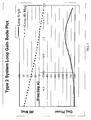
- the loop gain Bode plot that is optimized for x i is given in Figure 5 with associated optimized parameters listed in Table 1.
- the loop gain Bode plot in Figure 5 was optimized for x i using K 5 ' and Z 5 '. Because of the feed forward parameter F (equation 10), this plot's phase margin can be used to predict the transient response of y o /x i . Note that for true stability, a Bode plot using K 5 and Z 5 (not K 5 ' and Z 5 ') can be used.
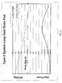
- the loop gain Bode plot that is optimized for x 2 is given in Figure 6 with associated optimized parameters listed in Table 2.
- the plot was optimized for x 2 using K 5 and Z 5 . Note, the plots margins can be used to predict the transient response of y o /x 2 .
- FIG 7 the simulated response output, y o , is shown for a step response input from x i (forcing function to command the mechanism to move) for the topology of Figure 4. Also shown in Figure 7 are the monitor point signals, M, for a step at x 2 (representing a collision) that would occur with and without using feed forward.
- the peak M monitor signal is larger when feed forward is applied, having a ratio of about 2.4.
- the plot for M/x 2 also represents the plot for y o /x 2 (except for polarity). It is noted that M/x 2 with feed forward changes more quickly than M/x 2 without feed forward. This indicates that y o would also change more quickly, and that y o would therefore be more responsive to the collision signal x 2 . With proper use of feed forward, the servo system would therefore not be as aggressive in powering motion through the collision, even before the M monitor point signal has been processed as a means to detect collision (and initiate a command to stop motion).
- FIG 8 the simulated response output, y o , is shown for a step response input from x i, and is identical to the simulation for y o shown in Figure 7. Also shown in Figure 8 are the monitor point signals, M, that would occur with and without using feed forward for a 20 msec pulse at x 2 (representing a bump that might occur when an imperfect mechanism is in motion). In this case the ratio for the peak M monitor signal with and without feed forward is about 1.4. Note, the pulse is amplified in the plot so it can be seen, due to the units used in Figure 8.
- the example servo system when stimulated as described, can detect a smaller legitimate collision without also being subject to false alarms from a bump due to an imperfect mechanism. Therefore one technical effect is the enhanced sensitivity to collision stimulus. Because of the enhanced sensitivity to collision stimulus, the detection threshold at M could be increased. Then the servo system is less likely to generate a false alarm from a monitor signal that results from the x i forcing function.
Landscapes
- Health & Medical Sciences (AREA)
- Life Sciences & Earth Sciences (AREA)
- Medical Informatics (AREA)
- Engineering & Computer Science (AREA)
- Radiology & Medical Imaging (AREA)
- Molecular Biology (AREA)
- Biophysics (AREA)
- Nuclear Medicine, Radiotherapy & Molecular Imaging (AREA)
- Optics & Photonics (AREA)
- Pathology (AREA)
- Physics & Mathematics (AREA)
- Biomedical Technology (AREA)
- Heart & Thoracic Surgery (AREA)
- High Energy & Nuclear Physics (AREA)
- Surgery (AREA)
- Animal Behavior & Ethology (AREA)
- General Health & Medical Sciences (AREA)
- Public Health (AREA)
- Veterinary Medicine (AREA)
- Feedback Control In General (AREA)
- Apparatus For Radiation Diagnosis (AREA)
- Control Of Electric Motors In General (AREA)
Applications Claiming Priority (2)
| Application Number | Priority Date | Filing Date | Title |
|---|---|---|---|
| US10/695,179 US7034492B2 (en) | 2003-10-28 | 2003-10-28 | Methods and systems for reducing unintentional collisions |
| US695179 | 2003-10-28 |
Publications (1)
| Publication Number | Publication Date |
|---|---|
| EP1527738A1 true EP1527738A1 (de) | 2005-05-04 |
Family
ID=34423350
Family Applications (1)
| Application Number | Title | Priority Date | Filing Date |
|---|---|---|---|
| EP04256513A Withdrawn EP1527738A1 (de) | 2003-10-28 | 2004-10-22 | Verfahren und Gerät zur Reduzierung unabsichtlicher Kollisionen in medizinischen Bilderzeugungssystemen |
Country Status (5)
| Country | Link |
|---|---|
| US (2) | US7034492B2 (de) |
| EP (1) | EP1527738A1 (de) |
| JP (1) | JP4831558B2 (de) |
| KR (1) | KR101084387B1 (de) |
| CN (1) | CN1612038B (de) |
Cited By (2)
| Publication number | Priority date | Publication date | Assignee | Title |
|---|---|---|---|---|
| DE102005049106A1 (de) * | 2005-10-13 | 2007-04-19 | Siemens Ag | Medizinisches Bildgebungssystem und Kollisionsschutzverfahren mit regelbarem Arm |
| EP2502563B1 (de) * | 2011-03-24 | 2017-06-21 | General Electric Company | Multiplanes System für medizinische Bildgebung |
Families Citing this family (11)
| Publication number | Priority date | Publication date | Assignee | Title |
|---|---|---|---|---|
| US7029175B2 (en) * | 2003-05-19 | 2006-04-18 | Ge Medical Systems Global Technology Company, Llc | Method and apparatus for object collision detection utilizing a PID controller in a motorized, mobile C-arm |
| US7034492B2 (en) * | 2003-10-28 | 2006-04-25 | Ge Medical Systems Global Technology Company, Llc | Methods and systems for reducing unintentional collisions |
| US7609813B2 (en) * | 2006-11-08 | 2009-10-27 | General Electric Company | System and method for improved collision detection in an imaging device |
| ES2659090T3 (es) | 2009-03-20 | 2018-03-13 | Orthoscan Incorporated | Aparato móvil de captación de imagen |
| DE102009037316A1 (de) * | 2009-08-14 | 2011-02-17 | Karl Storz Gmbh & Co. Kg | Steuerung und Verfahren zum Betreiben einer Operationsleuchte |
| US8534268B2 (en) * | 2009-09-14 | 2013-09-17 | Nagesh Mavinahally | Two-stroke engine |
| WO2012082799A1 (en) | 2010-12-13 | 2012-06-21 | Orthoscan, Inc. | Mobile fluoroscopic imaging system |
| JP6469336B2 (ja) * | 2013-02-12 | 2019-02-13 | キヤノンメディカルシステムズ株式会社 | X線診断装置、及びx線診断装置の制御方法 |
| WO2014192960A1 (ja) * | 2013-05-31 | 2014-12-04 | 株式会社 東芝 | X線診断装置 |
| US10828120B2 (en) | 2014-06-19 | 2020-11-10 | Kb Medical, Sa | Systems and methods for performing minimally invasive surgery |
| US10299740B2 (en) * | 2015-09-29 | 2019-05-28 | General Electric Company | Methods and systems for cone-beam computed tomography |
Citations (4)
| Publication number | Priority date | Publication date | Assignee | Title |
|---|---|---|---|---|
| US4211927A (en) * | 1978-11-24 | 1980-07-08 | Cgr Medical Corporation | Computerized tomography system |
| US4345194A (en) * | 1980-12-01 | 1982-08-17 | The United States Of America As Represented By The United States Department Of Energy | Control system to reduce the effects of friction in drive trains of continuous-path-positioning systems |
| EP0556412A1 (de) * | 1991-09-09 | 1993-08-25 | Fanuc Ltd. | Verfahren zur steuerung eines servomotors mit vorwärtskopplung |
| US5710496A (en) * | 1994-09-01 | 1998-01-20 | U.S. Philips Corporation | Drive including PID position feedback drive and control system fed by speed control unit and X-ray device comprising such a drive |
Family Cites Families (20)
| Publication number | Priority date | Publication date | Assignee | Title |
|---|---|---|---|---|
| JPS5030915B1 (de) * | 1969-08-30 | 1975-10-04 | ||
| FR2580827B1 (fr) * | 1985-04-19 | 1987-05-22 | Thomson Cgr | Installation de radiologie |
| US4893068A (en) * | 1988-11-15 | 1990-01-09 | Hughes Aircraft Company | Digital servo employing switch mode lead/lag integrator |
| JPH02184281A (ja) * | 1989-01-10 | 1990-07-18 | Fanuc Ltd | 誤差過大アラーム発生方法 |
| US5304906A (en) * | 1989-12-26 | 1994-04-19 | Fanuc Ltd. | Collision detecting method using an observer |
| JP3271794B2 (ja) * | 1992-05-07 | 2002-04-08 | 株式会社日立メディコ | X線ct装置 |
| DE69327436T2 (de) * | 1992-09-14 | 2000-08-03 | Koninklijke Philips Electronics N.V., Eindhoven | Gerät, insbesondere zur Röntgen-Untersuchung, mit Anordnung zum Kollisionsschutz |
| KR970055208A (ko) * | 1995-12-28 | 1997-07-31 | 김광호 | 서보모터의 속도제어방법 및 속도제어장치 |
| JP3291224B2 (ja) * | 1997-06-30 | 2002-06-10 | オークマ株式会社 | 速度制御装置 |
| JP3201337B2 (ja) * | 1998-03-27 | 2001-08-20 | 双葉電子工業株式会社 | 移動体の操縦装置 |
| JP2002521107A (ja) * | 1998-07-23 | 2002-07-16 | コーニンクレッカ フィリップス エレクトロニクス エヌ ヴィ | 高解像度画像センサを備えたx線検査装置 |
| JP3212571B2 (ja) * | 1999-03-26 | 2001-09-25 | ファナック株式会社 | 産業用ロボット |
| US6285438B1 (en) * | 1999-05-19 | 2001-09-04 | Nikon Corporation | Scanning exposure method with reduced time between scans |
| WO2001039558A1 (en) * | 1999-11-23 | 2001-05-31 | Koninklijke Philips Electronics N.V. | X-ray examination apparatus with exposure control |
| DE60135586D1 (de) * | 2000-05-15 | 2008-10-09 | Yaskawa Denki Kitakyushu Kk | Positionerungs-Servosteuerung |
| JP4700798B2 (ja) * | 2000-10-25 | 2011-06-15 | ジーイー・メディカル・システムズ・グローバル・テクノロジー・カンパニー・エルエルシー | X線ct装置 |
| JP2002199767A (ja) * | 2000-12-27 | 2002-07-12 | Aisin Seiki Co Ltd | 外乱補償制御装置 |
| US6507638B2 (en) * | 2001-05-30 | 2003-01-14 | Ge Medical Systems Global Technology Company Llc | X-ray imaging optical camera apparatus and method of use |
| US6668202B2 (en) * | 2001-11-21 | 2003-12-23 | Sumitomo Heavy Industries, Ltd. | Position control system and velocity control system for stage driving mechanism |
| US7034492B2 (en) * | 2003-10-28 | 2006-04-25 | Ge Medical Systems Global Technology Company, Llc | Methods and systems for reducing unintentional collisions |
-
2003
- 2003-10-28 US US10/695,179 patent/US7034492B2/en not_active Expired - Lifetime
-
2004
- 2004-10-22 EP EP04256513A patent/EP1527738A1/de not_active Withdrawn
- 2004-10-27 KR KR1020040086278A patent/KR101084387B1/ko not_active Expired - Fee Related
- 2004-10-27 JP JP2004312175A patent/JP4831558B2/ja not_active Expired - Fee Related
- 2004-10-28 CN CN2004100901998A patent/CN1612038B/zh not_active Expired - Fee Related
-
2005
- 2005-12-08 US US11/296,947 patent/US7368888B2/en not_active Expired - Lifetime
Patent Citations (4)
| Publication number | Priority date | Publication date | Assignee | Title |
|---|---|---|---|---|
| US4211927A (en) * | 1978-11-24 | 1980-07-08 | Cgr Medical Corporation | Computerized tomography system |
| US4345194A (en) * | 1980-12-01 | 1982-08-17 | The United States Of America As Represented By The United States Department Of Energy | Control system to reduce the effects of friction in drive trains of continuous-path-positioning systems |
| EP0556412A1 (de) * | 1991-09-09 | 1993-08-25 | Fanuc Ltd. | Verfahren zur steuerung eines servomotors mit vorwärtskopplung |
| US5710496A (en) * | 1994-09-01 | 1998-01-20 | U.S. Philips Corporation | Drive including PID position feedback drive and control system fed by speed control unit and X-ray device comprising such a drive |
Cited By (3)
| Publication number | Priority date | Publication date | Assignee | Title |
|---|---|---|---|---|
| DE102005049106A1 (de) * | 2005-10-13 | 2007-04-19 | Siemens Ag | Medizinisches Bildgebungssystem und Kollisionsschutzverfahren mit regelbarem Arm |
| US8767920B2 (en) | 2005-10-13 | 2014-07-01 | Siemens Aktiengesellschaft | Medical imaging system and anti-collision method with a controllable arm |
| EP2502563B1 (de) * | 2011-03-24 | 2017-06-21 | General Electric Company | Multiplanes System für medizinische Bildgebung |
Also Published As
| Publication number | Publication date |
|---|---|
| CN1612038A (zh) | 2005-05-04 |
| KR20050040769A (ko) | 2005-05-03 |
| US7034492B2 (en) | 2006-04-25 |
| CN1612038B (zh) | 2011-05-18 |
| US7368888B2 (en) | 2008-05-06 |
| US20050088132A1 (en) | 2005-04-28 |
| US20060087274A1 (en) | 2006-04-27 |
| JP4831558B2 (ja) | 2011-12-07 |
| JP2005131395A (ja) | 2005-05-26 |
| KR101084387B1 (ko) | 2011-11-18 |
Similar Documents
| Publication | Publication Date | Title |
|---|---|---|
| CN107635465B (zh) | 抵衡x射线扫描仪台架的轴并且维持x射线扫描仪台架的用户选择位置的装置及方法 | |
| US7034492B2 (en) | Methods and systems for reducing unintentional collisions | |
| EP4072423B1 (de) | Sichtfeldanpassung für mobile 3d-bildgebung | |
| JP6139361B2 (ja) | 医用画像処理装置、治療システム及び医用画像処理方法 | |
| US10493298B2 (en) | Camera systems and methods for use in one or more areas in a medical facility | |
| CN104812304B (zh) | 用于断层融合移动射线照相装置的扫描几何校正 | |
| US6927395B2 (en) | Gamma camera collision avoidance | |
| CN103930031A (zh) | 针对x射线成像系统的定位距离控制 | |
| US20070211847A1 (en) | Method for recording projection data sets of an object under examination | |
| US12350076B2 (en) | Integrated computed tomography (CT) treatment couch system | |
| US7609813B2 (en) | System and method for improved collision detection in an imaging device | |
| JP2017124300A (ja) | 画像処理装置、治療システム及び画像処理方法 | |
| İncetan et al. | RGB-D camera-based clinical workflow optimization for rotational angiography | |
| Khatri et al. | Opportunities and challenges in medical robotic device development | |
| Kim et al. | Development of a medical robot system for pedicle screw surgery assisted by fluoroscopic X-ray image | |
| Donovan et al. | Accuracy and precision of an external-marker tracking-system for radiotherapy treatments | |
| Wong et al. | Respiratory motion compensation studies using a 3D robotic motion simulator and optical/electromagnetic tracking technologies | |
| Siddique et al. | Towards active image guidance: Tracking of a fiducial in the thorax during respiration under x-ray fluoroscopy |
Legal Events
| Date | Code | Title | Description |
|---|---|---|---|
| PUAI | Public reference made under article 153(3) epc to a published international application that has entered the european phase |
Free format text: ORIGINAL CODE: 0009012 |
|
| AK | Designated contracting states |
Kind code of ref document: A1 Designated state(s): AT BE BG CH CY CZ DE DK EE ES FI FR GB GR HU IE IT LI LU MC NL PL PT RO SE SI SK TR |
|
| AX | Request for extension of the european patent |
Extension state: AL HR LT LV MK |
|
| 17P | Request for examination filed |
Effective date: 20051104 |
|
| AKX | Designation fees paid |
Designated state(s): DE FR GB IT NL |
|
| 17Q | First examination report despatched |
Effective date: 20100129 |
|
| STAA | Information on the status of an ep patent application or granted ep patent |
Free format text: STATUS: THE APPLICATION IS DEEMED TO BE WITHDRAWN |
|
| 18D | Application deemed to be withdrawn |
Effective date: 20140423 |