EP1527835B1 - Spannfutter - Google Patents
Spannfutter Download PDFInfo
- Publication number
- EP1527835B1 EP1527835B1 EP04104395A EP04104395A EP1527835B1 EP 1527835 B1 EP1527835 B1 EP 1527835B1 EP 04104395 A EP04104395 A EP 04104395A EP 04104395 A EP04104395 A EP 04104395A EP 1527835 B1 EP1527835 B1 EP 1527835B1
- Authority
- EP
- European Patent Office
- Prior art keywords
- sleeve
- chuck
- flange
- clamp
- thrust
- Prior art date
- Legal status (The legal status is an assumption and is not a legal conclusion. Google has not performed a legal analysis and makes no representation as to the accuracy of the status listed.)
- Expired - Lifetime
Links
- 230000007423 decrease Effects 0.000 claims abstract description 13
- 238000003780 insertion Methods 0.000 claims description 2
- 230000037431 insertion Effects 0.000 claims description 2
- 238000007789 sealing Methods 0.000 description 8
- 230000005489 elastic deformation Effects 0.000 description 6
- 238000005520 cutting process Methods 0.000 description 5
- 230000000694 effects Effects 0.000 description 5
- 238000003754 machining Methods 0.000 description 4
- 230000002411 adverse Effects 0.000 description 2
- ATJFFYVFTNAWJD-UHFFFAOYSA-N Tin Chemical compound [Sn] ATJFFYVFTNAWJD-UHFFFAOYSA-N 0.000 description 1
- 239000011248 coating agent Substances 0.000 description 1
- 238000000576 coating method Methods 0.000 description 1
- 230000002349 favourable effect Effects 0.000 description 1
- 238000012986 modification Methods 0.000 description 1
- 230000004048 modification Effects 0.000 description 1
- 230000002265 prevention Effects 0.000 description 1
Images




Classifications
-
- B—PERFORMING OPERATIONS; TRANSPORTING
- B23—MACHINE TOOLS; METAL-WORKING NOT OTHERWISE PROVIDED FOR
- B23B—TURNING; BORING
- B23B31/00—Chucks; Expansion mandrels; Adaptations thereof for remote control
- B23B31/02—Chucks
- B23B31/10—Chucks characterised by the retaining or gripping devices or their immediate operating means
- B23B31/117—Retention by friction only, e.g. using springs, resilient sleeves, tapers
-
- B—PERFORMING OPERATIONS; TRANSPORTING
- B23—MACHINE TOOLS; METAL-WORKING NOT OTHERWISE PROVIDED FOR
- B23B—TURNING; BORING
- B23B2231/00—Details of chucks, toolholder shanks or tool shanks
- B23B2231/14—Chucks with clamping force limitation means
-
- Y—GENERAL TAGGING OF NEW TECHNOLOGICAL DEVELOPMENTS; GENERAL TAGGING OF CROSS-SECTIONAL TECHNOLOGIES SPANNING OVER SEVERAL SECTIONS OF THE IPC; TECHNICAL SUBJECTS COVERED BY FORMER USPC CROSS-REFERENCE ART COLLECTIONS [XRACs] AND DIGESTS
- Y10—TECHNICAL SUBJECTS COVERED BY FORMER USPC
- Y10S—TECHNICAL SUBJECTS COVERED BY FORMER USPC CROSS-REFERENCE ART COLLECTIONS [XRACs] AND DIGESTS
- Y10S279/00—Chucks or sockets
- Y10S279/903—Needle roller type socket
-
- Y—GENERAL TAGGING OF NEW TECHNOLOGICAL DEVELOPMENTS; GENERAL TAGGING OF CROSS-SECTIONAL TECHNOLOGIES SPANNING OVER SEVERAL SECTIONS OF THE IPC; TECHNICAL SUBJECTS COVERED BY FORMER USPC CROSS-REFERENCE ART COLLECTIONS [XRACs] AND DIGESTS
- Y10—TECHNICAL SUBJECTS COVERED BY FORMER USPC
- Y10T—TECHNICAL SUBJECTS COVERED BY FORMER US CLASSIFICATION
- Y10T279/00—Chucks or sockets
- Y10T279/17—Socket type
-
- Y—GENERAL TAGGING OF NEW TECHNOLOGICAL DEVELOPMENTS; GENERAL TAGGING OF CROSS-SECTIONAL TECHNOLOGIES SPANNING OVER SEVERAL SECTIONS OF THE IPC; TECHNICAL SUBJECTS COVERED BY FORMER USPC CROSS-REFERENCE ART COLLECTIONS [XRACs] AND DIGESTS
- Y10—TECHNICAL SUBJECTS COVERED BY FORMER USPC
- Y10T—TECHNICAL SUBJECTS COVERED BY FORMER US CLASSIFICATION
- Y10T279/00—Chucks or sockets
- Y10T279/17—Socket type
- Y10T279/17957—Friction grip
-
- Y—GENERAL TAGGING OF NEW TECHNOLOGICAL DEVELOPMENTS; GENERAL TAGGING OF CROSS-SECTIONAL TECHNOLOGIES SPANNING OVER SEVERAL SECTIONS OF THE IPC; TECHNICAL SUBJECTS COVERED BY FORMER USPC CROSS-REFERENCE ART COLLECTIONS [XRACs] AND DIGESTS
- Y10—TECHNICAL SUBJECTS COVERED BY FORMER USPC
- Y10T—TECHNICAL SUBJECTS COVERED BY FORMER US CLASSIFICATION
- Y10T279/00—Chucks or sockets
- Y10T279/17—Socket type
- Y10T279/17957—Friction grip
- Y10T279/17965—Drill type
Definitions
- the present invention relates to chucks for chucking a cutting tool such as a drill or end mill, and more particularly to chucks in which a clamp sleeve is fitted onto the outer circumference of a chuck sleeve of a holder body via needle rollers and in which, through rotation of the clamp sleeve in a clamping direction, the diameter of the chuck sleeve is reduced in order to tightly chuck a desired tool.
- a chuck according to the preamble of claim 1 is for example known from JP10263908 .
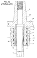
- the tool chuck has a holder body 1.
- the tool holder body 1 has a tapered shank portion 1A to be inserted into a spindle of a machine tool (not shown), a gripping flange 1B formed at the larger-diameter end of the tapered shank portion 1A, and a chuck sleeve 1C that extends from the end surface of the flange 1B opposite the tapered shank portion 1A.
- the chuck sleeve 1C extends in the direction away from the tapered shank portion 1A such that the axis of the chuck sleeve 1C coincides with the axis of the tapered shank portion 1A.
- a tapered surface 1Ca is formed on the outer circumference of the chuck sleeve 1C such that the diameter of the surface 1Ca decreases toward the tip end thereof.
- Reference numeral 2 denotes a roller-retaining sleeve which is fitted onto the outer circumference of the chuck sleeve 1C with a clearance therebetween.
- the diameter of the roller-retaining sleeve 2 decreases toward the tip end thereof substantially at the same rate as that of the tapered surface 1Ca of the chuck sleeve 1C.
- the roller-retaining sleeve 2 is held by a retainer ring 3 provided on the outer circumference of the tip end portion of the chuck sleeve 1C such that the roller-retaining sleeve 2 is prevented from coming off the chuck sleeve 1C.
- roller-retaining sleeve 2 In the roller-retaining sleeve 2, numerous needle rollers 4 are disposed to form a plurality of rows.
- the needle rollers are fitted into the roller-retaining sleeve 2 in such a manner that the needle rollers incline in the circumferential direction at a predetermined angle with respect to the centre axis of the roller-retaining sleeve 2.
- Each of the needle rollers 4 has a diameter greater than the wall thickness of the roller-retaining sleeve 2, so that the portion of each needle roller 4 projecting inward from the inner circumferential surface of the roller retaining sleeve 2 is in contact with the tapered surface 1Ca of the chuck sleeve 1C, while the portion of each needle roller 4 projecting outward from the outer circumferential surface of the roller retaining-sleeve 2 is in contact with the inner circumferential surface of a clamp sleeve 5, which will be described below.
- the clamp sleeve 5 is adapted to reduce the diameter of the chuck sleeve 1C thereby to tightly chuck a desired tool.
- the clamp sleeve 5 is fitted onto the outer circumference of the chuck sleeve 1C via the needle rollers 4 held by the roller-retaining sleeve 2.
- the clamp sleeve 5 has a tapered inner circumferential surface whose diameter decreases from the end facing the flange 1B toward the tip end thereof. Further, a sealing/retaining ring 6 is attached to the inner circumference of the bottom end portion of the clamp sleeve 5 adjacent to the flange 1B.
- the sealing/retaining ring 6 is in contact with the outer circumferential surface of the chuck sleeve 1C so as to provide a sealing function.
- the sealing/retaining ring 6 also abuts the end surface of the roller retaining sleeve 2 in order to prevent the clamp sleeve 5 from coming off the chuck sleeve 1C.
- the roller-retaining sleeve 2 moves toward the flange 1B, while rotating, in accordance with the revolution of the needle rollers 4, and at the same time the clamp sleeve 5 also moves toward the flange 1B.
- the movements of the roller-retaining sleeve 2 and the clamp sleeve 5 toward the flange 1B reduce the clearance between the tapered inner surface of the clamp sleeve 5 and the tapered outer surface of the chuck sleeve 1C, so that the clamp sleeve 5 strongly presses the chuck sleeve 1C from the entire outer circumference thereof via the needle rollers 4 in order to reduce the diameter of the chuck sleeve 1C.
- the shank 7A of the tool 7 inserted into the cylindrical bore of the chuck sleeve 1C is clamped and held by the chuck sleeve 1C via the spring collet 8.
- the roller-retaining sleeve 2 moves toward the tip end of the chuck sleeve 1C, and the clamp sleeve 5 also moves in the same direction. Therefore, the diameter of the chuck sleeve 1C is restored to its original size, so that the clamping force applied to the tool 7 is released. This enables the tool 7 to be removed from the chuck sleeve 1C or to be replaced with a different tool.
- the chuck sleeve 1C extends from the end surface of the flange 1B opposite the tapered shank portion 1A. Therefore, within an area of the tapered surface 1Ca adjacent to the base portion of the chuck sleeve 1C continuous with the flange 1B, the rigidity against elastic deformation in the radial direction is considerably higher than that in the remaining area. Therefore, when the clamp sleeve 5 is rotated in the clamping direction so as to reduce the diameter of the chuck sleeve 1C, within the above-described area of the tapered surface 1Ca the ratio of reduction in diameter is very small as compared to that in the remaining area.
- a groove having a predetermined depth is formed in the end surface of the flange opposite the shank portion such that the groove extends along the outer circumference of the bottom end of the chuck sleeve through which the chuck sleeve is joined with the flange.
- the groove increases the effective chucking length of the chuck sleeve; i.e., the length of a portion of the chuck sleeve in which the chuck sleeve can elastically deform in a diameter-reducing direction
- elastic deformation of the chuck sleeve in the diameter-reducing direction easily occurs over substantially the entire length of the chuck sleeve. Therefore, the effective chucking length of the chuck sleeve can be increased with no accompanying increase in the overall length of the chuck sleeve.
- the change ratio of the inner diameter of the chuck sleeve can be increased to some extent when the clamp sleeve 5 disposed to surround the outer circumferential surface of the chuck sleeve 1C is tightened to a degree such that the end surface of the clamp sleeve 5 abuts the end surface of the flange 1B opposite the tapered shank portion 1A.
- the tightening force becomes excessive, whereby the chuck sleeve 1C deforms because of torsion effects.
- Preferred embodiments of the present invention aim to solve the above-mentioned problems, and an object thereof is to provide a chuck which can prevent torsional deformation of a chuck sleeve, which would otherwise occur because of excessive tightening of a clamp sleeve against the chuck sleeve, thereby to eliminate adverse effects of the torsional deformation on the chuck sleeve, which in turn prevents deflective vibration in the chuck sleeve, which is a portion of a tool holder, thereby to improve machining accuracy.
- a chuck comprising: a holder body having a shank portion for insertion into a spindle of a machine tool, a gripping flange formed at one end of the shank portion, and a chuck sleeve that extends from the flange in a direction away from the shank portion in alignment with an axis of the shank portion, the chuck sleeve having a tapered outer circumferential surface whose diameter decreases from a bottom end adjacent to the flange to a tip end of the chuck sleeve; a clamp sleeve fitted onto the outer circumference surface of the chuck sleeve such that the clamp sleeve is rotatable and axially movable relative to the chuck sleeve, the clamp sleeve having a tapered inner circumferential surface whose diameter decreases from a bottom end adjacent to the flange toward a tip end of the clamp sleeve; and needle roller
- said groove extends along the outer circumference of the bottom end of the chuck sleeve through which the chuck sleeve is joined with the flange.
- a radially outer portion of the corresponding end surface of the clamp sleeve is raised so as to abut a radially outer portion of the thrust member.
- At least one of opposite surfaces of the thrust member is surface treated so as to reduce friction resistance produced when the end surface of the clamp sleeve comes into contact with the thrust member.
- the thrust member can prevent deformation, such as torsional deformation, of the chuck sleeve, which would otherwise occur because of excessive tightening of the clamp sleeve against the chuck sleeve, thereby to prevent adverse effects of the torsional deformation on the chuck sleeve, which in turn prevents deflective vibration in the chuck sleeve, which is a portion of a tool holder, thereby to improve machining accuracy.
- deformation such as torsional deformation
- the chuck sleeve can be extended toward the flange side with no accompanying increase in the overall length of the holder body.
- the radially inward elastic deformation of the chuck sleeve in a bottom end area adjacent to the flange can be made substantially equal to that in the remaining area.
- the effective chucking length of the chuck sleeve over which the chuck sleeve can elastically deform in the diameter-reducing direction can be increased without an increase in the overall length of the holder body.
- elastic deformation of the chuck sleeve in the diameter-reducing direction occurs more easily, thereby allowing an operator to tighten the clamp sleeve with ease until the end surface of the clamp sleeve abuts the flange of the holder body, without need of a large tightening force.
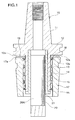
- Figures 1 to 5 show features that are part of embodiments of the invention, although the chucks of Figures 1 to 5 are not covered by the claims.
- the tool chuck has a holder body 10, which has a tapered shank portion 11 to be inserted into a spindle of a machine tool (not shown), a gripping flange 12 formed at the larger-diameter end of the tapered shank portion 11, and a chuck sleeve 13 that extends from an end surface 12a of the flange 12 opposite the tapered shank portion 11.
- the chuck sleeve 13 extends in the direction away from the tapered shank portion 11 such that the axis of the chuck sleeve 13 coincides with the axis of the tapered shank portion 11.
- the chuck sleeve 13 has a tapered outer circumferential surface 13a whose diameter decreases from the bottom end adjacent to the flange 12 toward the tip end.
- Reference numeral 14 denotes a roller-retaining sleeve fitted onto the outer circumference of the chuck sleeve 13 with a clearance therebetween.
- the diameter of the roller retaining sleeve 14 decreases toward the tip end thereof at the same rate as that of the tapered surface 13a of the chuck sleeve 13.
- the roller-retaining sleeve 14 is held by a retainer ring 15 provided on the outer circumference of the tip end portion of the chuck sleeve 13 such that the roller-retaining sleeve 14 is prevented from coming off the chuck sleeve 13.
- roller-retaining sleeve 14 In the roller-retaining sleeve 14, numerous needle rollers 16 are arranged in the circumferential direction to form a plurality of rows in the longitudinal direction.
- the needle rollers 16 are fitted into the roller-retaining sleeve 14 in such a manner that the needle rollers 16 incline in the circumferential direction at a predetermined angle with respect to the centre axis of the roller retaining sleeve 14.
- Each of the needle rollers 16 has a diameter greater than the wall thickness of the roller-retaining sleeve 14, so that the portion of each needle roller 16 projecting inward from the inner circumferential surface of the roller-retaining sleeve 14 is in contact with the tapered surface 13a of the chuck sleeve 13, while the portion of each needle roller 16 projecting outward from the outer circumferential surface of the roller retaining sleeve 14 is in contact with the inner circumferential surface of a clamp sleeve 17, which will be described below.
- the clamp sleeve 17 is adapted to reduce the diameter of the chuck sleeve 13 thereby to tightly chuck a desired tool.
- the clamp sleeve 17 is fitted onto the outer circumference of the chuck sleeve 13 via the needle rollers 16 held by the roller-retaining sleeve 14.
- the clamp sleeve 17 has a tapered inner circumferential surface whose diameter decreases from the end facing the flange 12 toward the tip end thereof.
- a sealing/retaining ring 18 is attached to the inner circumference of the bottom end portion of the clamp sleeve 17 adjacent to the flange 12.
- the sealing/retaining ring 18 is in contact with the outer circumferential surface of the chuck sleeve 13 so as to provide a sealing function.
- the sealing/retaining ring 18 also abuts the end surface of the roller-retaining sleeve 14 in order to prevent the clamp sleeve 17 from coming off the chuck sleeve 13.
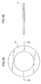
- Reference numeral 19 denotes a thrust member, which assumes a flat annular shape and has a circular central opening, as shown in Figures 3A and 3B.
- the thrust member 19 is disposed between the end surface 12a of the gripping flange 12 opposite the tapered shank portion and a corresponding end surface 17a of the clamp sleeve 17, which is attached to the chuck sleeve 13.
- At least one of the opposite surfaces of the thrust member 19 (preferably, both the opposite surfaces of the thrust member 19) is surface treated by means of, for example, TiN coating, in order to reduce the coefficient of friction of the surface.
- the roller-retaining sleeve 14 moves toward the flange 12, while rotating, in accordance with the revolution of the needle rollers 16, and at the same time the clamp sleeve 17 also moves toward the flange 12.
- the movements of the roller-retaining sleeve 14 and the clamp sleeve 17 toward the flange 12 reduce the clearance between the tapered inner surface of the clamp sleeve 17 and the tapered outer surface of the chuck sleeve 13, so that the clamp sleeve 17 strongly presses the chuck sleeve 13 from the entire outer circumference thereof via the needle rollers 16 in order to reduce the diameter of the chuck sleeve 13.
- the shank 20A of the tool 20 inserted into the cylindrical bore of the chuck sleeve 13 is clamped and held by the chuck sleeve 13 via the spring collet 21 (see Figure 2).
- one end surface of the thrust member 19 abuts the end surface 17a of the clamp sleeve 17, and the other end surface of the thrust member 19 abuts the end surface 12a of the flange 12, whereby the end surface 17a of the clamp sleeve 17 abuts the end surface 12a of the flange 12 via the thrust member 19.
- an excessive clamp force may be applied.
- the end surface 17a of the clamp sleeve 17 then slides on the surface of the thrust member 19, thereby to prevent deformation, such as torsional deformation, of the clamp sleeve 17.
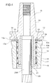
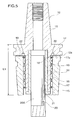
- the chuck shown in Figures 4 and 5 is identical with that previously shown and described, except that in the end surface 12a of the flange 12 opposite the tapered shank portion, a groove 22 having a predetermined depth (approximately 2 to 5 mm) is formed, at the bottom portion of the chuck sleeve 13 through which the chuck sleeve 13 is joined with the flange 12, such that the groove 22 extends along the outer circumference of the chuck sleeve 13 to form a ring-like shape.
- the ring-shaped groove 22 allows the chuck sleeve 13 to be extended toward the flange 12 side without changing the tool length L1 of the holder body 10.
- the radially inward elastic deformation of the chuck sleeve 13 in a bottom end area adjacent to the flange 12 is made substantially equal to that in the remaining area of the chuck sleeve 13.
- the chuck of Figures 4 and 5 has the same deformation prevention function as that of the chuck of Figures 1 to 3. That is, even when an excessive clamp force is applied because of a tightening operation continued after abutment, deformation, such as torsional deformation, of the clamp sleeve 17 can be prevented, because the end surface 17a of the clamp sleeve 17 slides on the surface of the thrust member 19.
- the clamp sleeve 17 can be tightened with ease until the end surface 17a of the clamp sleeve 17 abuts the end surface 12a of the flange, without need of large tightening force, whereby a sufficiently large chucking force can be applied to the tool shank 20A in an area corresponding to the bottom end of the chuck sleeve 13 through which the chuck sleeve 13 is joined with the flange 12.
- the radially inward elastic deformation of the chuck sleeve 13 in a bottom end area adjacent to the flange 12 can be made substantially equal to that in the remaining area.
- this structure can prevent rubbing between the outer circumferential surface of the tool shank 20A and the inner wall surface of the chuck sleeve 13, thereby to prevent damage to the outer circumferential surface of the tool shank 20A and the inner wall surface of the chuck sleeve 13.
- the feature of the chuck according to Figures 6 to 8 resides in that the annular groove 22 is formed in the end surface of the flange 12 in order to increase the effective length of the chuck sleeve 13, and that a thrust-member holder 23 is provided in order to prevent play or movement of the thrust member 19 along the axial direction.
- the thrust-member holder 23 is fitted into the central opening of the thrust member 19.
- the thrust-member holder 23 has an opening for allowing passage of the chuck sleeve 13 therethrough, and a stepped portion 23a which projects outward from a first end of the thrust member holder 23 for engagement with the edge portion of the central opening of the thrust member 19.
- An elastic member 24, such as an O-ring, is fitted into a circumferential groove formed at a second end of the thrust-member holder 23. When the second end of the thrust-member holder 23 is fitted into the groove 22, the elastic member 24 engages with the wall surface of the groove 22 thereby to prevent axial movement of the thrust-member holder 23.
- the thrust member 19 in engagement with the stepped portion 23a of the thrust member holder 23 is prevented from playing or moving in the axial direction after tightening of the clamp sleeve 17.
- a radially outer portion of the end surface 17a of the clamp sleeve 17, which portion comes into contact with the thrust member 19, is raised in the axial direction so as to form a raised portion 17b.
- the raised portion 17b abuts a radially outer portion of the thrust member 19.
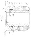
- the feature of the chuck according to Figures 9 to 11 resides in the shape of the chuck sleeve 13.
- the chuck sleeve 13 has a larger diameter portion 13b extending from the flange 12 in the direction opposite the shank portion, and a smaller diameter portion extending from the large diameter portion 13b via a stepped portion 13c.
- the clamp sleeve 17 is fitted onto the outer circumference of the smaller diameter portion of the chuck sleeve 13 via needle rollers 16.
- An annular groove 22 is formed in the stepped portion 13c in such a manner that an inner wall surface is substantially flush with the outer circumference of the smaller diameter portion of the chuck sleeve 13.
- the second end of the thrust-member holder 23 carrying the thrust member 19 is fitted into the groove 22.
- the outer circumferential surface of the larger diameter portion 13b of the chuck sleeve 13 is flush with the outer circumferential surface of the clamp sleeve 17.
Landscapes
- Engineering & Computer Science (AREA)
- Mechanical Engineering (AREA)
- Gripping On Spindles (AREA)
- Rolls And Other Rotary Bodies (AREA)
Claims (4)
- Ein Bohrfutter, umfassend:einen Haltekörper (10) mit einem Schaftabschnitt (11) zum Einführen in eine Spindel einer Werkzeugmaschine, einen an einem Ende des Schaftabschnitts (11) ausgebildeten Spannflansch (12) und eine Futterbuchse (13), welche sich von dem Flansch (12) in eine sich von dem Schaftabschnitt (11) entfernenden Richtung, fluchtend mit einer Achse des Schaftabschnitts (11) erstreckt, wobei die Futterbuchse (13) eine sich verjüngende äußere Umfangsfläche aufweist, deren Durchmesser von einem unteren Ende in der Nähe des Flansches (12) zu einem spitzen Ende der Futterbuchse (13) hin abnimmt;eine Spannbuchse (17), welche derart auf der äußeren Umfangsfläche der Futterbuchse (13) aufsitzt, daß die Spannbuchse (17) relativ zu der Futterbuchse (13) rotatorisch und axial beweglich ist, wobei die Spannbuchse (17) eine sich verjüngende innere Umfangsoberfläche aufweist, deren Durchmesser von einem unteren Ende in der Nähe des Flansches (12) zu einem spitzen Ende der Spannbuchse (17) hin abnimmt; undNadelrollen (16), welche zwischen der äußeren Umfangsfläche der Futterbuchse (13) und der inneren Umfangsfläche der Spannbuchse (17) über den gesamten Umfang angeordnet sind, wobei die Nadelrollen (16) in Umfangsrichtung um einen vorgegebenen Winkel gegenüber der Mittelachse der Futterbuchse (13) und der Spannbuchse (17) geneigt sind und wobei die Spannbuchse (17) gedreht wird, um zu bewirken, daß die Nadelrollen (16) spiralförmig um die äußere Umfangsoberfläche der Spannbuchse (13) laufen, während sie sich um ihre eigene Achse drehen, um den Durchmesser der Spannbuchse (13) zu verringern und wieder zu vergrößern; undein zwischen einer Endoberfläche (12a) des Flansches (12) gegenüber dem Schaftbereich (11) und einer korrespondierenden Endoberfläche (17a) der Spannbuchse (17) angeordnetes Druckstück (19),dadurch gekennzeichnet, daß das Druckstück (19) von Mitteln eines Druckstückhalters (23) gehalten wird, welche eine ringförmige flache Form aufweisen und welche in einem mittleren Bereich eine Öffnung aufweisen, die ein Durchdringen der Futterbuchse (13) ermöglicht, wobei ein Ende des Druckstückhalters (23) in einer ringförmigen Nut (22) angeordnet ist, wobei die ringförmige Nut (22) in der Endoberfläche des Flansches (12) ausgebildet ist und wobei der Druckstückhalter (23) ein elastisches Element umfaßt, welches am Ende des Druckstückhalters (23) in der Nut (22) angeordnet ist und mit einer Wandfläche der Nut (22) derart in Eingriff steht, daß die Beweglichkeit des Druckstückhalters (23) in axialer Richtung eingeschränkt ist.
- Bohrfutter nach Anspruch 1, wobei die Nut (22) sich entlang der äußeren Oberfläche des unteren Endes der Futterbuchse (13) erstreckt, durch welche die Futterbuchse (13) mit dem Flansch (12) verbunden ist, erstreckt.
- Bohrfutter nach Anspruch 1 oder 2, wobei ein radialer äußerer Bereich der korrespondierenden Endoberfläche (17a) der Spannbuchse (17) eine Erhöhung (17b) aufweist, so daß diese an einen radialen äußeren Bereich des Druckstücks (19) angrenzt.
- Bohrfutter nach Anspruch 1, 2 oder 3, wobei mindestens eine der gegenüberliegenden Oberflächen des Druckstücks (19) oberflächenbehandelt ist, so daß der Reibungswiderstand, welcher auftritt, wenn die Endoberfläche (17a) der Spannbuchse (17) in Kontakt mit dem Druckstück (19) kommt, reduziert ist.
Applications Claiming Priority (2)
| Application Number | Priority Date | Filing Date | Title |
|---|---|---|---|
| JP2003343333 | 2003-10-01 | ||
| JP2003343333A JP3997189B2 (ja) | 2003-10-01 | 2003-10-01 | チャック |
Publications (2)
| Publication Number | Publication Date |
|---|---|
| EP1527835A1 EP1527835A1 (de) | 2005-05-04 |
| EP1527835B1 true EP1527835B1 (de) | 2007-06-27 |
Family
ID=34386277
Family Applications (1)
| Application Number | Title | Priority Date | Filing Date |
|---|---|---|---|
| EP04104395A Expired - Lifetime EP1527835B1 (de) | 2003-10-01 | 2004-09-10 | Spannfutter |
Country Status (6)
| Country | Link |
|---|---|
| US (1) | US7017919B2 (de) |
| EP (1) | EP1527835B1 (de) |
| JP (1) | JP3997189B2 (de) |
| AT (1) | ATE365601T1 (de) |
| DE (1) | DE602004007213T2 (de) |
| ES (1) | ES2289439T3 (de) |
Families Citing this family (8)
| Publication number | Priority date | Publication date | Assignee | Title |
|---|---|---|---|---|
| US20020144575A1 (en) * | 1999-09-17 | 2002-10-10 | David Niven | Gripping or clamping mechanisms |
| US20050050707A1 (en) * | 2003-09-05 | 2005-03-10 | Scott Joshua Lynn | Tip tool |
| IL176592A (en) * | 2006-06-27 | 2010-05-17 | Hanoch Guy | Chuck having a rotatable securing mechanism |
| DE102007038789A1 (de) * | 2007-08-07 | 2009-02-12 | Hainbuch Gmbh Spannende Technik | Spannvorrichtung und Anordnung einer solchen Spannvorrichtung mit einer Spannzange |
| DE202009007821U1 (de) * | 2009-06-03 | 2009-10-08 | Klingelnberg Ag | Zahnradmaschine mit Vibrationsdämpfung |
| US20140251033A1 (en) * | 2013-03-11 | 2014-09-11 | Agilent Technologies, Inc. | Sample tube holder providing zero force insertion of sample tube |
| DE102013225472A1 (de) * | 2013-12-10 | 2015-06-11 | Komet Group Gmbh | Werkzeuganordnung |
| US20150273593A1 (en) * | 2014-03-27 | 2015-10-01 | Meiko Machine Co., Ltd. | Chuck With Separate Retainer Parts |
Family Cites Families (17)
| Publication number | Priority date | Publication date | Assignee | Title |
|---|---|---|---|---|
| US3523693A (en) * | 1967-06-21 | 1970-08-11 | Alfred Ernest Sykes | Holding device |
| JPS6116204U (ja) * | 1984-06-29 | 1986-01-30 | 大昭和精機株式会社 | コンビネ−シヨンロツクホルダ− |
| US4660840A (en) * | 1984-12-28 | 1987-04-28 | Mizoguchi Iron Works & Co., Ltd. | Needle-roller type chuck |
| US4721423A (en) * | 1986-10-07 | 1988-01-26 | Daishowa Seiki Kabushiki Kaisha | Chuck |
| JP2562883B2 (ja) * | 1986-12-29 | 1996-12-11 | エヌテイ−ツ−ル株式会社 | 保持具 |
| US5158408A (en) * | 1987-11-10 | 1992-10-27 | Nt Tool Corporation | Chuck device |
| US4865336A (en) * | 1988-06-03 | 1989-09-12 | Carboloy Inc. | Apparatus for securing a cutting tool in a tool holder and machine tools employing the same |
| JPH0253503A (ja) * | 1988-08-18 | 1990-02-22 | Daishowa Seiki Co Ltd | チャック |
| US5335922A (en) * | 1992-05-25 | 1994-08-09 | Miyuki Unate | Chuck |
| JP3563562B2 (ja) * | 1997-02-24 | 2004-09-08 | 株式会社日研工作所 | チャック |
| JPH10263908A (ja) * | 1997-03-25 | 1998-10-06 | Nikken Kosakusho:Kk | チャック |
| US6382888B2 (en) * | 1997-07-09 | 2002-05-07 | Harold D Cook | Vibration dampened spindle and tool holder assembly |
| US5975816A (en) * | 1997-07-09 | 1999-11-02 | Cook; Harold D. | Harmonic dampener for rotary tool holder |
| EP1038619B1 (de) * | 1999-03-19 | 2007-09-19 | Nikken Kosakusho Works, Ltd. | Werkzeughalter |
| JP3374102B2 (ja) * | 1999-05-21 | 2003-02-04 | 株式会社戸田精機 | チャック |
| US6109842A (en) * | 1999-08-03 | 2000-08-29 | Cook; Harold D. | Tool holder with harmonic dampening drive mechanism |
| JP3899324B2 (ja) * | 2003-02-24 | 2007-03-28 | 株式会社日研工作所 | 工具ホルダ |
-
2003
- 2003-10-01 JP JP2003343333A patent/JP3997189B2/ja not_active Expired - Lifetime
-
2004
- 2004-08-01 US US10/909,733 patent/US7017919B2/en not_active Expired - Lifetime
- 2004-09-10 ES ES04104395T patent/ES2289439T3/es not_active Expired - Lifetime
- 2004-09-10 EP EP04104395A patent/EP1527835B1/de not_active Expired - Lifetime
- 2004-09-10 DE DE602004007213T patent/DE602004007213T2/de not_active Expired - Lifetime
- 2004-09-10 AT AT04104395T patent/ATE365601T1/de not_active IP Right Cessation
Also Published As
| Publication number | Publication date |
|---|---|
| DE602004007213T2 (de) | 2008-02-28 |
| ES2289439T3 (es) | 2008-02-01 |
| ATE365601T1 (de) | 2007-07-15 |
| DE602004007213D1 (de) | 2007-08-09 |
| US7017919B2 (en) | 2006-03-28 |
| US20050073115A1 (en) | 2005-04-07 |
| JP3997189B2 (ja) | 2007-10-24 |
| EP1527835A1 (de) | 2005-05-04 |
| JP2005103730A (ja) | 2005-04-21 |
Similar Documents
| Publication | Publication Date | Title |
|---|---|---|
| EP0988910B1 (de) | Werkzeughalter | |
| JP5444579B2 (ja) | チャック装置 | |
| JPS5924407Y2 (ja) | チヤツク装置 | |
| US20070053758A1 (en) | Tool holder | |
| JPH0435297B2 (de) | ||
| US5314198A (en) | Collet chuck apparatus | |
| EP3202516B1 (de) | Spannfutterstruktur | |
| EP1527835A1 (de) | Spannfutter | |
| US6105974A (en) | Chuck | |
| US7357608B2 (en) | Rotary tapered tool holder | |
| US7186064B1 (en) | Rotary tapered tool holder with adapter sleeve | |
| US20060115337A1 (en) | Runout eliminating collet chuck | |
| US5158408A (en) | Chuck device | |
| JP4330277B2 (ja) | 回転型ガイドブッシュ | |
| JP4273377B2 (ja) | ドリルチャック及びチャック装置 | |
| JPH0623608A (ja) | 工具ホルダ | |
| JPH0144243Y2 (de) | ||
| CN114260736B (zh) | 薄壁台阶盖板用开口套及薄壁台阶盖板加工方法 | |
| JPH0767641B2 (ja) | 保持具 | |
| JPS61103708A (ja) | 保持具 | |
| JPH081763Y2 (ja) | チャック | |
| JP2024058977A (ja) | コレットチャック用締付けナット | |
| JPH0819908A (ja) | 外径コレットチャック | |
| JP2010264554A (ja) | コレット式工具ホルダ | |
| JP5251063B2 (ja) | 切削工具 |
Legal Events
| Date | Code | Title | Description |
|---|---|---|---|
| PUAI | Public reference made under article 153(3) epc to a published international application that has entered the european phase |
Free format text: ORIGINAL CODE: 0009012 |
|
| AK | Designated contracting states |
Kind code of ref document: A1 Designated state(s): AT BE BG CH CY CZ DE DK EE ES FI FR GB GR HU IE IT LI LU MC NL PL PT RO SE SI SK TR |
|
| AX | Request for extension of the european patent |
Extension state: AL HR LT LV MK |
|
| 17P | Request for examination filed |
Effective date: 20051104 |
|
| AKX | Designation fees paid |
Designated state(s): AT BE BG CH CY CZ DE DK EE ES FI FR GB GR HU IE IT LI LU MC NL PL PT RO SE SI SK TR |
|
| GRAP | Despatch of communication of intention to grant a patent |
Free format text: ORIGINAL CODE: EPIDOSNIGR1 |
|
| GRAS | Grant fee paid |
Free format text: ORIGINAL CODE: EPIDOSNIGR3 |
|
| GRAA | (expected) grant |
Free format text: ORIGINAL CODE: 0009210 |
|
| AK | Designated contracting states |
Kind code of ref document: B1 Designated state(s): AT BE BG CH CY CZ DE DK EE ES FI FR GB GR HU IE IT LI LU MC NL PL PT RO SE SI SK TR |
|
| REG | Reference to a national code |
Ref country code: GB Ref legal event code: FG4D |
|
| REG | Reference to a national code |
Ref country code: CH Ref legal event code: EP |
|
| REG | Reference to a national code |
Ref country code: IE Ref legal event code: FG4D |
|
| REF | Corresponds to: |
Ref document number: 602004007213 Country of ref document: DE Date of ref document: 20070809 Kind code of ref document: P |
|
| PG25 | Lapsed in a contracting state [announced via postgrant information from national office to epo] |
Ref country code: SE Free format text: LAPSE BECAUSE OF FAILURE TO SUBMIT A TRANSLATION OF THE DESCRIPTION OR TO PAY THE FEE WITHIN THE PRESCRIBED TIME-LIMIT Effective date: 20070927 |
|
| PG25 | Lapsed in a contracting state [announced via postgrant information from national office to epo] |
Ref country code: AT Free format text: LAPSE BECAUSE OF FAILURE TO SUBMIT A TRANSLATION OF THE DESCRIPTION OR TO PAY THE FEE WITHIN THE PRESCRIBED TIME-LIMIT Effective date: 20070627 Ref country code: PL Free format text: LAPSE BECAUSE OF FAILURE TO SUBMIT A TRANSLATION OF THE DESCRIPTION OR TO PAY THE FEE WITHIN THE PRESCRIBED TIME-LIMIT Effective date: 20070627 |
|
| NLV1 | Nl: lapsed or annulled due to failure to fulfill the requirements of art. 29p and 29m of the patents act | ||
| ET | Fr: translation filed | ||
| REG | Reference to a national code |
Ref country code: CH Ref legal event code: PL |
|
| PG25 | Lapsed in a contracting state [announced via postgrant information from national office to epo] |
Ref country code: BE Free format text: LAPSE BECAUSE OF FAILURE TO SUBMIT A TRANSLATION OF THE DESCRIPTION OR TO PAY THE FEE WITHIN THE PRESCRIBED TIME-LIMIT Effective date: 20070627 |
|
| PG25 | Lapsed in a contracting state [announced via postgrant information from national office to epo] |
Ref country code: BG Free format text: LAPSE BECAUSE OF FAILURE TO SUBMIT A TRANSLATION OF THE DESCRIPTION OR TO PAY THE FEE WITHIN THE PRESCRIBED TIME-LIMIT Effective date: 20070927 Ref country code: SI Free format text: LAPSE BECAUSE OF FAILURE TO SUBMIT A TRANSLATION OF THE DESCRIPTION OR TO PAY THE FEE WITHIN THE PRESCRIBED TIME-LIMIT Effective date: 20070627 Ref country code: PT Free format text: LAPSE BECAUSE OF FAILURE TO SUBMIT A TRANSLATION OF THE DESCRIPTION OR TO PAY THE FEE WITHIN THE PRESCRIBED TIME-LIMIT Effective date: 20071127 Ref country code: NL Free format text: LAPSE BECAUSE OF FAILURE TO SUBMIT A TRANSLATION OF THE DESCRIPTION OR TO PAY THE FEE WITHIN THE PRESCRIBED TIME-LIMIT Effective date: 20070627 Ref country code: CZ Free format text: LAPSE BECAUSE OF FAILURE TO SUBMIT A TRANSLATION OF THE DESCRIPTION OR TO PAY THE FEE WITHIN THE PRESCRIBED TIME-LIMIT Effective date: 20070627 |
|
| REG | Reference to a national code |
Ref country code: ES Ref legal event code: FG2A Ref document number: 2289439 Country of ref document: ES Kind code of ref document: T3 |
|
| PG25 | Lapsed in a contracting state [announced via postgrant information from national office to epo] |
Ref country code: CH Free format text: LAPSE BECAUSE OF FAILURE TO SUBMIT A TRANSLATION OF THE DESCRIPTION OR TO PAY THE FEE WITHIN THE PRESCRIBED TIME-LIMIT Effective date: 20070627 Ref country code: SK Free format text: LAPSE BECAUSE OF FAILURE TO SUBMIT A TRANSLATION OF THE DESCRIPTION OR TO PAY THE FEE WITHIN THE PRESCRIBED TIME-LIMIT Effective date: 20070627 Ref country code: LI Free format text: LAPSE BECAUSE OF FAILURE TO SUBMIT A TRANSLATION OF THE DESCRIPTION OR TO PAY THE FEE WITHIN THE PRESCRIBED TIME-LIMIT Effective date: 20070627 |
|
| PG25 | Lapsed in a contracting state [announced via postgrant information from national office to epo] |
Ref country code: GR Free format text: LAPSE BECAUSE OF FAILURE TO SUBMIT A TRANSLATION OF THE DESCRIPTION OR TO PAY THE FEE WITHIN THE PRESCRIBED TIME-LIMIT Effective date: 20070928 Ref country code: DK Free format text: LAPSE BECAUSE OF FAILURE TO SUBMIT A TRANSLATION OF THE DESCRIPTION OR TO PAY THE FEE WITHIN THE PRESCRIBED TIME-LIMIT Effective date: 20070627 Ref country code: MC Free format text: LAPSE BECAUSE OF NON-PAYMENT OF DUE FEES Effective date: 20070930 |
|
| PLBE | No opposition filed within time limit |
Free format text: ORIGINAL CODE: 0009261 |
|
| STAA | Information on the status of an ep patent application or granted ep patent |
Free format text: STATUS: NO OPPOSITION FILED WITHIN TIME LIMIT |
|
| PG25 | Lapsed in a contracting state [announced via postgrant information from national office to epo] |
Ref country code: RO Free format text: LAPSE BECAUSE OF FAILURE TO SUBMIT A TRANSLATION OF THE DESCRIPTION OR TO PAY THE FEE WITHIN THE PRESCRIBED TIME-LIMIT Effective date: 20070627 |
|
| 26N | No opposition filed |
Effective date: 20080328 |
|
| PG25 | Lapsed in a contracting state [announced via postgrant information from national office to epo] |
Ref country code: IE Free format text: LAPSE BECAUSE OF NON-PAYMENT OF DUE FEES Effective date: 20070910 |
|
| PG25 | Lapsed in a contracting state [announced via postgrant information from national office to epo] |
Ref country code: EE Free format text: LAPSE BECAUSE OF FAILURE TO SUBMIT A TRANSLATION OF THE DESCRIPTION OR TO PAY THE FEE WITHIN THE PRESCRIBED TIME-LIMIT Effective date: 20070627 |
|
| PG25 | Lapsed in a contracting state [announced via postgrant information from national office to epo] |
Ref country code: FI Free format text: LAPSE BECAUSE OF FAILURE TO SUBMIT A TRANSLATION OF THE DESCRIPTION OR TO PAY THE FEE WITHIN THE PRESCRIBED TIME-LIMIT Effective date: 20070627 |
|
| PG25 | Lapsed in a contracting state [announced via postgrant information from national office to epo] |
Ref country code: CY Free format text: LAPSE BECAUSE OF FAILURE TO SUBMIT A TRANSLATION OF THE DESCRIPTION OR TO PAY THE FEE WITHIN THE PRESCRIBED TIME-LIMIT Effective date: 20070627 |
|
| PG25 | Lapsed in a contracting state [announced via postgrant information from national office to epo] |
Ref country code: LU Free format text: LAPSE BECAUSE OF NON-PAYMENT OF DUE FEES Effective date: 20070910 |
|
| PG25 | Lapsed in a contracting state [announced via postgrant information from national office to epo] |
Ref country code: TR Free format text: LAPSE BECAUSE OF FAILURE TO SUBMIT A TRANSLATION OF THE DESCRIPTION OR TO PAY THE FEE WITHIN THE PRESCRIBED TIME-LIMIT Effective date: 20070627 Ref country code: HU Free format text: LAPSE BECAUSE OF FAILURE TO SUBMIT A TRANSLATION OF THE DESCRIPTION OR TO PAY THE FEE WITHIN THE PRESCRIBED TIME-LIMIT Effective date: 20071228 |
|
| REG | Reference to a national code |
Ref country code: FR Ref legal event code: PLFP Year of fee payment: 13 |
|
| REG | Reference to a national code |
Ref country code: FR Ref legal event code: PLFP Year of fee payment: 14 |
|
| REG | Reference to a national code |
Ref country code: FR Ref legal event code: PLFP Year of fee payment: 15 |
|
| PGFP | Annual fee paid to national office [announced via postgrant information from national office to epo] |
Ref country code: IT Payment date: 20230810 Year of fee payment: 20 Ref country code: GB Payment date: 20230727 Year of fee payment: 20 |
|
| PGFP | Annual fee paid to national office [announced via postgrant information from national office to epo] |
Ref country code: FR Payment date: 20230808 Year of fee payment: 20 Ref country code: DE Payment date: 20230802 Year of fee payment: 20 |
|
| PGFP | Annual fee paid to national office [announced via postgrant information from national office to epo] |
Ref country code: ES Payment date: 20231003 Year of fee payment: 20 |
|
| REG | Reference to a national code |
Ref country code: DE Ref legal event code: R071 Ref document number: 602004007213 Country of ref document: DE |
|
| REG | Reference to a national code |
Ref country code: ES Ref legal event code: FD2A Effective date: 20240927 |
|
| REG | Reference to a national code |
Ref country code: GB Ref legal event code: PE20 Expiry date: 20240909 |
|
| PG25 | Lapsed in a contracting state [announced via postgrant information from national office to epo] |
Ref country code: GB Free format text: LAPSE BECAUSE OF EXPIRATION OF PROTECTION Effective date: 20240909 |
|
| PG25 | Lapsed in a contracting state [announced via postgrant information from national office to epo] |
Ref country code: ES Free format text: LAPSE BECAUSE OF EXPIRATION OF PROTECTION Effective date: 20240911 |
|
| PG25 | Lapsed in a contracting state [announced via postgrant information from national office to epo] |
Ref country code: GB Free format text: LAPSE BECAUSE OF EXPIRATION OF PROTECTION Effective date: 20240909 Ref country code: ES Free format text: LAPSE BECAUSE OF EXPIRATION OF PROTECTION Effective date: 20240911 |