EP1527990A2 - Dispositif de commande pour transmission de bicyclette - Google Patents
Dispositif de commande pour transmission de bicyclette Download PDFInfo
- Publication number
- EP1527990A2 EP1527990A2 EP04025458A EP04025458A EP1527990A2 EP 1527990 A2 EP1527990 A2 EP 1527990A2 EP 04025458 A EP04025458 A EP 04025458A EP 04025458 A EP04025458 A EP 04025458A EP 1527990 A2 EP1527990 A2 EP 1527990A2
- Authority
- EP
- European Patent Office
- Prior art keywords
- bicycle
- control unit
- signal
- operate
- bicycle transmission
- Prior art date
- Legal status (The legal status is an assumption and is not a legal conclusion. Google has not performed a legal analysis and makes no representation as to the accuracy of the status listed.)
- Granted
Links
- 230000005540 biological transmission Effects 0.000 title claims abstract description 45
- 230000004044 response Effects 0.000 claims description 8
- 239000003990 capacitor Substances 0.000 claims description 4
- 238000000034 method Methods 0.000 description 21
- 230000008569 process Effects 0.000 description 19
- 238000012545 processing Methods 0.000 description 11
- 238000009429 electrical wiring Methods 0.000 description 6
- 230000009471 action Effects 0.000 description 3
- 239000004973 liquid crystal related substance Substances 0.000 description 3
- 238000007493 shaping process Methods 0.000 description 3
- 238000010586 diagram Methods 0.000 description 2
- 230000007246 mechanism Effects 0.000 description 2
- HBBGRARXTFLTSG-UHFFFAOYSA-N Lithium ion Chemical compound [Li+] HBBGRARXTFLTSG-UHFFFAOYSA-N 0.000 description 1
- 235000014676 Phragmites communis Nutrition 0.000 description 1
- OJIJEKBXJYRIBZ-UHFFFAOYSA-N cadmium nickel Chemical compound [Ni].[Cd] OJIJEKBXJYRIBZ-UHFFFAOYSA-N 0.000 description 1
- 244000145845 chattering Species 0.000 description 1
- 238000013461 design Methods 0.000 description 1
- LTMHDMANZUZIPE-PUGKRICDSA-N digoxin Chemical compound C1[C@H](O)[C@H](O)[C@@H](C)O[C@H]1O[C@@H]1[C@@H](C)O[C@@H](O[C@@H]2[C@H](O[C@@H](O[C@@H]3C[C@@H]4[C@]([C@@H]5[C@H]([C@]6(CC[C@@H]([C@@]6(C)[C@H](O)C5)C=5COC(=O)C=5)O)CC4)(C)CC3)C[C@@H]2O)C)C[C@@H]1O LTMHDMANZUZIPE-PUGKRICDSA-N 0.000 description 1
- 230000005611 electricity Effects 0.000 description 1
- 229910001416 lithium ion Inorganic materials 0.000 description 1
- 229910052987 metal hydride Inorganic materials 0.000 description 1
- 238000012986 modification Methods 0.000 description 1
- 230000004048 modification Effects 0.000 description 1
- 238000012544 monitoring process Methods 0.000 description 1
Images






Classifications
-
- B—PERFORMING OPERATIONS; TRANSPORTING
- B62—LAND VEHICLES FOR TRAVELLING OTHERWISE THAN ON RAILS
- B62M—RIDER PROPULSION OF WHEELED VEHICLES OR SLEDGES; POWERED PROPULSION OF SLEDGES OR SINGLE-TRACK CYCLES; TRANSMISSIONS SPECIALLY ADAPTED FOR SUCH VEHICLES
- B62M25/00—Actuators for gearing speed-change mechanisms specially adapted for cycles
- B62M25/08—Actuators for gearing speed-change mechanisms specially adapted for cycles with electrical or fluid transmitting systems
-
- B—PERFORMING OPERATIONS; TRANSPORTING
- B62—LAND VEHICLES FOR TRAVELLING OTHERWISE THAN ON RAILS
- B62M—RIDER PROPULSION OF WHEELED VEHICLES OR SLEDGES; POWERED PROPULSION OF SLEDGES OR SINGLE-TRACK CYCLES; TRANSMISSIONS SPECIALLY ADAPTED FOR SUCH VEHICLES
- B62M25/00—Actuators for gearing speed-change mechanisms specially adapted for cycles
- B62M25/02—Actuators for gearing speed-change mechanisms specially adapted for cycles with mechanical transmitting systems, e.g. cables, levers
- B62M25/04—Actuators for gearing speed-change mechanisms specially adapted for cycles with mechanical transmitting systems, e.g. cables, levers hand actuated
- B62M25/045—Actuators for gearing speed-change mechanisms specially adapted for cycles with mechanical transmitting systems, e.g. cables, levers hand actuated having single actuating means operating both front and rear derailleur
-
- Y—GENERAL TAGGING OF NEW TECHNOLOGICAL DEVELOPMENTS; GENERAL TAGGING OF CROSS-SECTIONAL TECHNOLOGIES SPANNING OVER SEVERAL SECTIONS OF THE IPC; TECHNICAL SUBJECTS COVERED BY FORMER USPC CROSS-REFERENCE ART COLLECTIONS [XRACs] AND DIGESTS
- Y10—TECHNICAL SUBJECTS COVERED BY FORMER USPC
- Y10T—TECHNICAL SUBJECTS COVERED BY FORMER US CLASSIFICATION
- Y10T74/00—Machine element or mechanism
- Y10T74/20—Control lever and linkage systems
- Y10T74/20396—Hand operated
- Y10T74/20402—Flexible transmitter [e.g., Bowden cable]
- Y10T74/2042—Flexible transmitter [e.g., Bowden cable] and hand operator
- Y10T74/20438—Single rotatable lever [e.g., for bicycle brake or derailleur]
Definitions
- the present invention is directed to bicycles and, more particularly, to a bicycle control apparatus that sets a bicycle transmission to a predetermined or desired gear ratio in response to certain conditions.
- Bicycles often are equipped with transmissions that provide a plurality of gear ratios to facilitate riding over various terrain.
- Such transmissions typically comprise either internal or external transmissions.
- Internal transmissions usually comprise a planetary gear mechanism disposed within the rear wheel hub.
- External transmissions typically comprise a plurality of sprockets that rotate coaxially with the rear wheel, and a derailleur that switches the drive chain among the plurality of sprockets.
- the transmission usually is connected to a shift control lever mounted to the handlebar or to some other convenient location. The rider then may select a desired gear ratio by manually manipulating the shift control lever.
- the shift control lever is positioned close to the brake lever, and it is sometimes necessary to simultaneously operate the brake lever and the shift lever when decelerating. This makes the shift operation difficult to perform.
- Electrically powered bicycle transmissions have been developed, and such systems avoid the problems that occur when the shift control lever is positioned close to the brake lever.
- Systems such as that disclosed in Japanese Published Patent Application Number 2003-011879 use an electrically powered operating unit, such as a motor or solenoid, to operate the bicycle transmission.
- the operating unit may directly operate the bicycle transmission, or the operating unit may indirectly operate the bicycle transmission via a shift cable.
- a shift control device that operates in either an automatic or a manual mode controls the operating unit. In manual mode, signals from a manually operated device are used to control the operating unit. In automatic mode, signals for controlling the operating unit are generated automatically based on a riding condition of the bicycle (such as bicycle velocity or crank rotation speed).
- Both the operating unit and the shift control device operate using electric power supplied by a power supply.
- the system is unable to shift the bicycle transmission, which results in great discomfort to the rider. For example, if shifting is no longer possible while the bicycle transmission is in a low gear, then the rider must pedal at a high rate in order to maintain normal velocity. On the other hand, if shifting is no longer possible while the bicycle transmission is in a high gear, then great pedaling force is required in order to maintain normal velocity.
- a control apparatus for an electrically operated bicycle transmission comprises a power supply sensor and a control unit operatively coupled to the power supply sensor.
- the power supply sensor senses a power characteristic of a power supply, and the control unit provides a signal to operate the bicycle transmission when the power characteristic falls below a predetermined value.
- the control apparatus comprises a running condition time sensor and a control unit operatively coupled to the running condition time sensor.
- the running condition time sensor senses a time interval of a running condition of a bicycle, and the control unit provides a signal to operate the bicycle transmission to a predetermined gear ratio when the time interval of the running condition passes a selected value.
- Fig. 1 is a side view of a particular embodiment of a bicycle 1.
- Bicycle 1 is a light roadster recreational bicycle comprising a double-loop frame body 2 formed from welded tubes, a front fork 3 mounted to the frame body 2 for rotation around an inclined axis, a handlebar assembly 4, a drive component 5, a front wheel 6 on which an alternating current generating dynamo hub 8 with brakes is mounted, a rear wheel 7 on which a bicycle transmission such as an internal shifting hub 10 is mounted, a saddle 11, a shift control unit 12 to control shifting of the internal shifting hub 10, and a shift controller 20 for operating the shift control unit 12.
- the handlebar assembly 4 comprises a handle stem 14, fastened to the upper part of the front fork 3, and a handlebar 15 fastened to handle stem 14. Brake levers 16 and grips 17 are mounted on both ends of handlebar 15.
- shift controller 20 is integrated with the right-side brake lever 16.
- Drive component 5 comprises a crank 37, mounted on the lower part (bottom bracket component) of the frame body 2, and a chain 38 that engages crank 37 and internal shifting hub 10.
- Internal shifting hub 10 is capable of producing four gear ratios (gears). These four gear ratios can be selected by means of a motor unit 29 (Fig. 4) in shift control unit 12.
- the dynamo hub 8 of front wheel 6 can be fitted with a roller-type front brake, and it houses an alternating current generating dynamo (D) 19 (Fig. 6) that generates electricity in response to the rotation of front wheel 6.
- shift control unit 12 is electrically connected to the alternating current generating dynamo 19 housed in dynamo hub 8 by electrical wiring 40, and it is electrically connected to shift controller 20 by electrical wiring 41.
- Shift control unit 12 is mechanically connected to internal shifting hub 10 by a shift control cable 42.
- shift control unit 12 comprises a headlight case 13 mounted to a headlight stay 3 a located midway along the front fork 3 for housing a headlight 18.
- Motor unit 29 and a circuit unit 30 are housed in headlight case 13.
- Motor unit 29 comprises an electric shifting motor 45, a cable operating component 46 which moves into four shifting positions by means of shifting motor 45, and an operating position sensor 47 (Fig. 6) to detect the shift position of cable operating component 46.
- One end of shift control cable 42 is connected to cable operating component 46.
- Circuit unit 30 comprises a control unit 25 (Fig. 6) containing a microcomputer comprising a CPU, RAM, ROM, an I/O interface, etc.
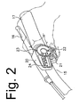
- shift controller 20 comprises two operating buttons 21 and 22 in the form of triangular pushbuttons disposed next to each other, an operating dial 23 disposed above operating buttons 21 and 22, and a liquid crystal display device 24 disposed to the left of operating dial 23 for displaying information such as current gear and speed.
- the operating button 21 on the left side may be used for manually shifting progressively from a lower gear ratio to a higher gear ratio.
- the operating button 22 on the right side may be used for manually shifting progressively from a higher gear ratio to a lower gear ratio.
- the operating dial 23 is used for switching between two automatic shifting modes (A1 and A2) and a manual shifting mode (M) using three detent positions.
- the two automatic shifting modes (A1 and A2) are modes for automatically shifting internal shifting hub 10 according to a bicycle speed signal derived from alternating current generating dynamo 19.
- the two automatic shifting modes (A1 and A2) are designed to allow shift timing (i.e., the threshold speed values at which shifting will occur) to be automatically changed during upshifting (shifting from the lower gear ratio speed to the higher gear ratio) or downshifting (shifting from the higher gear ratio to the lower gear ratio) to accommodate rider preference and physical capability.
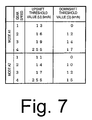
- Fig. 7 is a table illustrating a particular embodiment of upshift and downshift threshold values that may be used to control automatic shifting depending on bicycle speed in the two automatic shifting modes (A1) and (A2).
- Fig. 6 is a block diagram illustrating the structure of the overall bicycle control system. Heavy lines in Fig. 6 indicate lines carrying about 1 A of current at approximately 6 V, solid lines indicate lines carrying about 5 mA of current at approximately 3.5 V, and dotted lines indicate signal lines.
- Control unit 25 is operatively coupled to control switches 26 (which schematically represents the operating dial 23 and operating buttons 21 and 22 in the shift controller 20); to the liquid crystal display device 24; to a dynamo waveform shaping circuit 34 that generates a speed signal derived from the output of alternating current generating dynamo 19; to a rectifier circuit 33; to a power supply in the form of a power storage element 32 (e.g., a capacitor); to a power supply sensor in the form of a voltage sensor 27 for sensing a power characteristic such as the voltage of battery unit 32; to a light sensor 36; to an auto light circuit 35 for controlling the lamp 18; to a motor driver 28; to the operating position sensor 47 of motor unit 29, and to a transformer circuit 31.
- control switches 26 which schematically represents the operating dial 23 and operating buttons 21 and 22 in the shift controller 20
- a dynamo waveform shaping circuit 34 that generates a speed signal derived from the output of alternating current generating dynamo 19
- a rectifier circuit 33 to
- Transformer circuit 31 transforms the 6 V power stored in power storage element 32 into a control power supply of approximately 3.5 V. As shown in Fig. 6, transformer circuit 31 supplies this voltage to control unit 25, to motor driver 28, to rectifier circuit 33, and to auto-light circuit 35.
- Motor driver 28 operates on the 5 mA current supplied by power storage element 32, and it controls a 1A current supplied by power storage element 32 to operate shifting motor 45.
- Control unit 25 is a programmed unit that automatically controls shifting of internal shifting hub 10 via motor driver 28 according to travel speed. Control unit 25 also manually controls shifting of internal shifting hub 10 in response to signals from operating buttons 21 and 22. Control unit 25 also controls the operation of liquid crystal display device 24 disposed in shift controller 20. Control unit 25 controls lamp 18 by turning it on when surrounding light conditions fall below a certain prescribed brightness, and by turning it off when surrounding light conditions are above the prescribed brightness.
- Rectifier circuit 33 comprises, for example, a half-wave rectifier circuit that rectifies an alternating current output from alternating current generating dynamo 19 to a current of 1A (for example) and supplies this current to power storage element 32.
- Power storage element 32 may comprise, for example, a high-capacity capacitor that stores the direct current power that is output from the charging rectifier circuit 33.
- Power storage element 32 also may comprise a secondary cell such as a nickel cadmium battery, a lithium ion battery, a nickel-metal hydride battery, etc., in lieu of a capacitor.
- Battery replacement and recharging are unnecessary because power storage element 32 stores electrical power from alternating current generating dynamo 19, and components such as control unit 25 are operated using this electrical power. Monitoring remaining battery power and carrying along spare batteries also become unnecessary, and shifting can be done automatically without performing the cumbersome procedures required by conventional power sources.
- Voltage sensor 27 is disposed between power storage element 32 and motor driver 28. Voltage sensor 27 senses the voltage of power storage element 32 and provides this information to control unit 25. If the voltage goes below a predetermined voltage Vs, control unit 25 commands motor driver 28 to operate motor unit 29 to shift internal shifting hub in a desired or predetermined manner.
- the predetermined voltage Vs is established with reference to a minimum operating voltage Vi below which motor 45 typically becomes inoperable. For example, when the minimum operating voltage Vi for motor 45 is approximately 4 V, then Vs is set to approximately 4.5 V to provide a margin of safety. In a preferred embodiment, the predetermined voltage Vs will be in a range of from approximately 2% to approximately 20% higher than the minimum operating voltage Vi.
- Auto light circuit 35 supplies or interrupts the 1A current output from alternating current generating dynamo 19 to lamp 18 in response to on/off signal output from control unit 25.
- Control unit 25 generates these signal based on signals from light sensor 36 in such a manner that lamp 18 is switched on automatically when light levels fall below a prescribed limit, and it is switched off when light levels exceed the prescribed limit.
- Dynamo waveform shaping circuit 34 forms a speed signal from the alternating current output from alternating current generating dynamo 19. More specifically, a half-cycle is extracted from a sine wave alternating current signal, passed through a Schmitt circuit or some other appropriate waveform shaping circuit, and formed into a pulse signal corresponding to speed. Control unit 25 uses this signal to control the automatic shifting of the internal shifting hub 10 without requiring a separate speed sensor. Control unit 25 also uses this signal to calculate speed and distance and to determine whether the bicycle is in a stopped condition for a predetermined time interval (e.g., 10 minutes).
- a predetermined time interval e.g. 10 minutes
- alternating current generating dynamos generally have a plurality of circumferentially disposed magnetic poles
- alternating current generating dynamo 19 outputs an alternating current signal with a frequency related to the bicycle speed and the number of magnetic poles. Consequently, it is possible to obtain a larger number of signal pulses from the alternating current signal during each wheel rotation in comparison with a speed signal obtainable, for example, from a conventional speed sensor that detects a magnet mounted to the bicycle wheel. Therefore, the bicycle speed can be accurately detected within the space of one wheel rotation, and shifting can be controlled in real time with high precision. Furthermore, since shifting is controlled based on the alternating current signal from alternating current generating dynamo 19, it is no longer necessary to dispose shift control unit 12 in the vicinity of the bicycle wheel. No limitation is placed on the mounting position of shift control unit 12.
- control is performed by means of upshift threshold values and downshift threshold values as shown in Fig. 7.
- automatic shift mode (A1) when bicycle velocity reaches 13 km/h, the system upshifts from first gear to second gear. When bicycle velocity reaches 16 km/h, the system upshifts to third gear, and when bicycle velocity reaches 19 km/h, the system upshifts to fourth gear. When bicycle velocity subsequently slows to 17 km/h, the system downshifts from fourth gear to third gear. When bicycle velocity slows to 14 km/h, the system downshifts to second gear, and when bicycle velocity falls to 12 km/h the system downshifts to first gear.
- the shift timing for upshifting and the shift timing for downshifting are lowered toward the downshift end.
- control unit 25 may be understood from the flowcharts shown in Figs. 8-10.
- power storage element 32 is charged from the signals received from alternating current generating dynamo 19 through rectifier circuit 33.
- control unit 25 begins operation and performs an initialization operation in a Step S1 as shown in Fig. 8.
- Step S4 it is then determined in Step S4 whether or not control dial 23 is set to automatic shifting mode (A1). If so, then an automatic shifting (A1) process described below is performed in a Step S 11. In any event, it is then determined in a Step S5 whether or not control dial 23 is set to automatic shifting mode (A2). If so, then an automatic shifting (A2) process similar to automatic shifting (A1) process is performed in a Step S12. In any event, it is then determined in a Step S6 whether or not control dial 23 is set to manual shifting mode (M). If so, then a manual shifting (M) process described below is performed in a Step S 13. In any event, it is then determined in a Step S7 whether or not another process has been selected. If so, then the other process is performed in a Step S 14. Processing then returns to Step S2.
- the operating position VP of internal shifting hub 10 is set to a proper gear ratio depending on the bicycle speed S and the upshift and downshift threshold values indicated in Fig. 7. If the bicycle speed S passes the upshift or downshift threshold value for the current gear, then shifting is performed in one speed increments to set internal shifting hub 10 in the proper gear ratio.
- Fig. 9 is a flow chart of a particular embodiment of automatic shifting (A1) process of Step S11.
- the automatic shifting (A2) process of Step S12 differs from the automatic shifting (A1) process only by shift threshold values, so a separate description of automatic shifting (A2) process will not be provided.
- the operating position VP of operating position sensor 47 is acquired in a Step S21, and then current speed S of the bicycle is acquired in a Step S22 by means of the speed signal derived from alternating current generating dynamo 19. It is then determined in a Step S23 whether or not the acquired current bicycle speed S exceeds the upshift threshold value U(VP) shown in Fig. 7 corresponding to the operating position VP of operating position sensor 47.
- Step S25 If it is determined in Step S25 that internal shifting hub 10 currently is in fourth gear, then no further upshifting is possible. Of course, since the upshift threshold value for fourth gear is 255, which would be inconceivable with normal shifting, it is not normal to pass through this step. In any event, no further action is taken to upshift internal shifting hub 10 in either case, and processing moves to Step S24.
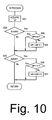
- Fig. 10 is a flow chart illustrating a particular embodiment of the manual shifting (M) process of Step S6 in Fig. 8.
- the operating position VP of operating position sensor 47 is acquired in a Step S31. It is then determined in a Step S32 whether or not operating button 21 is being pressed. If so, it is then determined in a Step S34 whether or not internal shifting hub 10 currently is in fourth gear. If not, then the operating position VP is incremented by one in a Step S35, and control unit 25 outputs a signal for upshifting internal shifting hub 10 accordingly.
- Step S34 it is determined in Step S34 that internal shifting hub 10 currently is in fourth gear, then no further upshifting is possible. Accordingly, no further action is taken to upshift internal shifting hub 10 at this time, and processing moves to Step S33.
- Step S33 it is then determined in a Step S33 whether or not operating button 22 is being pressed. If so, it is then determined in a Step S36 whether or not internal shifting hub 10 currently is in first gear. If not, then the operating position VP is decremented by one in a Step S37, and control unit 25 outputs a signal to downshift internal shifting hub 10 accordingly. On the other hand, if it is determined in Step S36 that internal shifting hub 10 currently is in first gear, then no further downshifting is possible. Accordingly, no further action is taken to downshift internal shifting hub 10 at this time, and processing returns to the main routine.
- While a shift motor was used in the described embodiment to operate the bicycle transmission, the transmission also could be operated by some other mechanism, such as a solenoid. Placement of the motor unit 29 (including the shift motor) and the control unit 25 is not restricted, and these components could be placed in many locations. For example, motor unit 29 could be disposed at internal shifting hub 10 or other transmission to drive the transmission directly. If desired, control unit 25 could be disposed with shift controller 20.
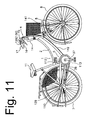
- Fig. 11 is a side view of a bicycle that is equipped for that purpose.
- a signal provider 113 such as a magnet may be installed on gear crank 37
- a rotation sensor 112 such as a reed switch may be installed on frame body 2 to sense crank rotation speed.
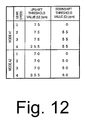
- an upper limit and a lower limit for crank rotation speed for each gear position could be set as shift threshold values as shown in Fig. 12.
- the same values are set for each gear position, but different shift threshold values could be provided instead.
- upshifting is performed when the current crank rotation speed S exceeds the upshift threshold value
- downshifting is performed when the current crank rotation speed S falls below the downshift threshold value.
- motor unit 29 and circuit unit 30 are not arranged in lamp case 13. Instead, a motor unit 129 is disposed at an internal shifting hub 110, with internal shifting hub 110 being actuated directly.
- a circuit unit 130 like that shown in Fig. 5 including a control unit 25 is disposed inside a shift controller 120. Power from an alternating current generating dynamo 19 inside dynamo hub 8 is supplied to circuit unit 130 via electrical wiring 141, and the power from alternating current generating dynamo 19 charges power storage element 32.
- Shift controller 120 and internal shifting hub 110 are connected by electrical wiring 142 instead of by a shift cable, a shift signal is output by control unit 25 to motor unit 129, and an operating position signal is output by an operating position sensor to control unit 25 inside shift controller 120 by means of electrical wiring 142.
- control unit 25 could be disposed inside internal shifting hub 110, and control unit 25 and shift controller 120 could be connected by electrical wiring.
- the predetermined gear ratio could be any intermediate gear ratio, preferably but not necessarily excepting the highest gear and the lowest gear. In any event, it is particularly advantageous for the chosen predetermined gear ratio to be close to the ratio of crank rotation speed to rear wheel rotation speed in an ordinary bicycle, such as a ratio in the range of from approximately 1.2 to approximately 1.5.
- Fig. 13 is a flow chart illustrating processing for an embodiment that includes such a running condition time sensor such as a stop time sensor. After initialization in a step S41, current velocity S is acquired in a Step S42. It is then determined in a Step S43 whether or not current velocity S equals 0 (i.e., the bicycle is stopped).
- Step S44 processing moves to Step S44, and a stop time sensor such as a timer T for measuring stop time is turned off. This ensures that timer T will be turned off during a brief stop.
- Step S45 through Step S48 and Step S55 through Step S58 in Fig. 13 are the same as Step S4 through Step S7 and Step S11 through Step S 14 in Fig. 8, respectively, and need not be described.
- Step S43 If it is determined in Step S43 that the bicycle is stopped, then it is determined in a Step S49 whether or not timer T already has been turned on (started). If not, then timer T is turned on in a Step S50, and processing moves to Step S45. However, if timer T already has been turned on, it is then determined in a Step S51 whether or not 10 or more minutes have elapsed since timer T was turned on (i.e. whether the bicycle has been stopped for 10 or more minutes). If the bicycle has not been stopped for 10 or more minutes, then processing moves to Step S45.
- stop time is not limited to that described here, nor is stop time limited to 10 minutes. Any measuring device may be used, and any time interval that allows a distinction to be made from a temporary stop during riding, such as waiting for a stoplight, would be acceptable.
- the stop interval is preferably but not necessarily at least five minutes.
- the bicycle is shifted to a desired or predetermined gear whenever there is a risk that voltage will drop to an undesirable level based on time (due to parking for an extended period, for example) a subsequent drop in voltage to the point that the bicycle transmission can no longer operate will not create discomfort for the rider.
- the predetermined time interval can be determined using a timer function provided by the microcomputer in control unit 25, the design of the control device can be simplified.
Landscapes
- Engineering & Computer Science (AREA)
- Chemical & Material Sciences (AREA)
- Combustion & Propulsion (AREA)
- Transportation (AREA)
- Mechanical Engineering (AREA)
- Control Of Transmission Device (AREA)
- Gear-Shifting Mechanisms (AREA)
Applications Claiming Priority (2)
| Application Number | Priority Date | Filing Date | Title |
|---|---|---|---|
| JP2003366921A JP3994081B2 (ja) | 2003-10-28 | 2003-10-28 | 自転車用変速制御装置 |
| JP2003366921 | 2003-10-28 |
Publications (3)
| Publication Number | Publication Date |
|---|---|
| EP1527990A2 true EP1527990A2 (fr) | 2005-05-04 |
| EP1527990A3 EP1527990A3 (fr) | 2008-09-24 |
| EP1527990B1 EP1527990B1 (fr) | 2013-01-09 |
Family
ID=34420110
Family Applications (1)
| Application Number | Title | Priority Date | Filing Date |
|---|---|---|---|
| EP04025458A Expired - Lifetime EP1527990B1 (fr) | 2003-10-28 | 2004-10-26 | Dispositif de commande pour transmission de bicyclette |
Country Status (5)
| Country | Link |
|---|---|
| US (2) | US7144027B2 (fr) |
| EP (1) | EP1527990B1 (fr) |
| JP (1) | JP3994081B2 (fr) |
| CN (1) | CN100415594C (fr) |
| TW (1) | TWI239930B (fr) |
Cited By (1)
| Publication number | Priority date | Publication date | Assignee | Title |
|---|---|---|---|---|
| WO2016155714A1 (fr) * | 2015-04-02 | 2016-10-06 | Schaeffler Technologies AG & Co. KG | Dispositif et procédé permettant un changement de vitesse automatique d'un mécanisme de changement de vitesse d'un vélo |
Families Citing this family (26)
| Publication number | Priority date | Publication date | Assignee | Title |
|---|---|---|---|---|
| US7503420B2 (en) * | 2006-02-01 | 2009-03-17 | Shimano Inc. | Bicycle control device |
| US7874567B2 (en) | 2009-03-02 | 2011-01-25 | Shimano Inc. | Bicycle shifting control apparatus |
| US7900946B2 (en) | 2009-03-31 | 2011-03-08 | Shimano Inc. | Bicycle shifting control apparatus |
| WO2010135472A2 (fr) * | 2009-05-19 | 2010-11-25 | Ev-Ip, Llc | Procédés et dispositif pour utiliser des véhicules électriques |
| US20110080071A1 (en) * | 2009-10-06 | 2011-04-07 | Tzu-Wei Liu | Bicycle power supply module for supplying power to electrical devices on a bicycle and related bicycle |
| KR100966120B1 (ko) * | 2009-12-28 | 2010-06-25 | 이창용 | 자전거의 자동 변속 장치 |
| US10604203B2 (en) * | 2010-10-12 | 2020-03-31 | Weng-Dah Ken | Green bike |
| EP2640629A1 (fr) * | 2010-11-18 | 2013-09-25 | Sean Michael Simpson | Système et procédé permettant de contrôler la transmission d'un véhicule à propulsion humaine |
| TW201249706A (en) * | 2011-06-14 | 2012-12-16 | J D Components Co Ltd | Automatic speed change system of bicycle having training mode |
| US8886417B2 (en) * | 2011-09-09 | 2014-11-11 | Sram, Llc | Bicycles with electronic shifting systems and methods |
| US9394026B2 (en) * | 2013-07-01 | 2016-07-19 | 3G Bikes, Llc | Step-through bicycle frame |
| JP2015027861A (ja) * | 2013-07-05 | 2015-02-12 | 株式会社シマノ | 自転車制御システム |
| US9676444B2 (en) * | 2013-10-23 | 2017-06-13 | Sram, Llc | Electromechanical rear derailleur |
| JP5778830B1 (ja) | 2014-05-29 | 2015-09-16 | 株式会社シマノ | 自転車用の変速制御装置、電動アシストシステム、および、自転車用の変速制御方法 |
| US10556639B2 (en) * | 2016-09-13 | 2020-02-11 | Brandon Rodgers | Wireless sprocket shifting control system |
| JP6688726B2 (ja) * | 2016-12-26 | 2020-04-28 | 株式会社シマノ | 自転車用制御装置および自転車用制御システム |
| US11110993B2 (en) * | 2017-09-13 | 2021-09-07 | Brandon Rodgers | Damping device adapted for integration within a gearshifting system |
| TWI644832B (zh) * | 2017-11-17 | 2018-12-21 | 彥豪金屬工業股份有限公司 | 電子變速器之電源控制裝置及電源控制方法 |
| US10322770B1 (en) * | 2017-11-27 | 2019-06-18 | Metal Industries Research & Development Centre | Electricity aided bicycle and auxiliary power controlling method thereof |
| JP7120871B2 (ja) * | 2018-10-02 | 2022-08-17 | 株式会社シマノ | 制御装置および変速システム |
| US11459061B2 (en) | 2019-01-12 | 2022-10-04 | Sram, Llc | Bicycle component motion control |
| CN111532361A (zh) * | 2019-02-03 | 2020-08-14 | 单车喜客自行车人文精品店有限公司 | 自行车骑乘信息的推播中继装置及其推播方法 |
| US10640171B2 (en) * | 2019-03-25 | 2020-05-05 | Hazem Nihad Hamed | Automatic bicycle shifter and user interface |
| JP7490593B2 (ja) * | 2021-02-15 | 2024-05-27 | 株式会社シマノ | 人力駆動車用の制御装置 |
| US11724775B1 (en) * | 2022-04-04 | 2023-08-15 | Shimano Inc. | Control device and derailleur for human-powered vehicle |
| JP7737342B2 (ja) * | 2022-04-12 | 2025-09-10 | 株式会社シマノ | 人力駆動車用の制御システム |
Citations (1)
| Publication number | Priority date | Publication date | Assignee | Title |
|---|---|---|---|---|
| JP2003011879A (ja) | 2001-06-29 | 2003-01-15 | Shimano Inc | 自転車用変速制御装置 |
Family Cites Families (17)
| Publication number | Priority date | Publication date | Assignee | Title |
|---|---|---|---|---|
| US5059158A (en) * | 1990-05-08 | 1991-10-22 | E.B.T., Inc. | Electronic transmission control system for a bicycle |
| US5213548A (en) * | 1992-03-02 | 1993-05-25 | Colbert Ralph G | Gear shifting system for derailleur equipped bicycle |
| US5261858A (en) * | 1992-06-19 | 1993-11-16 | Browning Automatic Transmission | Method and system for computer-controlled bicycle gear shifting |
| US5551315A (en) * | 1994-02-03 | 1996-09-03 | Pikoulas; George W. | Automatic gear changing system |
| CN1050812C (zh) * | 1995-03-28 | 2000-03-29 | 王维德 | 以电脑控制自行车自动变速的方法与装置 |
| JP2988659B2 (ja) * | 1996-09-04 | 1999-12-13 | 株式会社シマノ | 自転車の擬似クランク回転数演算装置 |
| JPH10181671A (ja) | 1996-12-25 | 1998-07-07 | Jeco Co Ltd | 自動変速装置 |
| US6047230A (en) * | 1997-02-27 | 2000-04-04 | Spencer; Marc D. | Automatic bicycle transmission |
| JPH11291971A (ja) | 1998-04-08 | 1999-10-26 | Bridgestone Cycle Co | 自動変速装置 |
| JP2000038187A (ja) | 1998-07-23 | 2000-02-08 | Bridgestone Cycle Co | 補助動力付自転車用自動変速装置 |
| JP2000266177A (ja) | 1999-03-16 | 2000-09-26 | Bridgestone Cycle Co | 自動変速装置における低電圧検出装置 |
| JP2000283283A (ja) | 1999-04-01 | 2000-10-13 | Bridgestone Cycle Co | 自動変速制御装置 |
| US6367833B1 (en) * | 2000-09-13 | 2002-04-09 | Shimano, Inc. | Automatic shifting control device for a bicycle |
| JP2002187584A (ja) * | 2000-12-22 | 2002-07-02 | Shimano Inc | 自転車用電動ユニットの駆動制御回路 |
| JP2003120799A (ja) * | 2001-10-15 | 2003-04-23 | Shimano Inc | 自転車用変速制御装置 |
| JP3770390B2 (ja) * | 2002-09-19 | 2006-04-26 | 株式会社シマノ | 自転車用変速制御装置 |
| JP2005313748A (ja) * | 2004-04-28 | 2005-11-10 | Shimano Inc | 自転車用変速制御装置 |
-
2003
- 2003-10-28 JP JP2003366921A patent/JP3994081B2/ja not_active Expired - Fee Related
-
2004
- 2004-06-29 TW TW093119177A patent/TWI239930B/zh not_active IP Right Cessation
- 2004-10-22 US US10/904,092 patent/US7144027B2/en not_active Expired - Fee Related
- 2004-10-26 EP EP04025458A patent/EP1527990B1/fr not_active Expired - Lifetime
- 2004-10-28 CN CNB2004100877804A patent/CN100415594C/zh not_active Expired - Fee Related
-
2006
- 2006-10-31 US US11/554,863 patent/US7311322B2/en not_active Expired - Lifetime
Patent Citations (1)
| Publication number | Priority date | Publication date | Assignee | Title |
|---|---|---|---|---|
| JP2003011879A (ja) | 2001-06-29 | 2003-01-15 | Shimano Inc | 自転車用変速制御装置 |
Cited By (2)
| Publication number | Priority date | Publication date | Assignee | Title |
|---|---|---|---|---|
| WO2016155714A1 (fr) * | 2015-04-02 | 2016-10-06 | Schaeffler Technologies AG & Co. KG | Dispositif et procédé permettant un changement de vitesse automatique d'un mécanisme de changement de vitesse d'un vélo |
| US10239582B2 (en) | 2015-04-02 | 2019-03-26 | Schaeffler Technologies AG & Co. KG | Device and method for automatically shifting a gearshift mechanism of a bicycle |
Also Published As
| Publication number | Publication date |
|---|---|
| TWI239930B (en) | 2005-09-21 |
| JP3994081B2 (ja) | 2007-10-17 |
| JP2005132122A (ja) | 2005-05-26 |
| US7144027B2 (en) | 2006-12-05 |
| TW200514727A (en) | 2005-05-01 |
| CN100415594C (zh) | 2008-09-03 |
| CN1611415A (zh) | 2005-05-04 |
| US7311322B2 (en) | 2007-12-25 |
| US20070068319A1 (en) | 2007-03-29 |
| EP1527990B1 (fr) | 2013-01-09 |
| EP1527990A3 (fr) | 2008-09-24 |
| US20050098978A1 (en) | 2005-05-12 |
Similar Documents
| Publication | Publication Date | Title |
|---|---|---|
| EP1527990B1 (fr) | Dispositif de commande pour transmission de bicyclette | |
| US6959939B2 (en) | Electronic bicycle shift control device | |
| EP1381021B1 (fr) | Accessoire de bicyclette controllé par mesure de luminosité | |
| US7165641B2 (en) | Bicycle power supply with discharge function | |
| USRE43562E1 (en) | Bicycle shift control apparatus that prevents undesirable chain angles | |
| US7288038B2 (en) | Bicycle shift control apparatus with preferential shifting | |
| US6959941B2 (en) | Bicycle shift control apparatus that selectively restricts speed stages | |
| EP1465317B1 (fr) | Alimentation de puissance pour bicyclette avec courant de fuite de batterie reduite | |
| EP1383223B1 (fr) | Circuit pour fournir le courant électrique à un accessoire de bicyclette | |
| US20070296176A1 (en) | Bicycle shift control device that responds to a manually operated switch | |
| EP1424276B1 (fr) | Unité de commande électronique pour bicyclette |
Legal Events
| Date | Code | Title | Description |
|---|---|---|---|
| PUAI | Public reference made under article 153(3) epc to a published international application that has entered the european phase |
Free format text: ORIGINAL CODE: 0009012 |
|
| AK | Designated contracting states |
Kind code of ref document: A2 Designated state(s): AT BE BG CH CY CZ DE DK EE ES FI FR GB GR HU IE IT LI LU MC NL PL PT RO SE SI SK TR |
|
| AX | Request for extension of the european patent |
Extension state: AL HR LT LV MK |
|
| RAP1 | Party data changed (applicant data changed or rights of an application transferred) |
Owner name: SHIMANO INC. |
|
| PUAL | Search report despatched |
Free format text: ORIGINAL CODE: 0009013 |
|
| AK | Designated contracting states |
Kind code of ref document: A3 Designated state(s): AT BE BG CH CY CZ DE DK EE ES FI FR GB GR HU IE IT LI LU MC NL PL PT RO SE SI SK TR |
|
| AX | Request for extension of the european patent |
Extension state: AL HR LT LV MK |
|
| 17P | Request for examination filed |
Effective date: 20090129 |
|
| AKX | Designation fees paid |
Designated state(s): DE IT NL |
|
| 17Q | First examination report despatched |
Effective date: 20110614 |
|
| GRAP | Despatch of communication of intention to grant a patent |
Free format text: ORIGINAL CODE: EPIDOSNIGR1 |
|
| GRAS | Grant fee paid |
Free format text: ORIGINAL CODE: EPIDOSNIGR3 |
|
| GRAA | (expected) grant |
Free format text: ORIGINAL CODE: 0009210 |
|
| AK | Designated contracting states |
Kind code of ref document: B1 Designated state(s): DE IT NL |
|
| REG | Reference to a national code |
Ref country code: DE Ref legal event code: R096 Ref document number: 602004040695 Country of ref document: DE Effective date: 20130314 |
|
| REG | Reference to a national code |
Ref country code: NL Ref legal event code: VDEP Effective date: 20130109 |
|
| PG25 | Lapsed in a contracting state [announced via postgrant information from national office to epo] |
Ref country code: NL Free format text: LAPSE BECAUSE OF FAILURE TO SUBMIT A TRANSLATION OF THE DESCRIPTION OR TO PAY THE FEE WITHIN THE PRESCRIBED TIME-LIMIT Effective date: 20130109 |
|
| PLBE | No opposition filed within time limit |
Free format text: ORIGINAL CODE: 0009261 |
|
| STAA | Information on the status of an ep patent application or granted ep patent |
Free format text: STATUS: NO OPPOSITION FILED WITHIN TIME LIMIT |
|
| 26N | No opposition filed |
Effective date: 20131010 |
|
| REG | Reference to a national code |
Ref country code: DE Ref legal event code: R097 Ref document number: 602004040695 Country of ref document: DE Effective date: 20131010 |
|
| PGFP | Annual fee paid to national office [announced via postgrant information from national office to epo] |
Ref country code: IT Payment date: 20161024 Year of fee payment: 13 |
|
| PG25 | Lapsed in a contracting state [announced via postgrant information from national office to epo] |
Ref country code: IT Free format text: LAPSE BECAUSE OF NON-PAYMENT OF DUE FEES Effective date: 20171026 |
|
| PGFP | Annual fee paid to national office [announced via postgrant information from national office to epo] |
Ref country code: DE Payment date: 20220621 Year of fee payment: 19 |
|
| P01 | Opt-out of the competence of the unified patent court (upc) registered |
Effective date: 20230428 |
|
| REG | Reference to a national code |
Ref country code: DE Ref legal event code: R119 Ref document number: 602004040695 Country of ref document: DE |
|
| PG25 | Lapsed in a contracting state [announced via postgrant information from national office to epo] |
Ref country code: DE Free format text: LAPSE BECAUSE OF NON-PAYMENT OF DUE FEES Effective date: 20240501 |