EP1528190A1 - Tür mit verriegelbarem an dieser Tür angepastem Handgriff - Google Patents
Tür mit verriegelbarem an dieser Tür angepastem Handgriff Download PDFInfo
- Publication number
- EP1528190A1 EP1528190A1 EP04292560A EP04292560A EP1528190A1 EP 1528190 A1 EP1528190 A1 EP 1528190A1 EP 04292560 A EP04292560 A EP 04292560A EP 04292560 A EP04292560 A EP 04292560A EP 1528190 A1 EP1528190 A1 EP 1528190A1
- Authority
- EP
- European Patent Office
- Prior art keywords
- handle
- door
- face
- support
- flap
- Prior art date
- Legal status (The legal status is an assumption and is not a legal conclusion. Google has not performed a legal analysis and makes no representation as to the accuracy of the status listed.)
- Withdrawn
Links
- 239000002184 metal Substances 0.000 description 2
- 230000001680 brushing effect Effects 0.000 description 1
- 238000010586 diagram Methods 0.000 description 1
- 230000000284 resting effect Effects 0.000 description 1
Images

Classifications
-
- E—FIXED CONSTRUCTIONS
- E05—LOCKS; KEYS; WINDOW OR DOOR FITTINGS; SAFES
- E05B—LOCKS; ACCESSORIES THEREFOR; HANDCUFFS
- E05B9/00—Lock casings or latch-mechanism casings ; Fastening locks or fasteners or parts thereof to the wing
- E05B9/08—Fastening locks or fasteners or parts thereof, e.g. the casings of latch-bolt locks or cylinder locks to the wing
-
- E—FIXED CONSTRUCTIONS
- E05—LOCKS; KEYS; WINDOW OR DOOR FITTINGS; SAFES
- E05B—LOCKS; ACCESSORIES THEREFOR; HANDCUFFS
- E05B1/00—Knobs or handles for wings; Knobs, handles, or press buttons for locks or latches on wings
- E05B1/0015—Knobs or handles which do not operate the bolt or lock, e.g. non-movable; Mounting thereof
-
- E—FIXED CONSTRUCTIONS
- E05—LOCKS; KEYS; WINDOW OR DOOR FITTINGS; SAFES
- E05B—LOCKS; ACCESSORIES THEREFOR; HANDCUFFS
- E05B65/00—Locks or fastenings for special use
- E05B65/02—Locks or fastenings for special use for thin, hollow, or thin-metal wings
Definitions
- Metal furniture such as cloakroom cupboards or Lockable lockers, usually have a door with a lock key or a padlock and a handle, usually made of plastic, intended in particular to identify, by number or name, the compartment closed by the door and of course, to grab the door for rotate it.
- At least one hole is drilled in the door to introduce a barrel, which barrel has an external threaded portion extended by a shoulder. So, the barrel is mounted across the door in the bore, the shoulder resting in the perimeter of the bore on a front face of the door and it is secured by at least one screw ring which bears against the door around said piercing on a rear face opposite to the front face.
- a handle it is necessary to mount a handle.
- This mode of implementation is incompatible with a production in series of doors equipped with key locks of the aforementioned type, taking into productivity requirements.
- the present invention aims to provide a handle incorporating a lock and a capability of an identification marking, which can be mounted from fixed and secure way, quickly and easily, on a door with snap holes provided for this purpose.
- the present invention relates to a set lockable door and handle adapted to said door, characterized in that that the handle is provided with a support journal of a barrel with a key bearing a locking member such as a threshing cam, said support being provided with a flange, the handle further comprising a pivoting flap provided with a boss and grooved studs, the door being equipped with a profiled hole to match the support section of the barrel and allow the handle to slide parallel to the door surface up to the edge of the edge of the profiled hole on the bottom of the flange, as well as passage holes of the grooved studs arranged for their edge to be housed in the grooves of the grooved studs after sliding of the handle, the door further comprising a hole snap-in profile of the shutter boss after sliding of the handle and pivoting of the flap.
- a feature of the invention lies in the implementation a single-block handle that has a marking area and that is adapted to be mounted easily by snapping on the door in which holes or holes were made beforehand.
- the handle according to the invention is likely to be installed simply from this face before and to be secured to the door by snapping, without can then withdraw it from this same face.
- said handle having a free face and a bearing face against said door, said flap is pivotally mounted through a light formed in said handle, said opening opening in said face free and in said support face. So, the light or opening, which is arranged, preferably in the center of the handle, allows to house the shutter which, once rotated, is totally retracted.
- said component has an anterior face and a posterior face, said boss projecting from said posterior face. In this way, when shutter is driven to its pivoting position, the boss comes through the same, snap into said profiled hole.
- said flap comprises locking lugs terminated by a hook, said projecting locking lugs of said rear face, and in said pivoting position of said flap the hooks are hooked into said bearing face of said handle or in the means provided for this purpose. So after the shutter has been driven into its pivoting position, it is imprisoned in the said light thanks to the hooks without being able to extract it from the free face of the handle. Only an action on the locking lugs from the support face of the handle, allows to release the shutter, which is impossible, door closed.
- said grooved studs have radial grooves defining an average plane substantially parallel to said bearing face, said radial grooves adjacent said support face.
- said flange is formed by a groove formed in said support, the edge of said profiled hole being adapted to come engage in said groove.
- said groove is provided on the same mean plane of said grooves radials.
- the handle is made of plastic, for example is molded from a single piece with said flap.
- Figures 1 and 2 show a handle 1 substantially circular, having a free face 20 and a bearing face 22.
- the handle 1 comprises a support 3 preinstalled, carrying a key cylinder 4, said barrel 4 being itself equipped with a locking member, in this example, a cam drummer 7.
- the handle 1 is adapted to be installed on a door P applied against a wall before the door P.
- the support 3 is provided at its base with a groove forming a collar 10 which comes opposite the support face 22.
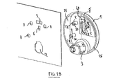
- the handle 1 is represented by three-quarter rear. It has a cup shape provided with a rim 24 substantially circular whose slice 26 defines a first middle plane and corresponds at the bearing surface 22.
- the handle 1 also bears grooved studs 2 parallel projections projecting from the same side as the support 3.
- Grooved studs 2 extend beyond said first average plane defined by the slice 26 and have at free end 28, radial grooves 30, grooves radial members 30 which extend along a section of said grooved studs 2, on a surface corresponding substantially to one-third of the section of in order not to excessively weaken these grooved studs 2.
- these radial grooves 30 are arranged substantially in one and the same second middle plane, in which also extends the groove forming flange 10, this second middle plane extending at a close distance of said bearing face 22 of the handle 1. Furthermore, these grooves 30 have a width corresponding substantially to the thickness of the front wall of the door P.
- a pivoting shutter 8 in look of a light or opening 8 '.
- the light 8 ' extends substantially radially from the center of the handle 1, and the shutter 8 is mounted articulated at the end of the light 8 'located near the center of the handle 1.
- Said shutter 8 of a size substantially identical to that of the 8 ', has an anterior face 32 and a posterior face 34, and it is provided with a projection boss 9 projecting from its posterior face 34.
- it is equipped with locking lugs 36 at the end of its posterior face 34 opposite its pivot axis, the pins of locking 36 being terminated by a hook 38 oriented in a opposite direction to brushing 9.
- FIG. 4 illustrates a partial view
- the door P is pierced by a hole 12 receiving the support 3 of the handle 1, sized to allow, after introduction of the support 3 orthogonally, a sliding of the handle 1 parallel to the door P until the edge of the hole 12 is in abutment in the bottom of the groove forming the collar 10.
- Door P also has holes 11 shown in FIG. 4, for the passage of the grooved studs 2 of the handle 1, the holes 11 having a diameter allowing the sliding of the handle 1 to the stop of grooves 30 grooved studs 2 on the edges of these holes 11.
- the radial grooves 30 of the stud grooved 2 and the flange groove 10 are all located opposite respectively of the edge of the hole in which the grooved studs 2 and the support 3, are engaged.
- the door P is furthermore provided with a profiled hole 6 illustrated in FIG. 4. allowing, after sliding of the handle 1 and pivoting of the flap 8, locking the handle 1 by snapping the boss 9 into the hole profile 6.
- the handle 1 is completely blocked by compared to the door P. Indeed, by pivoting the flap 8, the boss 9 penetrates the profiled hole 6, and at the end of the race the hooks 38 locking lugs 36 engage against the bar 40 of the handle 1 at the edge of the eccentric end of the light 8 ', as shown in Figure 3.
- the handle is integral in translation of the wall of the door P, thanks to the boss 9, whose dimensions are substantially equal to those of the profiled hole 6, but also, the shutter 8 is kept prisoner of the handle 1 inside the light 8 ', thanks at the hooks 38 of the locking lugs 36.
- the door P furthermore comprises a through hole 5 giving access to the opposite face of the door P so as to be able to release the locking lugs 38 of the support bar 40 of the handle 1 in discarding said hooks by means of a tool for example a screwdriver, but that, when the door is open.
- the handle 1 is made of plastic and is assembled to in advance to be delivered, ready to assemble, to the furniture manufacturer metal. Such an installed handle is shown in FIG. three-quarter view.
Landscapes
- Engineering & Computer Science (AREA)
- Mechanical Engineering (AREA)
- Securing Of Glass Panes Or The Like (AREA)
Applications Claiming Priority (2)
| Application Number | Priority Date | Filing Date | Title |
|---|---|---|---|
| FR0312726 | 2003-10-30 | ||
| FR0312726A FR2861782B1 (fr) | 2003-10-30 | 2003-10-30 | Ensemble de porte et de poignee verrouillable adaptee a ladite porte |
Publications (1)
| Publication Number | Publication Date |
|---|---|
| EP1528190A1 true EP1528190A1 (de) | 2005-05-04 |
Family
ID=34400886
Family Applications (1)
| Application Number | Title | Priority Date | Filing Date |
|---|---|---|---|
| EP04292560A Withdrawn EP1528190A1 (de) | 2003-10-30 | 2004-10-28 | Tür mit verriegelbarem an dieser Tür angepastem Handgriff |
Country Status (2)
| Country | Link |
|---|---|
| EP (1) | EP1528190A1 (de) |
| FR (1) | FR2861782B1 (de) |
Cited By (5)
| Publication number | Priority date | Publication date | Assignee | Title |
|---|---|---|---|---|
| EP2055867A1 (de) * | 2006-03-02 | 2009-05-06 | DIRAK Dieter Ramsauer Konstruktionselemente GmbH | Griff mit Verschlusseinsatz |
| FR2944825A1 (fr) * | 2009-04-27 | 2010-10-29 | Bezault Sas | Dispositif de fixation de ferrure notamment pour fenetres en aluminium ou matiere plastique, ferrure et vantail ou cadre dormant equipes. |
| EP2924203A1 (de) * | 2014-03-27 | 2015-09-30 | Abb Ag | Griff für eine Tür von einem Schaltschrank und Schaltschrank |
| WO2022238199A1 (en) * | 2021-05-10 | 2022-11-17 | Industrilås I Nässjö Aktiebolag | Fitting for an openable element |
| US20230313566A1 (en) * | 2022-03-30 | 2023-10-05 | Beijing Xiaomi Mobile Software Co., Ltd. | Door lock device and anti-theft door |
Citations (3)
| Publication number | Priority date | Publication date | Assignee | Title |
|---|---|---|---|---|
| US4850209A (en) * | 1986-04-28 | 1989-07-25 | The Eastern Company | Latch and lock housings, handles and mounting brackets |
| US5046340A (en) * | 1984-04-18 | 1991-09-10 | The Eastern Company | Latch and lock assemblies with spring-biased pivot bolts |
| FR2816654A1 (fr) * | 2000-11-10 | 2002-05-17 | Ronis Sa | Porte coulissante a serrure |
-
2003
- 2003-10-30 FR FR0312726A patent/FR2861782B1/fr not_active Expired - Fee Related
-
2004
- 2004-10-28 EP EP04292560A patent/EP1528190A1/de not_active Withdrawn
Patent Citations (3)
| Publication number | Priority date | Publication date | Assignee | Title |
|---|---|---|---|---|
| US5046340A (en) * | 1984-04-18 | 1991-09-10 | The Eastern Company | Latch and lock assemblies with spring-biased pivot bolts |
| US4850209A (en) * | 1986-04-28 | 1989-07-25 | The Eastern Company | Latch and lock housings, handles and mounting brackets |
| FR2816654A1 (fr) * | 2000-11-10 | 2002-05-17 | Ronis Sa | Porte coulissante a serrure |
Cited By (8)
| Publication number | Priority date | Publication date | Assignee | Title |
|---|---|---|---|---|
| EP2055867A1 (de) * | 2006-03-02 | 2009-05-06 | DIRAK Dieter Ramsauer Konstruktionselemente GmbH | Griff mit Verschlusseinsatz |
| FR2944825A1 (fr) * | 2009-04-27 | 2010-10-29 | Bezault Sas | Dispositif de fixation de ferrure notamment pour fenetres en aluminium ou matiere plastique, ferrure et vantail ou cadre dormant equipes. |
| EP2924203A1 (de) * | 2014-03-27 | 2015-09-30 | Abb Ag | Griff für eine Tür von einem Schaltschrank und Schaltschrank |
| WO2022238199A1 (en) * | 2021-05-10 | 2022-11-17 | Industrilås I Nässjö Aktiebolag | Fitting for an openable element |
| CN117396658A (zh) * | 2021-05-10 | 2024-01-12 | 奈舍工业有限公司 | 用于可打开元件的配件 |
| US12385300B2 (en) | 2021-05-10 | 2025-08-12 | Industrilas I Nassjo Aktiebolag | Fitting for an openable element |
| US20230313566A1 (en) * | 2022-03-30 | 2023-10-05 | Beijing Xiaomi Mobile Software Co., Ltd. | Door lock device and anti-theft door |
| US12559982B2 (en) * | 2022-03-30 | 2026-02-24 | Beijing Xiaomi Mobile Software Co., Ltd. | Door lock device and anti-theft door |
Also Published As
| Publication number | Publication date |
|---|---|
| FR2861782A1 (fr) | 2005-05-06 |
| FR2861782B1 (fr) | 2006-01-13 |
Similar Documents
| Publication | Publication Date | Title |
|---|---|---|
| FR2761127A1 (fr) | Article a fixer en aveugle et vehicule le comportant | |
| FR2754846A1 (fr) | Poignee a profil bas | |
| EP3203000B1 (de) | Schloss eines öffnungsflügels mit einem elastisch einklinkbaren sockel | |
| EP1722453B1 (de) | Einbaudose | |
| EP1528190A1 (de) | Tür mit verriegelbarem an dieser Tür angepastem Handgriff | |
| FR2927677A3 (fr) | Module d'assemblage verrouille | |
| EP3771800A1 (de) | System, das ein aufrollrohr eines rollladens und einen sperrriegel umfasst, und rollladenanlage, die ein solches system umfasst | |
| FR2761720A1 (fr) | Ferrure de verrouillage pour ouvrant coulissant | |
| FR2583837A1 (fr) | Douille d'espacement pour la fixation d'une ferrure sur un profil creux comportant une partie avancante | |
| EP2960406B1 (de) | Vorrichtung zum öffnen und schliessen eines artikels, insbesondere eines lederwaren-artikels, und artikel, der eine solche vorrichtung umfasst | |
| EP1808560B1 (de) | Verschlussvorrichtung für einen Kasten | |
| FR2734305A1 (fr) | Gond composite | |
| WO2019171264A1 (fr) | Dispositif d'obturation d'une ouverture dans la paroi d'un batiment | |
| EP1792033B1 (de) | Strassenmöbelanordnung | |
| CA2764119C (fr) | Ventouse electromagnetique comportant une source lumineuse | |
| EP0923176B1 (de) | Greifhalter für Einbaudose und entsprechende Einbaudose | |
| FR2700356A1 (fr) | Dispositif de fixation du corps d'une serrure dans un ajour d'une tôle. | |
| FR2897908A1 (fr) | Agencement de fixation | |
| EP2586938B1 (de) | Verriegelungsvorrichtung für ein Öffnungselement | |
| FR2911358A3 (fr) | Dispositif de serrure et cle pour boitiers electriques ou electroniques. | |
| FR2988759A1 (fr) | Ferrure en applique avec embout de dilatation d'un canon de montage | |
| FR2887310A1 (fr) | Dispositif de fixation d'un objet tel qu'une plaque a un support adjacent | |
| EP4534781A1 (de) | Verriegelungsbeschlag-steuervorrichtung für tür- oder fensterrahmen | |
| EP2186978A1 (de) | Griffbefestigung für Treibstangenverschluss | |
| FR3163356A1 (fr) | Dispositif de déclipsage d’un ouvrant par rotation contre un dormant |
Legal Events
| Date | Code | Title | Description |
|---|---|---|---|
| PUAI | Public reference made under article 153(3) epc to a published international application that has entered the european phase |
Free format text: ORIGINAL CODE: 0009012 |
|
| AK | Designated contracting states |
Kind code of ref document: A1 Designated state(s): AT BE BG CH CY CZ DE DK EE ES FI FR GB GR HU IE IT LI LU MC NL PL PT RO SE SI SK TR |
|
| AX | Request for extension of the european patent |
Extension state: AL HR LT LV MK |
|
| 17P | Request for examination filed |
Effective date: 20051104 |
|
| AKX | Designation fees paid |
Designated state(s): AT BE BG CH CY CZ DE DK EE ES FI FR GB GR HU IE IT LI LU MC NL PL PT RO SE SI SK TR |
|
| RAP1 | Party data changed (applicant data changed or rights of an application transferred) |
Owner name: RONIS |
|
| STAA | Information on the status of an ep patent application or granted ep patent |
Free format text: STATUS: THE APPLICATION HAS BEEN WITHDRAWN |
|
| 18W | Application withdrawn |
Effective date: 20060731 |