EP1528236A1 - Moteur à combustion interne et procédé pour produire celui-ci - Google Patents
Moteur à combustion interne et procédé pour produire celui-ci Download PDFInfo
- Publication number
- EP1528236A1 EP1528236A1 EP03024732A EP03024732A EP1528236A1 EP 1528236 A1 EP1528236 A1 EP 1528236A1 EP 03024732 A EP03024732 A EP 03024732A EP 03024732 A EP03024732 A EP 03024732A EP 1528236 A1 EP1528236 A1 EP 1528236A1
- Authority
- EP
- European Patent Office
- Prior art keywords
- engine block
- block part
- engine
- crankshaft
- contact
- Prior art date
- Legal status (The legal status is an assumption and is not a legal conclusion. Google has not performed a legal analysis and makes no representation as to the accuracy of the status listed.)
- Granted
Links
Images


Classifications
-
- F—MECHANICAL ENGINEERING; LIGHTING; HEATING; WEAPONS; BLASTING
- F02—COMBUSTION ENGINES; HOT-GAS OR COMBUSTION-PRODUCT ENGINE PLANTS
- F02B—INTERNAL-COMBUSTION PISTON ENGINES; COMBUSTION ENGINES IN GENERAL
- F02B73/00—Combinations of two or more engines, not otherwise provided for
-
- F—MECHANICAL ENGINEERING; LIGHTING; HEATING; WEAPONS; BLASTING
- F02—COMBUSTION ENGINES; HOT-GAS OR COMBUSTION-PRODUCT ENGINE PLANTS
- F02B—INTERNAL-COMBUSTION PISTON ENGINES; COMBUSTION ENGINES IN GENERAL
- F02B67/00—Engines characterised by the arrangement of auxiliary apparatus not being otherwise provided for, e.g. the apparatus having different functions; Driving auxiliary apparatus from engines, not otherwise provided for
- F02B67/04—Engines characterised by the arrangement of auxiliary apparatus not being otherwise provided for, e.g. the apparatus having different functions; Driving auxiliary apparatus from engines, not otherwise provided for of mechanically-driven auxiliary apparatus
-
- F—MECHANICAL ENGINEERING; LIGHTING; HEATING; WEAPONS; BLASTING
- F02—COMBUSTION ENGINES; HOT-GAS OR COMBUSTION-PRODUCT ENGINE PLANTS
- F02B—INTERNAL-COMBUSTION PISTON ENGINES; COMBUSTION ENGINES IN GENERAL
- F02B75/00—Other engines
- F02B75/16—Engines characterised by number of cylinders, e.g. single-cylinder engines
- F02B75/18—Multi-cylinder engines
- F02B75/20—Multi-cylinder engines with cylinders all in one line
Definitions
- the present invention relates to an internal combustion engine comprising an engine block, a crankshaft and an additional shaft, supporting a drive member adapted to be driven, directly or indirectly, by the crankshaft.
- the invention also relates to a method for producing an internal combustion engine, comprising an engine block, a crankshaft and an additional shaft, supporting a drive member adapted to be driven, directly or indirectly, by the crankshaft.
- US5063897 describes an internal combustion engine with inline cylinders, in which a crankshaft and an accessory shaft, gear driven by the crankshaft, are both positioned in a parting plane between an upper and a lower part of the engine block.
- the parting plane is oriented in an acute angle to a plane parallel with the cylinder bores, in order to reduce a horizontal dimension of the engine in a direction perpendicular to the cylinder line.
- an internal combustion engine comprising an engine block, a crankshaft and an additional shaft, supporting a drive member, adapted to be driven, directly or indirectly, by the crankshaft, whereby the engine block comprises a first and a second engine block part being in contact with each other at a plane of contact, being located at a distance from the crankshaft, and the additional shaft is positioned with its centerline essentially in the plane of contact between the first and second engine block part.
- the additional shaft can be used for driving auxiliary devices, such as fuel and oil pumps, and camshafts, or other apparatuses in a vehicle, at which drive arrangements for such devices and apparatuses can be provided on the side on the engine so that they do not add to the overall length of the engine.
- auxiliary devices such as fuel and oil pumps, and camshafts, or other apparatuses in a vehicle
- the additional shaft is positioned in the plane of contact between the first and second engine block part, and said plane of contact is located at a distance from the crankshaft, a great degree of freedom in the engine design phase regarding positioning the additional shaft is accomplished.
- the invention provides for the additional shaft being placed at an even greater vertical distance from the crankshaft.
- the additional shaft is positioned in the plane of contact between the first and second engine block part, which plane of contact is located at a distance from the crankshaft, the additional shaft can be positioned relatively far above the crankshaft. Since most engines are less wide closer to the cylinder head than in the region around the crankshaft, the additional shaft being placed closer to the cylinder head will result in the additional shaft and gears etc. contributing less to the overall width of the engine. In turn, this will contribute to the compactness of the engine. In the case of an engine mounted transversally in a vehicle, keeping the width of the engine small allows for providing the vehicle with a large deformation zone in front of the engine.
- the additional shaft being mounted with bearings in the engine block, between two engine block parts, provides for the engine block forming a stiff connection between the two shafts, whereby relative movements of the shafts during engine operation are decreased or minimized, so that a high precision in the relative shaft positions is maintained.
- the risk of relative movement between the shafts increases with the power transferred between the shafts.
- the shafts being located at a distance other than according to design requirements, or being not parallel, can result in an increase of noise, and also a risk of failure, in a gear set carried by the shafts.
- the invention provides a stiffness regarding the relative position of the shafts, that makes a high power transfer between the latter possible without the risk of noise or failure occurring in the gear set.
- a low noise operation with a reduced risk of failure can be maintained during high power situations occurring in engines provided with, for example, a supercharger or an ISG (Integrated Starter Generator).
- the internal combustion engine comprises a further shaft, herein also referred to as a synchronization shaft, mounted in the second engine block part, whereby a first further drive member, fixedly connected to the drive member adapted to be driven by the crankshaft, is adapted to drive a second further drive member supported by the further shaft.
- synchronization parts including the synchronization shaft and, where the drive members are formed by gears, the synchronization gear, can be mounted in the second engine block part before the latter is mounted finally onto the first engine block part.
- the synchronization parts include a relatively large number of items, such as gears, shafts, bearings, spacers, etc. The possibility of mounting such parts in the second engine block part before the latter is mounted finally onto the first engine block part simplifies the step of finally mounting the second engine block part to the first engine block part, since less details have to be fitted in this step.
- the engine block comprises a third engine block part, the first and the third engine block part being in contact with each other at a substantially flat plane of contact, and in that the crankshaft is positioned with its centerline essentially in the plane of contact between the first and third engine block part.
- a three part cylinder block is provided, whereby the crankshaft and the additional shaft are positioned at separate contact planes.
- the first engine block part forms an intermediate part between the shafts, which are both biased against the first engine block part. This provides for a high degree of precision and stiffness regarding the relative positions of the shafts, which will reduce noise and the risk of failure during high power situations, as explained above.
- a method for producing an internal combustion engine comprising an engine block, a crankshaft and an additional shaft, supporting a drive member adapted to be driven, directly or indirectly, by the crankshaft, comprising the steps of mounting a second engine block part to a first engine block part, producing a bore in the engine block for the crankshaft at a distance from a plane of contact between the first and second engine block part, and producing a bore for the additional shaft with the centerline of the bore essentially in the plane of contact between the first and second engine block part.
- the bores can be produced at the same production stage, and both in the material of the first engine part, and this ensures a high degree of precision regarding the distance and parallelism between the crankshaft and the additional shaft.
- the high precision regarding the distance and parallelism between the shafts will result in a reduction of noise and risk of gear failure during engine operation, even under high power situations.
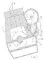
- Fig. 1 shows an internal combustion engine with six cylinders 1a arranged in a line, and indicated with broken lines in fig. 1.
- the engine comprises an engine block 1.
- the engine in fig. 1 is adapted to be mounted transversally in a vehicle, and fig. 1 shows a side of the engine, at which a transmission would be fitted.
- the longitudinal direction of the engine is defined as being parallel to the line of cylinders.
- the number of cylinders is not critical to the scope of the invention, i.e. the engine could include any number of cylinders, e.g. three, four or five.
- the engine comprises a crankshaft 2 and an additional shaft 3.
- the second gear 5 is adapted to rotate in relation to the additional shaft 3, but the latter is not adapted to rotate in relation to the engine block 1.
- the second gear could be fixed to the additional shaft 3, and the latter could be biased to the engine block 1 via bearings.
- the first gear 4 is located on one of the cheeks of a throw 6 of the crankshaft 2, and thus the first 4 and second 5 gear are located inside the engine block 1, between the ends of the crankshaft 2.
- the gear set 4, 5 can be located at any suitable place along the crankshaft 2.
- the second drive member 5 could be a sprocket driven indirectly via a belt or a chain.
- the engine block 1 comprises a first engine block part 7, a second engine block part 8, and a third engine block part 9.
- the first and second engine block parts 7, 8 are in contact with each other at a substantially flat plane of contact 10, being located at a distance from the crankshaft 2.
- the additional shaft 3 is positioned with its centerline essentially in the plane of contact 10 between the first and second engine block part 7, 8.
- the additional shaft 3 is used for transferring power to two camshafts 11, and other auxiliary devices in the form of a fuel pump 12 and an alternator 14.
- the camshafts 11 and the fuel pump 12 are indicated only with crosses and broken lines, respectively.
- the first further gear 16a is fixedly connected to the second gear 5.
- the second further drive member 16b is shown as being driven by the first further drive member 16a directly, but alternatively the second further drive member 16b could be a sprocket driven indirectly by means of a chain or a belt.
- the camshafts 11 are in turn driven by the synchronization shaft 15 via a chain transmission 17, located externally of the engine block 1.
- the fuel pump 12 is also driven by the synchronization shaft 15 via a chain transmission 18.
- the chain transmission 17, 18 for the camshafts 11 and the fuel pump 12 are located above a flywheel 18a of the engine, (see fig. 2).
- the flywheel 18a located longitudinally between a clutch 18c for the engine drive train and the cylinders, is at least partly housed in the engine block 1.
- the chain transmission 17 for the camshafts 11 and the chain transmission 18 for the fuel pump 12 are driven by the same shaft, i.e. the further shaft 15.
- the further shaft 15 could be replaced by two concentric shafts for driving the chain transmission 17 for the camshafts 11 and the chain transmission 18 for the fuel pump 12, respectively.
- an oil pump 13 is driven by a sprocket 19a, supported by the additional shaft 3 and fixedly connected to the second gear 5, and a chain transmission 19.
- the oil pump 13 is located in the second engine block part 8.
- a vacuum pump 19b is mounted externally onto the second engine block part 8, and driven by a cam 19c mounted on the oil pump axle (not shown).
- the oil pump 13 and the vacuum pump 19b can be mounted into and onto, respectively, the second engine block part 8 before the latter is mounted to the first engine block part 7. This will simplify the production of the engine.
- a fuel pump could be mounted onto the second engine block part 8 and driven by a cam 19c mounted on the oil pump axle.
- the oil pump 13 could be driven directly by the crankshaft via a gear set.
- the alternator 14 is driven via a gear 20, an alternator shaft 20a, and an alternator clutch 21, the gear 20 being driven by the second gear 5 on the additional shaft 3.
- the alternator shaft and the further shaft 15 are separate parts.
- the alternator 14 could be driven by the further shaft 15, whereby the gear 20 and the alternator shaft 20a could be omitted.
- the alternator 14 can be driven by a chain transmission from the additional shaft 3.
- additional auxiliary devices can be driven via a belt pulley 22 provided on the further shaft 15.
- the further shaft 15 could be replaced by two concentric shafts, one for driving the chain transmission 17 for the camshafts 11 and the chain transmission 18 for the fuel pump 12, and another for driving additional auxiliary devices via the belt pulley 22.
- the engine could be provided with one or more than two camshafts 11, adapted to be driven by the synchronization shaft 15.
- the auxiliary devices could be driven by other means than those mentioned above, e.g. using belt drives or gears instead of chain drives, or chain or belt drives instead of gears.
- the additional shaft 3 can be used for transferring power to other auxiliary devices than those mentioned above.
- the term auxiliary device includes any arrangement on the engine for supporting the process of driving the crankshaft by piston movements in the cylinders resulting from the combustion of the fuel and air mixture.
- auxiliary devices are water pump, engine fan, oil pump, vacuum pump, fuel pump and compressor.
- these examples are not exhaustive, and many other apparatuses or arrangements considered auxiliary devices within the scope of the claims below.
- the drive arrangements for the auxiliary devices are provided mainly on the side on the engine so that no parts of these extend significally beyond the engine block 1.
- the additional shaft 3 being positioned in the plane of contact 10 between the first and second engine block part 7, 8 allows for an easy process of installing the shaft 3 in the engine block 1, and thereby providing the bearings for the shaft 3.
- the plane of contact 10 between the first and second engine block part 7, 8 is oriented in an acute angle ⁇ to a cylinder bore direction, C, of the engine.
- the plane of contact 10 between the first and second engine block part 7, 8 could be oriented parallel or substantially parallel to the cylinder bore direction of the engine.
- the plane of contact 10 between the first and second engine block part 7, 8 could be oriented so that the angle ⁇ , as defined in fig. 1, is negative.
- the acute angle ⁇ , or the parallelism between the plane of contact 10 and the cylinder bore direction C provides for the freedom of the engine designer being extended further, since positioning of the additional shaft 3 could be made, in principle, at any vertical location along the plane of contact 10.
- the additional shaft 3 is located in a region above the crankshaft 2 and laterally of the cylinders 1a of the engine. This means that the additional shaft 3 with the second gear 5 adds to the width of the engine in a region above the region of the crankshaft 2.
- the region of the crankshaft 2 is usually a region where most inline engines have their greatest width.
- the additional shaft 3 being located in a region above the crankshaft 2 means that the overall width of the engine is less affected since the additional shaft 3 is located in a narrower region, closer to the cylinder head.
- the engine is adapted to be mounted in a vehicle so that the cylinder bores (C) are tilted in a direction opposite to the side on which the additional shaft 3 is located, so that the cylinder bore C direction forms an angle ⁇ to a vertical axis of the vehicle.
- the angle ⁇ is about 12°.
- the first and the third engine block part 7, 9 are in contact with each other at a substantially flat plane of contact 23.
- the crankshaft 2 is positioned with its centerline essentially in the plane of contact 23 between the first and third engine block part 7, 9.
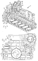
- the production of the internal combustion engine described above includes the steps described below:
- the production of the first, second and third engine block part 7, 8, 9 includes an individual casting process for each part.
- the first engine block part 7 is provided with a first flat surface 24 and a second flat surface 25
- the second engine block part 8 is provided with a flat surface 26
- the third engine block part 9 is provided with a flat surface 27.
- Dowel pins (not shown) are provided in a region which will include the plane of contact 10 between the two parts 7, 8.
- the second engine block part 8 is positioned adjacent to the first engine block part 7, whereby the flat surface 26 of the second engine block part 8 is pressed against the first flat surface 24 of the first engine block part 7, forming the plane of contact 10 between the two parts 7, 8.
- other means of positioning the parts in relation to each other can be provided.
- parts of a fastening arrangement including threaded holes for bolts 28, (see fig. 4), are formed so as to be aligned in the two adjacent parts 7, 8.
- the second engine block part 8 is then mounted to the first engine block part 7 by means of the fastening arrangement 28.
- the third engine block part 9 is positioned adjacent to the first engine block part 7, whereby the flat surface 27 of the third engine block part 9 is pressed against the second flat surface 25 of the first engine block part 7, forming the plane of contact 23 between the two parts 7, 8, (see fig. 5).
- parts of a fastening arrangement including threaded holes for bolts 29, (see fig. 4), are formed so as to be aligned in the two adjacent parts 7, 9, whereupon the third engine block part 9 is mounted to the first engine block part 7 by means of the fastening arrangement 29.
- a bore 30 for the crankshaft 2 is milled in the engine block 1, whereby the center line of the bore is positioned essentially in the plane of contact 23 between the first and third engine block part 7, 9.
- a bore 31 for the additional shaft 3 is milled in the engine block 1, whereby the center line of the bore is positioned essentially in the plane of contact 10 between the first and second engine block part 7, 8.
- the two bores 30, 31 are produced in the same production machine, so that the bore 31 for the additional shaft 3 is produced in the same engine production step as the bore 30 for the crankshaft 2. This makes it possible to obtain a very high precision regarding the distance and parallelism between the bores 30, 31 and hence the two shafts 2, 3.
- a bore 32 for the further shaft 15 is produced in the same production step as the bores 30, 31 for the camshaft 2 and additional shaft 3. This will make production more effective, and it will also secure a correct distance and parallelism between the additional shaft 3 and the further shaft 15. As a result less noise and a reduced risk of failure will be provided in connection to the gears 16a, 16b working between the additional shaft 3 and the further shaft 15.
- the second engine block part 8 is removed from the first engine block part 7, and the further shaft 15 with the second further gear 16b (see fig. 2), and other synchronization parts are mounted to the second engine block part, before the latter is mounted finally onto the first engine block part.
- synchronization parts 15, 16b will already be mounted in the second engine block part 8, and only the additional shaft 3 has to be fitted when the second engine block part 8 is finally mounted to the first engine block part 7.
- the oil pump 13 and the vacuum pump 19b can be mounted to the second engine block part 8 before mounting the latter to the first engine block part 7.
- the additional shaft 3 has been described as supporting gears to drive auxiliary devices, such as camshafts and fuel pump. However, the additional shaft 3 could also be used to drive other accessories of a vehicle, such as an air conditioning compressor.
- the additional shaft can also be connected to an engine transmission, whereby it is used for outputting the engine power to the transmission.
Landscapes
- Engineering & Computer Science (AREA)
- Chemical & Material Sciences (AREA)
- Combustion & Propulsion (AREA)
- Mechanical Engineering (AREA)
- General Engineering & Computer Science (AREA)
- Cylinder Crankcases Of Internal Combustion Engines (AREA)
Priority Applications (2)
| Application Number | Priority Date | Filing Date | Title |
|---|---|---|---|
| EP20030024732 EP1528236B1 (fr) | 2003-10-29 | 2003-10-29 | Moteur à combustion interne et procédé pour produire celui-ci |
| DE2003619385 DE60319385T2 (de) | 2003-10-29 | 2003-10-29 | Brennkraftmaschine und Verfahren zur Fertigung davon |
Applications Claiming Priority (1)
| Application Number | Priority Date | Filing Date | Title |
|---|---|---|---|
| EP20030024732 EP1528236B1 (fr) | 2003-10-29 | 2003-10-29 | Moteur à combustion interne et procédé pour produire celui-ci |
Publications (2)
| Publication Number | Publication Date |
|---|---|
| EP1528236A1 true EP1528236A1 (fr) | 2005-05-04 |
| EP1528236B1 EP1528236B1 (fr) | 2008-02-27 |
Family
ID=34400481
Family Applications (1)
| Application Number | Title | Priority Date | Filing Date |
|---|---|---|---|
| EP20030024732 Expired - Lifetime EP1528236B1 (fr) | 2003-10-29 | 2003-10-29 | Moteur à combustion interne et procédé pour produire celui-ci |
Country Status (2)
| Country | Link |
|---|---|
| EP (1) | EP1528236B1 (fr) |
| DE (1) | DE60319385T2 (fr) |
Families Citing this family (1)
| Publication number | Priority date | Publication date | Assignee | Title |
|---|---|---|---|---|
| JP6842342B2 (ja) * | 2017-03-30 | 2021-03-17 | 本田技研工業株式会社 | 内燃機関の駆動部構造 |
Citations (7)
| Publication number | Priority date | Publication date | Assignee | Title |
|---|---|---|---|---|
| US2553935A (en) * | 1948-04-17 | 1951-05-22 | F A Boucha | Method of manufacturing connecting rods |
| US4753199A (en) * | 1985-12-09 | 1988-06-28 | Avl Gesellschaft fur Verbrennungskraftmaschinen und Messtechnik m.b.H. Prof. Dr. Dr.h.c. Hans List | Internal combustion engine |
| DE3906991A1 (de) * | 1988-03-17 | 1989-10-05 | Volkswagen Ag | Nockenwellen-antriebsanordnung |
| US5063897A (en) * | 1989-07-06 | 1991-11-12 | Yamaha Hatsudoki Kabushiki Kaisha Yamaha Motor Co., Ltd. | Accessory drive arrangement for engine |
| US5873336A (en) * | 1996-09-11 | 1999-02-23 | Yamaha Hatsudoki Kabushiki Kaisha | Cam drive system for engine |
| US20010050193A1 (en) * | 2000-02-25 | 2001-12-13 | Suzuki Kabushiki Kaisha | Motorcycle |
| EP1279858A1 (fr) * | 2001-07-28 | 2003-01-29 | Cummins Engine Company, Ltd. | Ensemble d'arbre d'équilibrage |
-
2003
- 2003-10-29 DE DE2003619385 patent/DE60319385T2/de not_active Expired - Lifetime
- 2003-10-29 EP EP20030024732 patent/EP1528236B1/fr not_active Expired - Lifetime
Patent Citations (7)
| Publication number | Priority date | Publication date | Assignee | Title |
|---|---|---|---|---|
| US2553935A (en) * | 1948-04-17 | 1951-05-22 | F A Boucha | Method of manufacturing connecting rods |
| US4753199A (en) * | 1985-12-09 | 1988-06-28 | Avl Gesellschaft fur Verbrennungskraftmaschinen und Messtechnik m.b.H. Prof. Dr. Dr.h.c. Hans List | Internal combustion engine |
| DE3906991A1 (de) * | 1988-03-17 | 1989-10-05 | Volkswagen Ag | Nockenwellen-antriebsanordnung |
| US5063897A (en) * | 1989-07-06 | 1991-11-12 | Yamaha Hatsudoki Kabushiki Kaisha Yamaha Motor Co., Ltd. | Accessory drive arrangement for engine |
| US5873336A (en) * | 1996-09-11 | 1999-02-23 | Yamaha Hatsudoki Kabushiki Kaisha | Cam drive system for engine |
| US20010050193A1 (en) * | 2000-02-25 | 2001-12-13 | Suzuki Kabushiki Kaisha | Motorcycle |
| EP1279858A1 (fr) * | 2001-07-28 | 2003-01-29 | Cummins Engine Company, Ltd. | Ensemble d'arbre d'équilibrage |
Also Published As
| Publication number | Publication date |
|---|---|
| EP1528236B1 (fr) | 2008-02-27 |
| DE60319385D1 (de) | 2008-04-10 |
| DE60319385T2 (de) | 2009-03-19 |
Similar Documents
| Publication | Publication Date | Title |
|---|---|---|
| CN1230610C (zh) | 具有内燃机的改进型动力设备 | |
| EP1178193A2 (fr) | Moteur à combustion interne pour moto | |
| US8047176B2 (en) | Balancer apparatus for an engine | |
| US4589382A (en) | V-type multicylinder internal combustion engine | |
| US6718934B2 (en) | Balancer structure for a V-type engine | |
| JPH0932884A (ja) | 4サイクルエンジンのバランサー | |
| EP0754879B1 (fr) | Moteur à combustion interne avec système d'équilibrage | |
| EP1528236B1 (fr) | Moteur à combustion interne et procédé pour produire celui-ci | |
| JPH04209926A (ja) | 内燃機関の補機部品駆動装置 | |
| EP1512854B1 (fr) | Moteur à combustion interne avec les cylindres rangés en ligne | |
| JP4704242B2 (ja) | 排気浄化用二次空気供給装置 | |
| JP3633088B2 (ja) | エンジンの補機取付構造 | |
| US20240044286A1 (en) | Internal Combustion Engine Having Common Engine Parts And Method Of Forming Same | |
| JP4286438B2 (ja) | クランク軸ホルダ | |
| JPH0861081A (ja) | エンジンのタイミングチェーン装架装置 | |
| US9759098B1 (en) | Valvetrain conversion kit for an engine | |
| JP3657303B2 (ja) | エンジンの潤滑装置 | |
| JP4148814B2 (ja) | 内燃機関の潤滑装置 | |
| US20050229877A1 (en) | Dual overhead camshaft V-2 engine | |
| JPH11229888A (ja) | 歯車列内の中間歯車の支持構造 | |
| JPH05263654A (ja) | V型エンジンの構造 | |
| JP3516759B2 (ja) | エンジンの発電機配置構造 | |
| JPH0529772B2 (fr) | ||
| JP2025180258A (ja) | エンジン、及びエンジンの製造方法 | |
| WO2023047868A1 (fr) | Moteur à combustion interne |
Legal Events
| Date | Code | Title | Description |
|---|---|---|---|
| PUAI | Public reference made under article 153(3) epc to a published international application that has entered the european phase |
Free format text: ORIGINAL CODE: 0009012 |
|
| AK | Designated contracting states |
Kind code of ref document: A1 Designated state(s): AT BE BG CH CY CZ DE DK EE ES FI FR GB GR HU IE IT LI LU MC NL PT RO SE SI SK TR |
|
| AX | Request for extension of the european patent |
Extension state: AL LT LV MK |
|
| 17P | Request for examination filed |
Effective date: 20051102 |
|
| AKX | Designation fees paid |
Designated state(s): DE GB SE |
|
| GRAP | Despatch of communication of intention to grant a patent |
Free format text: ORIGINAL CODE: EPIDOSNIGR1 |
|
| GRAS | Grant fee paid |
Free format text: ORIGINAL CODE: EPIDOSNIGR3 |
|
| GRAA | (expected) grant |
Free format text: ORIGINAL CODE: 0009210 |
|
| RAP1 | Party data changed (applicant data changed or rights of an application transferred) |
Owner name: FORD GLOBAL TECHNOLOGIES, LLC |
|
| AK | Designated contracting states |
Kind code of ref document: B1 Designated state(s): DE GB SE |
|
| REG | Reference to a national code |
Ref country code: GB Ref legal event code: FG4D |
|
| REF | Corresponds to: |
Ref document number: 60319385 Country of ref document: DE Date of ref document: 20080410 Kind code of ref document: P |
|
| REG | Reference to a national code |
Ref country code: SE Ref legal event code: TRGR |
|
| PLBE | No opposition filed within time limit |
Free format text: ORIGINAL CODE: 0009261 |
|
| STAA | Information on the status of an ep patent application or granted ep patent |
Free format text: STATUS: NO OPPOSITION FILED WITHIN TIME LIMIT |
|
| 26N | No opposition filed |
Effective date: 20081128 |
|
| REG | Reference to a national code |
Ref country code: GB Ref legal event code: 732E Free format text: REGISTERED BETWEEN 20111020 AND 20111025 |
|
| REG | Reference to a national code |
Ref country code: DE Ref legal event code: R082 Ref document number: 60319385 Country of ref document: DE Representative=s name: HOFFMANN - EITLE, DE |
|
| REG | Reference to a national code |
Ref country code: DE Ref legal event code: R082 Ref document number: 60319385 Country of ref document: DE Representative=s name: HOFFMANN - EITLE, DE Effective date: 20120207 Ref country code: DE Ref legal event code: R081 Ref document number: 60319385 Country of ref document: DE Owner name: VOLVO CAR CORPORATION, SE Free format text: FORMER OWNER: FORD GLOBAL TECHNOLOGIES, LLC, DEARBORN, MICH., US Effective date: 20120207 Ref country code: DE Ref legal event code: R082 Ref document number: 60319385 Country of ref document: DE Representative=s name: HOFFMANN - EITLE PATENT- UND RECHTSANWAELTE PA, DE Effective date: 20120207 |
|
| PGFP | Annual fee paid to national office [announced via postgrant information from national office to epo] |
Ref country code: GB Payment date: 20141015 Year of fee payment: 12 Ref country code: SE Payment date: 20141027 Year of fee payment: 12 |
|
| REG | Reference to a national code |
Ref country code: SE Ref legal event code: EUG |
|
| GBPC | Gb: european patent ceased through non-payment of renewal fee |
Effective date: 20151029 |
|
| PG25 | Lapsed in a contracting state [announced via postgrant information from national office to epo] |
Ref country code: GB Free format text: LAPSE BECAUSE OF NON-PAYMENT OF DUE FEES Effective date: 20151029 |
|
| PG25 | Lapsed in a contracting state [announced via postgrant information from national office to epo] |
Ref country code: SE Free format text: LAPSE BECAUSE OF NON-PAYMENT OF DUE FEES Effective date: 20151030 |
|
| PGFP | Annual fee paid to national office [announced via postgrant information from national office to epo] |
Ref country code: DE Payment date: 20220920 Year of fee payment: 20 |
|
| REG | Reference to a national code |
Ref country code: DE Ref legal event code: R071 Ref document number: 60319385 Country of ref document: DE |