EP1528244A1 - Vorrichtung bestehend aus einem Zylinderkopf und dessen Abdeckung, an den Zylinderblock angebracht, zur Ölabscheidung der Verbrennungs- und Verdichtungs- Leckgase - Google Patents
Vorrichtung bestehend aus einem Zylinderkopf und dessen Abdeckung, an den Zylinderblock angebracht, zur Ölabscheidung der Verbrennungs- und Verdichtungs- Leckgase Download PDFInfo
- Publication number
- EP1528244A1 EP1528244A1 EP04292178A EP04292178A EP1528244A1 EP 1528244 A1 EP1528244 A1 EP 1528244A1 EP 04292178 A EP04292178 A EP 04292178A EP 04292178 A EP04292178 A EP 04292178A EP 1528244 A1 EP1528244 A1 EP 1528244A1
- Authority
- EP
- European Patent Office
- Prior art keywords
- cylinder head
- cover
- chamber
- gases
- oil
- Prior art date
- Legal status (The legal status is an assumption and is not a legal conclusion. Google has not performed a legal analysis and makes no representation as to the accuracy of the status listed.)
- Withdrawn
Links
Images


Classifications
-
- F—MECHANICAL ENGINEERING; LIGHTING; HEATING; WEAPONS; BLASTING
- F02—COMBUSTION ENGINES; HOT-GAS OR COMBUSTION-PRODUCT ENGINE PLANTS
- F02M—SUPPLYING COMBUSTION ENGINES IN GENERAL WITH COMBUSTIBLE MIXTURES OR CONSTITUENTS THEREOF
- F02M35/00—Combustion-air cleaners, air intakes, intake silencers, or induction systems specially adapted for, or arranged on, internal-combustion engines
- F02M35/10—Air intakes; Induction systems
- F02M35/10209—Fluid connections to the air intake system; their arrangement of pipes, valves or the like
- F02M35/10222—Exhaust gas recirculation [EGR]; Positive crankcase ventilation [PCV]; Additional air admission, lubricant or fuel vapour admission
-
- F—MECHANICAL ENGINEERING; LIGHTING; HEATING; WEAPONS; BLASTING
- F01—MACHINES OR ENGINES IN GENERAL; ENGINE PLANTS IN GENERAL; STEAM ENGINES
- F01M—LUBRICATING OF MACHINES OR ENGINES IN GENERAL; LUBRICATING INTERNAL COMBUSTION ENGINES; CRANKCASE VENTILATING
- F01M13/00—Crankcase ventilating or breathing
- F01M13/02—Crankcase ventilating or breathing by means of additional source of positive or negative pressure
- F01M13/021—Crankcase ventilating or breathing by means of additional source of positive or negative pressure of negative pressure
- F01M13/022—Crankcase ventilating or breathing by means of additional source of positive or negative pressure of negative pressure using engine inlet suction
-
- F—MECHANICAL ENGINEERING; LIGHTING; HEATING; WEAPONS; BLASTING
- F01—MACHINES OR ENGINES IN GENERAL; ENGINE PLANTS IN GENERAL; STEAM ENGINES
- F01M—LUBRICATING OF MACHINES OR ENGINES IN GENERAL; LUBRICATING INTERNAL COMBUSTION ENGINES; CRANKCASE VENTILATING
- F01M13/00—Crankcase ventilating or breathing
- F01M13/04—Crankcase ventilating or breathing having means for purifying air before leaving crankcase, e.g. removing oil
- F01M13/0416—Crankcase ventilating or breathing having means for purifying air before leaving crankcase, e.g. removing oil arranged in valve-covers
-
- F—MECHANICAL ENGINEERING; LIGHTING; HEATING; WEAPONS; BLASTING
- F01—MACHINES OR ENGINES IN GENERAL; ENGINE PLANTS IN GENERAL; STEAM ENGINES
- F01M—LUBRICATING OF MACHINES OR ENGINES IN GENERAL; LUBRICATING INTERNAL COMBUSTION ENGINES; CRANKCASE VENTILATING
- F01M13/00—Crankcase ventilating or breathing
- F01M13/04—Crankcase ventilating or breathing having means for purifying air before leaving crankcase, e.g. removing oil
- F01M2013/0461—Crankcase ventilating or breathing having means for purifying air before leaving crankcase, e.g. removing oil with a labyrinth
Definitions
- the invention relates to a device consisting of a cylinder head and its cover intended to be mounted on the engine block of an internal combustion engine.
- the device according to the invention which is consisting of a cylinder head and its lid intended for be mounted on the engine block of a combustion engine internal is characterized in that the cylinder head and its cover, integrated into these, of first passages to ensure, for lost gases loaded with oil and from combustion and compression, their circulation into a room top of camshaft housing breech of the engine and in which the gases are partially de-oiled by decantation, the oil decanted back down in the oil core of the cylinder head through holes in the part separating said core from the housing chamber of the camshaft, a pipe of passage in the cylinder head cover ensuring the circulation of partially de-oiled gases from the chamber housing the camshaft through a chamber the breech cover having therealong alternately opposite walls defining baffles or the like until completely de-oiled by decantation the gases arriving on a bottom wall of the cylinder head chamber located downstream of the baffles, decanted oil passing through this bottom wall to fall back into the chamber of housing of the camshaft, and in that the cover of cylinder head
- Figure 1 there is shown generally a view from above of the device according to the invention which has a cylinder head 1 and its associated plate 7. This figure thus described is in fact given only for show matches with cross sections Figures 2 to 8 and is therefore not further described.
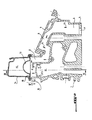
- a passage duct 13, also visible at the FIG. 3, formed in the breech cover 14 enables a rise according to the arrows F4 of the gases partially deoiled and brought into a settling chamber 15.
- This settling chamber formed in the lid head 14 has, as seen in Figure 3, alternately opposite walls defining baffles or the like 16 forming along this chamber a kind of labyrinth.
- the passage of gases according to the arrow F5 in the settling chamber 15 allows these gas, following the path of this kind of labyrinth, to be completely deoiled, the oil being deposited then in the bottom 17 of the cylinder head cover 14 downstream of baffles 16 and passing through the volume of chamber 9 of Figure 2 by orifices 18 formed in this bottom.
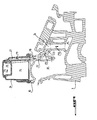
- the deoiled gases cross, according to the arrow F9, a bore 23 formed in the cylinder head 1 and pass into a channel 24 by following the arrow F10 to feed a hollow foundry cavity 25 formed by coring directly to the molding of the engine block in accordance with first method of forming part of the channels according to the invention and which is illustrated in FIGS. 4 and 5.
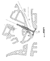
- the distribution of gases deoiled is done in intake ducts 27 in from the cavity 25 of Figure 4 and, according to Figure 7, this distribution is done in ducts intake 27 from the bore 26 of FIG.
- the distribution is then ensured, according to the method chosen, either by the length of the borehole 26 or by the the length of the gross foundry cavity 25 and by orifices or channels 29 (FIGS. 5 and 7) opening downstream of the intake valve 31.
- FIGS. 7, on the one hand, and 8, on the other hand, which both correspond to the audit second process, show two different implantations of the part of the channels for supplying the de-oiled gases level of the intake valve 31.
- Figure 7 shows an implementation of the canal "behind" the inlet valve 31, that is to say in downstream of the intake duct 27.
- This implantation corresponds to the preferred embodiment.
- the area on which the gases deoiled from channel 29 downstream of the valve intake 31 is a zone with greater turbulence and allows a better distribution of gases in the air intake.
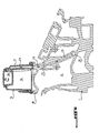
- Figure 8 shows on the contrary an implementation of channel "in front of" the intake valve 31.
- This channel is here referenced 32 and corresponds to channel 29 of FIG. by being in correspondence with a borehole 33 similar to drilling 26 of this last figure.
- holes or ducts such as 21, 22, 23, 26, 29, 32 and 33 can be made by drilling, drilling, pin demolding or sand core in the mold.
Landscapes
- Engineering & Computer Science (AREA)
- Mechanical Engineering (AREA)
- General Engineering & Computer Science (AREA)
- Chemical & Material Sciences (AREA)
- Combustion & Propulsion (AREA)
- Cylinder Crankcases Of Internal Combustion Engines (AREA)
- Lubrication Details And Ventilation Of Internal Combustion Engines (AREA)
Applications Claiming Priority (2)
| Application Number | Priority Date | Filing Date | Title |
|---|---|---|---|
| FR0312598A FR2861430B1 (fr) | 2003-10-28 | 2003-10-28 | Dispositif constitue d'une culasse et de son couvercle montes sur le bloc moteur pour le deshuilage des gaz perdus issus de la combustion et de la compression. |
| FR0312598 | 2003-10-28 |
Publications (1)
| Publication Number | Publication Date |
|---|---|
| EP1528244A1 true EP1528244A1 (de) | 2005-05-04 |
Family
ID=34400851
Family Applications (1)
| Application Number | Title | Priority Date | Filing Date |
|---|---|---|---|
| EP04292178A Withdrawn EP1528244A1 (de) | 2003-10-28 | 2004-09-10 | Vorrichtung bestehend aus einem Zylinderkopf und dessen Abdeckung, an den Zylinderblock angebracht, zur Ölabscheidung der Verbrennungs- und Verdichtungs- Leckgase |
Country Status (3)
| Country | Link |
|---|---|
| US (1) | US7143754B2 (de) |
| EP (1) | EP1528244A1 (de) |
| FR (1) | FR2861430B1 (de) |
Cited By (7)
| Publication number | Priority date | Publication date | Assignee | Title |
|---|---|---|---|---|
| EP1959105A1 (de) * | 2007-02-19 | 2008-08-20 | Bayerische Motorenwerke Aktiengesellschaft | Kurbelgehäuseentlüftung für eine Brennkraftmaschine |
| FR2949362A1 (fr) * | 2009-09-02 | 2011-03-04 | Peugeot Citroen Automobiles Sa | Procede de fabrication d'une piece metallique par moulage a modele perdu et culasse obtenue par ledit procede |
| EP2532850A1 (de) * | 2011-06-08 | 2012-12-12 | MAHLE Filter Systems Japan Corporation | Ölabscheider eines Verbrennungsmotors |
| CN109098817A (zh) * | 2018-09-14 | 2018-12-28 | 广西玉柴机器股份有限公司 | 一种滤板油驱式自适应调压发动机油气分离装置 |
| CN109139188A (zh) * | 2018-09-14 | 2019-01-04 | 广西玉柴机器股份有限公司 | 一种滤板气驱式自适应调压发动机油气分离装置 |
| CN109209563A (zh) * | 2018-09-14 | 2019-01-15 | 广西玉柴机器股份有限公司 | 一种滤板式发动机油气分离装置 |
| CN109209562A (zh) * | 2018-09-14 | 2019-01-15 | 广西玉柴机器股份有限公司 | 一种滤板气驱式发动机油气分离装置 |
Families Citing this family (9)
| Publication number | Priority date | Publication date | Assignee | Title |
|---|---|---|---|---|
| JP4321606B2 (ja) * | 2007-02-28 | 2009-08-26 | トヨタ自動車株式会社 | ブローバイガス還元装置及びそのブローバイガス還元装置に使用されるシリンダヘッド並びにそのブローバイガス還元装置を備えた内燃機関 |
| US20090056668A1 (en) * | 2007-09-05 | 2009-03-05 | Gm Global Technology Operations, Inc. | Acoustic Side Cover for an Engine |
| US7770692B2 (en) * | 2007-09-14 | 2010-08-10 | Gm Global Technology Operations, Inc. | Engine acoustic treatment |
| JP2010096154A (ja) * | 2008-10-20 | 2010-04-30 | Aichi Mach Ind Co Ltd | 気液分離構造 |
| US8047186B2 (en) * | 2008-11-24 | 2011-11-01 | Toyota Motor Engineering & Manufacturing North America, Inc. | Oil separator |
| FR2958335B1 (fr) * | 2010-03-31 | 2013-03-15 | Peugeot Citroen Automobiles Sa | Culasse integrant un repartiteur de gaz de bas moteur recycles |
| CN103758655B (zh) * | 2014-01-27 | 2016-04-13 | 山东华盛中天工程机械有限责任公司 | 内置油气分离装置的发动机缸盖 |
| US9556767B2 (en) * | 2014-08-12 | 2017-01-31 | Ford Global Technologies, Llc | Intake manifold ports and PCV passages integrated into cam cover |
| CN106224053B (zh) * | 2016-07-26 | 2019-02-15 | 隆鑫通用动力股份有限公司 | 发动机缸头盖总成及其发动机 |
Citations (6)
| Publication number | Priority date | Publication date | Assignee | Title |
|---|---|---|---|---|
| US4667647A (en) * | 1984-03-15 | 1987-05-26 | Honda Giken Kogyo Kabushiki Kaisha | Crankcase ventilating system and method of removing oil mist from gas in the system |
| DE3704567A1 (de) * | 1987-02-13 | 1988-08-25 | Kloeckner Humboldt Deutz Ag | Rueckfuehrleitung fuer leckgase aus dem kurbelgehaeuse |
| EP0454512A1 (de) * | 1990-04-26 | 1991-10-30 | Automobiles Peugeot | Reinigungs- und Rezirkulationseinrichtung für die Durchblasgase einer Brennkraftmaschine und Brennkraftmaschine ausgerüstet mit dieser Einrichtung |
| US5307784A (en) * | 1993-04-05 | 1994-05-03 | Ford Motor Company | Induction system for internal combustion engine |
| EP1227237A1 (de) * | 2001-01-25 | 2002-07-31 | Renault | Zylinderkopf für eine Brennkraftmaschine mit einem Ventilierungskanal |
| US20030150437A1 (en) * | 2002-02-08 | 2003-08-14 | Keiichi Nakamizo | Breathing device for internal combustion engine |
-
2003
- 2003-10-28 FR FR0312598A patent/FR2861430B1/fr not_active Expired - Fee Related
-
2004
- 2004-09-10 EP EP04292178A patent/EP1528244A1/de not_active Withdrawn
- 2004-10-20 US US10/968,356 patent/US7143754B2/en not_active Expired - Fee Related
Patent Citations (6)
| Publication number | Priority date | Publication date | Assignee | Title |
|---|---|---|---|---|
| US4667647A (en) * | 1984-03-15 | 1987-05-26 | Honda Giken Kogyo Kabushiki Kaisha | Crankcase ventilating system and method of removing oil mist from gas in the system |
| DE3704567A1 (de) * | 1987-02-13 | 1988-08-25 | Kloeckner Humboldt Deutz Ag | Rueckfuehrleitung fuer leckgase aus dem kurbelgehaeuse |
| EP0454512A1 (de) * | 1990-04-26 | 1991-10-30 | Automobiles Peugeot | Reinigungs- und Rezirkulationseinrichtung für die Durchblasgase einer Brennkraftmaschine und Brennkraftmaschine ausgerüstet mit dieser Einrichtung |
| US5307784A (en) * | 1993-04-05 | 1994-05-03 | Ford Motor Company | Induction system for internal combustion engine |
| EP1227237A1 (de) * | 2001-01-25 | 2002-07-31 | Renault | Zylinderkopf für eine Brennkraftmaschine mit einem Ventilierungskanal |
| US20030150437A1 (en) * | 2002-02-08 | 2003-08-14 | Keiichi Nakamizo | Breathing device for internal combustion engine |
Cited By (8)
| Publication number | Priority date | Publication date | Assignee | Title |
|---|---|---|---|---|
| EP1959105A1 (de) * | 2007-02-19 | 2008-08-20 | Bayerische Motorenwerke Aktiengesellschaft | Kurbelgehäuseentlüftung für eine Brennkraftmaschine |
| FR2949362A1 (fr) * | 2009-09-02 | 2011-03-04 | Peugeot Citroen Automobiles Sa | Procede de fabrication d'une piece metallique par moulage a modele perdu et culasse obtenue par ledit procede |
| EP2532850A1 (de) * | 2011-06-08 | 2012-12-12 | MAHLE Filter Systems Japan Corporation | Ölabscheider eines Verbrennungsmotors |
| US8794221B2 (en) | 2011-06-08 | 2014-08-05 | Mahle Filter Systems Japan Corporation | Oil separator of internal combustion engine |
| CN109098817A (zh) * | 2018-09-14 | 2018-12-28 | 广西玉柴机器股份有限公司 | 一种滤板油驱式自适应调压发动机油气分离装置 |
| CN109139188A (zh) * | 2018-09-14 | 2019-01-04 | 广西玉柴机器股份有限公司 | 一种滤板气驱式自适应调压发动机油气分离装置 |
| CN109209563A (zh) * | 2018-09-14 | 2019-01-15 | 广西玉柴机器股份有限公司 | 一种滤板式发动机油气分离装置 |
| CN109209562A (zh) * | 2018-09-14 | 2019-01-15 | 广西玉柴机器股份有限公司 | 一种滤板气驱式发动机油气分离装置 |
Also Published As
| Publication number | Publication date |
|---|---|
| US7143754B2 (en) | 2006-12-05 |
| FR2861430A1 (fr) | 2005-04-29 |
| US20050092268A1 (en) | 2005-05-05 |
| FR2861430B1 (fr) | 2006-02-10 |
Similar Documents
| Publication | Publication Date | Title |
|---|---|---|
| EP1528244A1 (de) | Vorrichtung bestehend aus einem Zylinderkopf und dessen Abdeckung, an den Zylinderblock angebracht, zur Ölabscheidung der Verbrennungs- und Verdichtungs- Leckgase | |
| EP0448431B1 (de) | Einlass- und Ölabscheidevorrichtung für eine Brennkraftmaschine und Maschine versehen mit dieser Vorrichtung | |
| US9017120B2 (en) | Outboard motor and watercraft including the same | |
| FR2486152A1 (fr) | Moteur a combustion interne a refroidissement par l'huile | |
| FR2745603A1 (fr) | Systeme de ventilation du compartiment du vilebrequin pour un moteur a combustion interne | |
| FR2574855A1 (fr) | Agencement pour le traitement de gaz de fuite dans un moteur a combustion interne pour vehicule automobile | |
| EP1859129B1 (de) | Ölzirkulationsvorrichtung für verbrennungsmotor | |
| KR20090048497A (ko) | 내연기관용 크랭크케이스 | |
| FR2661455A1 (fr) | Dispositif de recuperation et de recyclage des gaz de combustion imbrules emanant du carter d'un moteur a combustion interne, et moteur equipe de ce dispositif. | |
| FR2958335A1 (fr) | Culasse integrant un repartiteur de gaz de bas moteur recycles | |
| EP0628704B1 (de) | Wiederverwendungsvorrichtung von Schmiermittel in einer Brennkraftmaschine | |
| CN101135264B (zh) | 具有改进的旁通管的两冲程发动机 | |
| FR2626621A1 (fr) | Dispositif de recyclage de carburant residuel pour moteur a combustion interne | |
| KR200153736Y1 (ko) | 로커 커버의 필러 캡 구조 | |
| KR100559662B1 (ko) | 블로바이 가스 환원장치 | |
| FR2948967A1 (fr) | Architecture de traitement des gaz de carter dans un moteur a combustion interne d'un vehicule automobile. | |
| EP0688944B1 (de) | Zweitaktbrennkraftmaschine | |
| EP3056697B1 (de) | Vorrichtung und verfahren zur reinigung eines ansaugkreislaufs von gasen, die aus einem gehäuse austreten | |
| JP5679949B2 (ja) | 過給機付エンジンの吸気通路内オイル排出装置 | |
| JP5652290B2 (ja) | 内燃機関のブローバイガス処理装置 | |
| KR20060006480A (ko) | 에어 인테이크 시스템 | |
| FR2774129A1 (fr) | Dispositif de reaspiration des gaz de carter d'un moteur a combustion interne | |
| EP1965044A2 (de) | Verbrennungsmotor, der mit einer Belüftungsvorrichtung ausgestattet ist | |
| FR2991719A1 (fr) | Procede de balayage des gaz brules redisuels par double levee de soupapes pour un moteur a deux temps notamment de type diesel | |
| FR2857412A1 (fr) | Culasse a conduit incline et moule pour une telle culasse |
Legal Events
| Date | Code | Title | Description |
|---|---|---|---|
| PUAI | Public reference made under article 153(3) epc to a published international application that has entered the european phase |
Free format text: ORIGINAL CODE: 0009012 |
|
| AK | Designated contracting states |
Kind code of ref document: A1 Designated state(s): AT BE BG CH CY CZ DE DK EE ES FI FR GB GR HU IE IT LI LU MC NL PL PT RO SE SI SK TR |
|
| AX | Request for extension of the european patent |
Extension state: AL HR LT LV MK |
|
| 17P | Request for examination filed |
Effective date: 20051007 |
|
| AKX | Designation fees paid |
Designated state(s): AT BE BG CH CY CZ DE DK EE ES FI FR GB GR HU IE IT LI LU MC NL PL PT RO SE SI SK TR |
|
| GRAP | Despatch of communication of intention to grant a patent |
Free format text: ORIGINAL CODE: EPIDOSNIGR1 |
|
| STAA | Information on the status of an ep patent application or granted ep patent |
Free format text: STATUS: THE APPLICATION IS DEEMED TO BE WITHDRAWN |
|
| 18D | Application deemed to be withdrawn |
Effective date: 20100331 |