EP0454512A1 - Reinigungs- und Rezirkulationseinrichtung für die Durchblasgase einer Brennkraftmaschine und Brennkraftmaschine ausgerüstet mit dieser Einrichtung - Google Patents
Reinigungs- und Rezirkulationseinrichtung für die Durchblasgase einer Brennkraftmaschine und Brennkraftmaschine ausgerüstet mit dieser Einrichtung Download PDFInfo
- Publication number
- EP0454512A1 EP0454512A1 EP91400757A EP91400757A EP0454512A1 EP 0454512 A1 EP0454512 A1 EP 0454512A1 EP 91400757 A EP91400757 A EP 91400757A EP 91400757 A EP91400757 A EP 91400757A EP 0454512 A1 EP0454512 A1 EP 0454512A1
- Authority
- EP
- European Patent Office
- Prior art keywords
- cylinder head
- chamber
- internal combustion
- engine
- head cover
- Prior art date
- Legal status (The legal status is an assumption and is not a legal conclusion. Google has not performed a legal analysis and makes no representation as to the accuracy of the status listed.)
- Granted
Links
Images


Classifications
-
- F—MECHANICAL ENGINEERING; LIGHTING; HEATING; WEAPONS; BLASTING
- F02—COMBUSTION ENGINES; HOT-GAS OR COMBUSTION-PRODUCT ENGINE PLANTS
- F02F—CYLINDERS, PISTONS OR CASINGS, FOR COMBUSTION ENGINES; ARRANGEMENTS OF SEALINGS IN COMBUSTION ENGINES
- F02F7/00—Casings, e.g. crankcases
-
- F—MECHANICAL ENGINEERING; LIGHTING; HEATING; WEAPONS; BLASTING
- F01—MACHINES OR ENGINES IN GENERAL; ENGINE PLANTS IN GENERAL; STEAM ENGINES
- F01M—LUBRICATING OF MACHINES OR ENGINES IN GENERAL; LUBRICATING INTERNAL COMBUSTION ENGINES; CRANKCASE VENTILATING
- F01M13/00—Crankcase ventilating or breathing
- F01M13/04—Crankcase ventilating or breathing having means for purifying air before leaving crankcase, e.g. removing oil
- F01M13/0416—Crankcase ventilating or breathing having means for purifying air before leaving crankcase, e.g. removing oil arranged in valve-covers
-
- F—MECHANICAL ENGINEERING; LIGHTING; HEATING; WEAPONS; BLASTING
- F02—COMBUSTION ENGINES; HOT-GAS OR COMBUSTION-PRODUCT ENGINE PLANTS
- F02B—INTERNAL-COMBUSTION PISTON ENGINES; COMBUSTION ENGINES IN GENERAL
- F02B2275/00—Other engines, components or details, not provided for in other groups of this subclass
- F02B2275/18—DOHC [Double overhead camshaft]
-
- F—MECHANICAL ENGINEERING; LIGHTING; HEATING; WEAPONS; BLASTING
- F02—COMBUSTION ENGINES; HOT-GAS OR COMBUSTION-PRODUCT ENGINE PLANTS
- F02F—CYLINDERS, PISTONS OR CASINGS, FOR COMBUSTION ENGINES; ARRANGEMENTS OF SEALINGS IN COMBUSTION ENGINES
- F02F7/00—Casings, e.g. crankcases
- F02F7/006—Camshaft or pushrod housings
Definitions
- the present invention aims to remedy these drawbacks in particular by proposing an improved recovery and recycling device and making it possible to avoid mounting a sheet of complex shape in the settling chamber, and which is consequently less expensive and technically simpler. With such a device, it is also possible to avoid any vibration generating noise during engine operation.
- the foundry of the cylinder head has a wall located in the joint plane of the cylinder head and of the cylinder head cover, which wall constitutes the bottom wall of the chamber above and is pierced with openings for the passage of unburnt combustion gases and for discharging the oil.
- the foundry of the cylinder head cover forms a substantially U-shaped cross section conduit whose end of the branches bears on the aforementioned bottom wall, and which extends in a closed loop in substantially the joint plane of the cylinder head and the cylinder head cover.
- the aforementioned conduit comprises baffles coming from molding with the cylinder head cover.
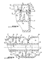
- Figure 2 is a partial sectional view of the engine, along a sectional plane passing through the axes of the rods of two valves of a cylinder of this engine.
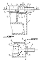
- FIG. 5 is a sectional view of the engine, along the line V-V of FIG. 4.
- the cylinder head cover 6 has an upper wall 16 from which two substantially parallel walls or partitions 36 project.
Landscapes
- Engineering & Computer Science (AREA)
- Mechanical Engineering (AREA)
- General Engineering & Computer Science (AREA)
- Chemical & Material Sciences (AREA)
- Combustion & Propulsion (AREA)
- Lubrication Details And Ventilation Of Internal Combustion Engines (AREA)
- Cylinder Crankcases Of Internal Combustion Engines (AREA)
Applications Claiming Priority (2)
| Application Number | Priority Date | Filing Date | Title |
|---|---|---|---|
| FR9005329 | 1990-04-26 | ||
| FR9005329A FR2661455A1 (fr) | 1990-04-26 | 1990-04-26 | Dispositif de recuperation et de recyclage des gaz de combustion imbrules emanant du carter d'un moteur a combustion interne, et moteur equipe de ce dispositif. |
Publications (2)
| Publication Number | Publication Date |
|---|---|
| EP0454512A1 true EP0454512A1 (de) | 1991-10-30 |
| EP0454512B1 EP0454512B1 (de) | 1992-12-30 |
Family
ID=9396117
Family Applications (1)
| Application Number | Title | Priority Date | Filing Date |
|---|---|---|---|
| EP19910400757 Expired - Lifetime EP0454512B1 (de) | 1990-04-26 | 1991-03-20 | Reinigungs- und Rezirkulationseinrichtung für die Durchblasgase einer Brennkraftmaschine und Brennkraftmaschine ausgerüstet mit dieser Einrichtung |
Country Status (3)
| Country | Link |
|---|---|
| EP (1) | EP0454512B1 (de) |
| DE (1) | DE69100016T2 (de) |
| FR (1) | FR2661455A1 (de) |
Cited By (8)
| Publication number | Priority date | Publication date | Assignee | Title |
|---|---|---|---|---|
| EP0856644A1 (de) * | 1997-02-01 | 1998-08-05 | Daimler-Benz Aktiengesellschaft | Entlüftungsvorrichtung für ein Kurbelgehäuse einer Brennkraftmaschine |
| EP0911496A1 (de) * | 1997-10-22 | 1999-04-28 | Honda Giken Kogyo Kabushiki Kaisha | Entlüftungsvorrichtung einer Brennkraftmaschine |
| FR2774129A1 (fr) * | 1998-01-23 | 1999-07-30 | Renault | Dispositif de reaspiration des gaz de carter d'un moteur a combustion interne |
| FR2819856A1 (fr) * | 2001-01-25 | 2002-07-26 | Renault | Culasse de moteur thermique comportant un canal d'acheminement moule |
| WO2005024192A1 (de) * | 2003-09-06 | 2005-03-17 | Fev Motorentechnik Gmbh | Mehrzylinder-kolbenbrennkraftmaschine mit ölabscheidung für abgesaugtes blow-by gas |
| FR2861430A1 (fr) * | 2003-10-28 | 2005-04-29 | Peugeot Citroen Automobiles Sa | Dispositif constitue d'une culasse et de son couvercle montes sur le bloc moteur pour le deshuilage des gaz perdus issus de la combustion et de la compression. |
| EP2299100A1 (de) | 2009-09-04 | 2011-03-23 | Mark IV Systèmes Moteurs | Saugrohr mit integrierter Kurbelgehäuseentlüftung und Fahrzeug mit einem solchen Saugrohr |
| US10968796B2 (en) | 2018-07-23 | 2021-04-06 | Honda Motor Co., Ltd. | Breather structure of engine |
Families Citing this family (2)
| Publication number | Priority date | Publication date | Assignee | Title |
|---|---|---|---|---|
| DE19937033A1 (de) * | 1999-08-05 | 2001-02-08 | Volkswagen Ag | Entlüftungsvorrichtung für ein Kurbelgehäuse einer Brennkraftmaschine |
| DE102004041110B4 (de) * | 2004-08-24 | 2018-12-20 | Mahle Filtersysteme Gmbh | Brennkraftmaschine und zugehörige Zylinderkopfhaube |
Citations (5)
| Publication number | Priority date | Publication date | Assignee | Title |
|---|---|---|---|---|
| US2844130A (en) * | 1956-11-05 | 1958-07-22 | Deere Mfg Co | Internal-combustion engine |
| GB966168A (en) * | 1962-04-25 | 1964-08-06 | Daimler Benz Ag | Improvements relating to cylinder heads for internal combustion engines |
| DE3618557A1 (de) * | 1985-06-03 | 1986-12-04 | Honda Giken Kogyo K.K., Tokio/Tokyo | Durchblasgas-rezirkulationseinrichtung |
| US4723529A (en) * | 1985-07-19 | 1988-02-09 | Toyota Jidosha Kabushiki Kaisha | Oil separator for a blowby gas ventilation system of an internal combustion engine |
| FR2613420A1 (fr) * | 1987-03-30 | 1988-10-07 | Suzuki Motor Co | Dispositif reniflard et dispositif de reglage de tendeur de chaine de distribution de moteur a quatre temps |
-
1990
- 1990-04-26 FR FR9005329A patent/FR2661455A1/fr active Granted
-
1991
- 1991-03-20 DE DE1991600016 patent/DE69100016T2/de not_active Expired - Fee Related
- 1991-03-20 EP EP19910400757 patent/EP0454512B1/de not_active Expired - Lifetime
Patent Citations (5)
| Publication number | Priority date | Publication date | Assignee | Title |
|---|---|---|---|---|
| US2844130A (en) * | 1956-11-05 | 1958-07-22 | Deere Mfg Co | Internal-combustion engine |
| GB966168A (en) * | 1962-04-25 | 1964-08-06 | Daimler Benz Ag | Improvements relating to cylinder heads for internal combustion engines |
| DE3618557A1 (de) * | 1985-06-03 | 1986-12-04 | Honda Giken Kogyo K.K., Tokio/Tokyo | Durchblasgas-rezirkulationseinrichtung |
| US4723529A (en) * | 1985-07-19 | 1988-02-09 | Toyota Jidosha Kabushiki Kaisha | Oil separator for a blowby gas ventilation system of an internal combustion engine |
| FR2613420A1 (fr) * | 1987-03-30 | 1988-10-07 | Suzuki Motor Co | Dispositif reniflard et dispositif de reglage de tendeur de chaine de distribution de moteur a quatre temps |
Cited By (13)
| Publication number | Priority date | Publication date | Assignee | Title |
|---|---|---|---|---|
| EP0856644A1 (de) * | 1997-02-01 | 1998-08-05 | Daimler-Benz Aktiengesellschaft | Entlüftungsvorrichtung für ein Kurbelgehäuse einer Brennkraftmaschine |
| US5975065A (en) * | 1997-02-01 | 1999-11-02 | Daimler Chrysler Ag | Venting arrangement for an internal combustion engine |
| EP0911496A1 (de) * | 1997-10-22 | 1999-04-28 | Honda Giken Kogyo Kabushiki Kaisha | Entlüftungsvorrichtung einer Brennkraftmaschine |
| US6021766A (en) * | 1997-10-22 | 2000-02-08 | Honda Giken Kogyo Kabushiki Kaisha | Breather device for engine |
| FR2774129A1 (fr) * | 1998-01-23 | 1999-07-30 | Renault | Dispositif de reaspiration des gaz de carter d'un moteur a combustion interne |
| EP1227237A1 (de) * | 2001-01-25 | 2002-07-31 | Renault | Zylinderkopf für eine Brennkraftmaschine mit einem Ventilierungskanal |
| FR2819856A1 (fr) * | 2001-01-25 | 2002-07-26 | Renault | Culasse de moteur thermique comportant un canal d'acheminement moule |
| WO2005024192A1 (de) * | 2003-09-06 | 2005-03-17 | Fev Motorentechnik Gmbh | Mehrzylinder-kolbenbrennkraftmaschine mit ölabscheidung für abgesaugtes blow-by gas |
| FR2861430A1 (fr) * | 2003-10-28 | 2005-04-29 | Peugeot Citroen Automobiles Sa | Dispositif constitue d'une culasse et de son couvercle montes sur le bloc moteur pour le deshuilage des gaz perdus issus de la combustion et de la compression. |
| EP1528244A1 (de) * | 2003-10-28 | 2005-05-04 | Peugeot Citroen Automobiles S.A. | Vorrichtung bestehend aus einem Zylinderkopf und dessen Abdeckung, an den Zylinderblock angebracht, zur Ölabscheidung der Verbrennungs- und Verdichtungs- Leckgase |
| US7143754B2 (en) | 2003-10-28 | 2006-12-05 | Peugeot Citroen Automobiles S.A. | Device comprising a cylinder head and its cover, mounted on the engine block, for de-oiling of waste gases from combustion and compression |
| EP2299100A1 (de) | 2009-09-04 | 2011-03-23 | Mark IV Systèmes Moteurs | Saugrohr mit integrierter Kurbelgehäuseentlüftung und Fahrzeug mit einem solchen Saugrohr |
| US10968796B2 (en) | 2018-07-23 | 2021-04-06 | Honda Motor Co., Ltd. | Breather structure of engine |
Also Published As
| Publication number | Publication date |
|---|---|
| DE69100016D1 (de) | 1993-02-11 |
| FR2661455A1 (fr) | 1991-10-31 |
| FR2661455B1 (de) | 1994-08-19 |
| DE69100016T2 (de) | 1993-05-27 |
| EP0454512B1 (de) | 1992-12-30 |
Similar Documents
| Publication | Publication Date | Title |
|---|---|---|
| EP0454512B1 (de) | Reinigungs- und Rezirkulationseinrichtung für die Durchblasgase einer Brennkraftmaschine und Brennkraftmaschine ausgerüstet mit dieser Einrichtung | |
| FR2758365A3 (fr) | Ventilation de carter de vilebrequin a fonctions complementaires integrees | |
| US10344640B2 (en) | Oil strainer support structure for internal combustion engine | |
| FR2826691A1 (fr) | Circuit de reaspiration des gaz de carter d'un moteur a combustion interne | |
| WO2006027469A1 (fr) | Deshuileur pour moteur a combustion interne | |
| JP4393718B2 (ja) | V型内燃機関 | |
| FR2776017A1 (fr) | Moteur a combustion interne comportant un dispositif anti-barbotage | |
| FR2639089A1 (fr) | Carter d'huile en alliage leger pour moteur a combustion interne | |
| FR2789125A1 (fr) | Dispositif de reaspiration des gaz de carter d'un moteur | |
| FR2860548A1 (fr) | Crepine d'alimentation pour pompe a l'huile | |
| EP0846223B1 (de) | Ansaugkrümmer für brennkraftmaschine | |
| EP0391014B1 (de) | Absorptions-Schalldämpfer für Brennkraftmaschinen, insbesondere für Geländefahrzeuge | |
| EP2108790B1 (de) | Ölnebelabscheidevorrichtung mit einem Filtermedium zur Kurbelraumentlüftung. | |
| EP1484480B1 (de) | Elastischer Ölwanneneinsatz | |
| JP2003247468A (ja) | 複数気筒エンジンの吸気装置 | |
| EP1905971A2 (de) | Vorrichtung zur Trennung bestimmter Stoffe, die von einem Verbrennungsmotor produziert werden | |
| FR3140912A1 (fr) | Appareil de travail à guidage manuel et pot amortisseur pour son moteur à combustion interne | |
| FR2985769A1 (fr) | Bloc-moteur d'un moteur a combustion interne | |
| EP2512620A1 (de) | Recyclingfähiges partikelfilter | |
| FR2755180A1 (fr) | Dispositif de reniflard pour le carter de vilebrequin d'un moteur a combustion interne | |
| FR2745335A1 (fr) | Dispositif de ventilation pour carter de moteur a combustion interne | |
| FR2774129A1 (fr) | Dispositif de reaspiration des gaz de carter d'un moteur a combustion interne | |
| EP2299100B1 (de) | Saugrohr mit integrierter Kurbelgehäuseentlüftung und Fahrzeug mit einem solchen Saugrohr | |
| FR2733799A1 (fr) | Element de circuit d'admission d'air pour moteur a combustion interne | |
| FR2914012A1 (fr) | Dispositif de ventilation d'un moteur a combustion interne dote d'un systeme anti-retour d'huile |
Legal Events
| Date | Code | Title | Description |
|---|---|---|---|
| PUAI | Public reference made under article 153(3) epc to a published international application that has entered the european phase |
Free format text: ORIGINAL CODE: 0009012 |
|
| AK | Designated contracting states |
Kind code of ref document: A1 Designated state(s): DE GB IT |
|
| 17P | Request for examination filed |
Effective date: 19911219 |
|
| 17Q | First examination report despatched |
Effective date: 19920422 |
|
| GRAA | (expected) grant |
Free format text: ORIGINAL CODE: 0009210 |
|
| AK | Designated contracting states |
Kind code of ref document: B1 Designated state(s): DE GB IT |
|
| REF | Corresponds to: |
Ref document number: 69100016 Country of ref document: DE Date of ref document: 19930211 |
|
| ITF | It: translation for a ep patent filed | ||
| GBT | Gb: translation of ep patent filed (gb section 77(6)(a)/1977) |
Effective date: 19930405 |
|
| PLBE | No opposition filed within time limit |
Free format text: ORIGINAL CODE: 0009261 |
|
| STAA | Information on the status of an ep patent application or granted ep patent |
Free format text: STATUS: NO OPPOSITION FILED WITHIN TIME LIMIT |
|
| 26N | No opposition filed | ||
| PGFP | Annual fee paid to national office [announced via postgrant information from national office to epo] |
Ref country code: GB Payment date: 19950310 Year of fee payment: 5 |
|
| PGFP | Annual fee paid to national office [announced via postgrant information from national office to epo] |
Ref country code: DE Payment date: 19950322 Year of fee payment: 5 |
|
| PG25 | Lapsed in a contracting state [announced via postgrant information from national office to epo] |
Ref country code: GB Effective date: 19960320 |
|
| GBPC | Gb: european patent ceased through non-payment of renewal fee |
Effective date: 19960320 |
|
| PG25 | Lapsed in a contracting state [announced via postgrant information from national office to epo] |
Ref country code: DE Effective date: 19961203 |
|
| PG25 | Lapsed in a contracting state [announced via postgrant information from national office to epo] |
Ref country code: IT Free format text: LAPSE BECAUSE OF NON-PAYMENT OF DUE FEES;WARNING: LAPSES OF ITALIAN PATENTS WITH EFFECTIVE DATE BEFORE 2007 MAY HAVE OCCURRED AT ANY TIME BEFORE 2007. THE CORRECT EFFECTIVE DATE MAY BE DIFFERENT FROM THE ONE RECORDED. Effective date: 20050320 |