EP1528551A2 - Appareil à disque pourvu d' un dispositif de serrage d'épaisseur mince - Google Patents
Appareil à disque pourvu d' un dispositif de serrage d'épaisseur mince Download PDFInfo
- Publication number
- EP1528551A2 EP1528551A2 EP04025349A EP04025349A EP1528551A2 EP 1528551 A2 EP1528551 A2 EP 1528551A2 EP 04025349 A EP04025349 A EP 04025349A EP 04025349 A EP04025349 A EP 04025349A EP 1528551 A2 EP1528551 A2 EP 1528551A2
- Authority
- EP
- European Patent Office
- Prior art keywords
- clamper
- plate
- disk
- turntable
- outer ring
- Prior art date
- Legal status (The legal status is an assumption and is not a legal conclusion. Google has not performed a legal analysis and makes no representation as to the accuracy of the status listed.)
- Withdrawn
Links
Images


Classifications
-
- G—PHYSICS
- G11—INFORMATION STORAGE
- G11B—INFORMATION STORAGE BASED ON RELATIVE MOVEMENT BETWEEN RECORD CARRIER AND TRANSDUCER
- G11B17/00—Guiding record carriers not specifically of filamentary or web form, or of supports therefor
- G11B17/02—Details
- G11B17/022—Positioning or locking of single discs
- G11B17/028—Positioning or locking of single discs of discs rotating during transducing operation
- G11B17/0284—Positioning or locking of single discs of discs rotating during transducing operation by clampers
Definitions
- the present invention relates to a disk device in which a clamper to be used in clamping a disk mounted on a turntable is reduced in thickness.
- a disk device reads signals recorded in a disk using an optical pickup.
- the disk is mounted on a turntable and clamped to rotate such that the optical pickup moves in a radial direction at a predetermined velocity. Since the turntable is directly connected to a spindle of a drive motor and rotates at a high velocity, if the disk is simply placed on the turntable and a hole in the center of the disk is fitted with a projection in the center of the turntable, the disk comes off during rotation or slippage occurs between the disk and the turntable to cause phase change in an angular velocity. Thus, in order to prevent such problems, the disk is clamped.
- a clamper of a clamp mechanism is axially supported so as to rotate freely and rotates with the turntable.
- the clamper can rotate while clamping the disk mounted on the turntable.
- a mechanism utilizing attraction of a magnet is adopted as clamp means of the clamper.
- a magnetic substance to be attracted by the magnet is provided on the turntable side.
- the disk mounted on the turntable can rotate at a predetermined velocity without coming off by being clamped, a positional relation between the clamper and the turntable has to be accurate. If an unbalanced load occurs in the turntable or the clamper, unevenness in rotation and vibration are caused. When the disk is clamped utilizing attraction of the magnet, if there is backlash in a mechanism for holding the magnet, a position of the clamper with respect to the turntable deviates following the rotation of the disk.
- the chucking device includes: a center guide locked by a chucking holding member provided on a chassis side and holds the recording disk between a turntable for driving to rotate the disk and the center guide; and a yoke plate that is attached to the center guide and becomes a path for a magnet, which is magnetically coupled with a magnetic substance provided on the turntable, and a magnetic flux.
- the yoke plate (clamper plate) includes: an opening to be used for locking to a chucking holding section of the center guide and in which locking pieces formed at one end of the center guide fit to attach the yoke plate to the center guide; and a projection for making it impossible to attach the yoke plate from an opposite direction.
- a disk device equipped with a thin damper comprises a turntable and a clamper in which a disk is mounted on the turntable and pressed and clamped by the clamper, wherein the clamper including a clamper body integrally formed of synthetic resin, a magnet, and a clamper plate made of a metal magnetic substance, the clamper body having a disc-like clamp section to press the disk, a cylindrical, center guide forming a housing space for the magnet in a center thereof, a cylindrical outer ring erected from the damp section, and locking pieces extending to inward from an upper part of the outer ring so as not to project over an upper end of the outer ring and an upper end of the center guide and being arranged at equal intervals in two or more places, and the clamper plate having hooks extending below to engage with the locking pieces respectively.
- the clamper including a clamper body integrally formed of synthetic resin, a magnet, and a clamper plate made of a metal magnetic substance, the clamper body having a disc-like clamp section to press the
- the outer ring may have stoppers extending vertically on an inner surface thereof near one end of the respective locking pieces, whereby rotation of the clamper plate in one direction can be prevented. Conversely, stoppers may be provided in the respective hooks to prevent the rotation of the clamper plate in one direction.
- the locking pieces for attaching the clamper plate do not project on the upper surface of the clamper plate, thickness of the clamper is reduced so much more for that, and reduction in thickness of the disk device can be realized.
- Fig. 1 shows a state in which a disk 2 mounted on a tumtable 1 is damped by a clamper 3 in a disk device according to an embodiment of the invention.
- the turntable 1 is attached to a spindle 4a of a motor 4 so as to be driven to rotate freely.
- a protrusion 1 a projecting upward is formed in the center of the disc-like turntable 1, and a recess 1 b is formed in the center of an upper surface of the protrusion 1a.
- a magnetic substance 5 is attached in a donut-like groove formed in a peripheral part of the recess 1 b.
- a through-hole is formed in the center of the disk 2.
- the protrusion 1 a in the center of the turntable 1 fits in the through-hole, whereby the disk 2 is mounted in a fixed position on the turntable 1 correctly.
- a clamper body 10 is integrally formed of a synthetic resin material and includes a substantially disc-like clamp section 11 and a cylindrical center guide 12 in the center.
- a bottom plate 13 is formed in the center on the inner side of the center guide 12.
- a donut-like housing space 15 for housing a magnet 6 is formed between the cylindrical projection 13a and the center guide 12.
- a convex ring 14 is provided on the bottom surface side of the clamp section 11 concentrically with the boss 13b.
- a substantially cylindrical outer ring 16 is formed in the clamp section 11, which is erected on a concentric circle of the center guide 12.
- Locking pieces 17 are provided in three places at an upper end of the outer ring 16 at equal intervals extending horizontally to the inside.
- the locking pieces 17 are formed such that upper surfaces thereof are in positions lower than the upper end of the outer ring 16.
- the upper surfaces of the locking pieces 17 must not project higher than at least the upper end of the outer ring 16.
- Stoppers 18 extending vertically are provided near one-end sides of the respective locking pieces 17 on an inner side surface of the outer ring 16.
- the upper end of the outer ring 16 is formed at height identical with height of the upper end position of the center guide 12.
- a clamper plate 20 to be described later is placed on the outer ring 16 and the center guide 12.
- the ring-shaped magnet 6 is housed in the housing space 15 in the cylindrical center guide 12 provided in the center of the damper body 10, and the clamper plate 20 is attached so as to prevent the magnet 6 from coming off.
- the clamper plate 20 is a plate obtained by punching a metal magnetic substance such as an iron plate.
- the clamper plate 20 has a center hole 21 in the center of a circular plate. Cutout holes 22 are formed in three places corresponding to the locking pieces 17 at equal intervals with the center hole 21 as a center.
- L-shaped hooks 23 extending outward from the inside are formed in the respective cutout holes 22.
- the hooks 23 bend to extend to the lower side of the cutout holes 22 such that upper surfaces of the hooks 23 engage with lower surfaces of the locking pieces 17 (see Fig. 3(b)).
- Fig. 4 shows an assembly procedure for a clamper.
- the magnet 6 is housed in the housing space 15 of the clamper body 10, and the clamper plate 20 is attached over the magnet 6.
- the clamper plate 20 is placed on the outer ring 16 such that the hooks 23 are located in positions beside the locking pieces 17 where the stoppers 18 are not set.
- the hooks 23 are placed so as to fit in the inside of the outer ring 16 and to be located between the respective locking pieces 17 (see Fig. 5(a)).
- Fig. 6 shows a state in which the clamper plate 20 is attached to the clamper body 10.
- the hook 23 is locked under the locking piece 17 extending horizontally to the inside from the outer ring 16, and the locking piece 17 does not project on the upper surface of the clamper plate 20.
- the clamper plate 23 touches the stoppers 18 and never comes off.
- stoppers 18 are provided on the clamper body 10 side in this embodiment, stoppers may be formed in the hooks 23 on the clamper plate 23 side.
- the hooks 23 are made excellent in a spring property and locked by the locking pieces 17 with an increased frictional force to obtain a locked state that does not require the stoppers 18.
- Figs. 7(a), 7(b) and 7(c) show another embodiment of the clamper plate 20.
- the clamper plate 20 in this embodiment identical with the clamper plate 20 shown in Figs. 3(a), 3(b) and 3(c) except that plural small protrusions 24 are provided on the lower surface of the clamper plate 20 near the outer periphery thereof.
- the protrusions 24 are provided at equal intervals with the center hole 21 as a center.
- the clamper plate 20 is punched from a metal plate by a mold. However, burrs are caused on a punched surface and come into contact with a clamper support section provided in a cabinet to form shavings. The shavings may contaminate the inside of an apparatus as a foreign substance. In addition, contact sound is caused when the clamper plate comes into contact with the clamper support section. Therefore, the protrusions 24, which are higher than the burrs caused on the punched surface, are press-molded.
- the number of protrusions is not specifically limited and a shape thereof is arbitrary as long as the burrs do not come into contact with a clamper support section 30.
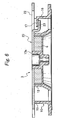
- Fig. 8 shows a state in which the clamper body 10 is supported by the clamper support section 30.
- the protrusions 24 formed on the lower surface of the damper plate 20 are in contact with the clamper support section 30.
- small burrs 20b are caused on a punched surface 20a of the clamper plate 20, the burrs 2b never come into contact with the clamper support section 30.
- the clamper plate 20 is constituted as described above, the clamper plate 20 can be attached with a one-touch operation, and a thin clamper is realized while the locking pieces 17 do not project above the clamper plate 20.
Landscapes
- Holding Or Fastening Of Disk On Rotational Shaft (AREA)
Applications Claiming Priority (4)
| Application Number | Priority Date | Filing Date | Title |
|---|---|---|---|
| JP2003370195 | 2003-10-30 | ||
| JP2003370195 | 2003-10-30 | ||
| JP2004080214 | 2004-03-19 | ||
| JP2004080214A JP2005158212A (ja) | 2003-10-30 | 2004-03-19 | 薄型クランパーを備えたディスク装置 |
Publications (1)
| Publication Number | Publication Date |
|---|---|
| EP1528551A2 true EP1528551A2 (fr) | 2005-05-04 |
Family
ID=34425409
Family Applications (1)
| Application Number | Title | Priority Date | Filing Date |
|---|---|---|---|
| EP04025349A Withdrawn EP1528551A2 (fr) | 2003-10-30 | 2004-10-25 | Appareil à disque pourvu d' un dispositif de serrage d'épaisseur mince |
Country Status (3)
| Country | Link |
|---|---|
| US (1) | US20050097589A1 (fr) |
| EP (1) | EP1528551A2 (fr) |
| JP (1) | JP2005158212A (fr) |
Cited By (1)
| Publication number | Priority date | Publication date | Assignee | Title |
|---|---|---|---|---|
| US7409697B2 (en) | 2004-11-24 | 2008-08-05 | Orion Electric Co., Ltd. | Electronic apparatus including disk device |
Families Citing this family (6)
| Publication number | Priority date | Publication date | Assignee | Title |
|---|---|---|---|---|
| JP2008511944A (ja) * | 2004-09-02 | 2008-04-17 | コーニンクレッカ フィリップス エレクトロニクス エヌ ヴィ | ディスクドライブユニット |
| JP2007066429A (ja) * | 2005-08-31 | 2007-03-15 | Orion Denki Kk | 記録/再生装置のクランパ及び該クランパを備えた記録/再生装置 |
| US8146116B2 (en) * | 2006-11-15 | 2012-03-27 | Panasonic Corporation | Disk device having a clamper restricting member |
| KR20120082199A (ko) | 2011-01-13 | 2012-07-23 | 엘지이노텍 주식회사 | 스핀들 모터용 턴 테이블 및 이를 갖는 스핀들 모터 |
| JP2012243370A (ja) * | 2011-05-23 | 2012-12-10 | Nippon Densan Corp | モータおよびディスク駆動装置 |
| JP5423730B2 (ja) * | 2011-06-16 | 2014-02-19 | 船井電機株式会社 | 光ディスク装置 |
Family Cites Families (4)
| Publication number | Priority date | Publication date | Assignee | Title |
|---|---|---|---|---|
| JPH10283703A (ja) * | 1997-04-02 | 1998-10-23 | Mitsumi Electric Co Ltd | ディスククランパ及び前記ディスククランパを備えたディスク駆動装置 |
| TW522390B (en) * | 1998-07-09 | 2003-03-01 | Ind Tech Res Inst | Magnet-floating auto-elevating disk clamper tool |
| JP3578334B2 (ja) * | 2000-10-12 | 2004-10-20 | 船井電機株式会社 | ディスクプレーヤーのチャッキング装置 |
| TW591625B (en) * | 2002-01-15 | 2004-06-11 | Benq Corp | Apparatus for reducing tray-in noise |
-
2004
- 2004-03-19 JP JP2004080214A patent/JP2005158212A/ja active Pending
- 2004-10-25 EP EP04025349A patent/EP1528551A2/fr not_active Withdrawn
- 2004-10-28 US US10/974,674 patent/US20050097589A1/en not_active Abandoned
Cited By (1)
| Publication number | Priority date | Publication date | Assignee | Title |
|---|---|---|---|---|
| US7409697B2 (en) | 2004-11-24 | 2008-08-05 | Orion Electric Co., Ltd. | Electronic apparatus including disk device |
Also Published As
| Publication number | Publication date |
|---|---|
| US20050097589A1 (en) | 2005-05-05 |
| JP2005158212A (ja) | 2005-06-16 |
Similar Documents
| Publication | Publication Date | Title |
|---|---|---|
| US4730300A (en) | Disc centering device for a disc playback device | |
| CN110323910B (zh) | 线性致动器 | |
| KR900004661B1 (ko) | 정보처리장치 | |
| KR20090122329A (ko) | 척킹장치 및 이 척킹장치를 탑재한 브러시리스 모터 및 디스크 구동 장치 | |
| EP1528551A2 (fr) | Appareil à disque pourvu d' un dispositif de serrage d'épaisseur mince | |
| US4734813A (en) | Clamper holding mechanism for positioning an information recording disk | |
| JP3848159B2 (ja) | ディスク保持機構およびディスク保持機構のクランパー | |
| KR101091345B1 (ko) | 척 부재를 포함한 스핀들 모터 | |
| CN100385545C (zh) | 夹持器和使用该夹持器的盘驱动装置 | |
| US6292456B1 (en) | Apparatus for activating a disk clamper by magnetic restoring force | |
| EP0660320A2 (fr) | Plateau d'un tourne-disques pour disque compact et minidisc | |
| US20050071862A1 (en) | Disk device having clamp mechanism | |
| US6532205B2 (en) | Disk centering apparatus | |
| JP3059729U (ja) | 円盤状記録ディスクのチャッキング装置 | |
| JPH09106600A (ja) | コンパクトディスクプレーヤーのディスクチャッキング装置 | |
| KR0135015Y1 (ko) | 컴팩트 디스크 플레이어의 클램프 고정장치 | |
| JP3458504B2 (ja) | ディスクカートリッジ | |
| JP2004030744A (ja) | スピンドルモータのクランプ機構 | |
| JPH0765471A (ja) | ディスク駆動装置 | |
| JP2000163837A (ja) | ディスクのクランプ装置 | |
| JP2004079111A (ja) | ターンテーブルとクランパからなるディスククランプ機構 | |
| US20110145845A1 (en) | Disk device | |
| JP2000100034A (ja) | ディスクチャッキング機構 | |
| JP2012104176A (ja) | チャッキング装置、モータ、およびディスク駆動装置 | |
| KR980008459A (ko) | 액츄에이터의 픽업 커버 조립지그 |
Legal Events
| Date | Code | Title | Description |
|---|---|---|---|
| PUAI | Public reference made under article 153(3) epc to a published international application that has entered the european phase |
Free format text: ORIGINAL CODE: 0009012 |
|
| AK | Designated contracting states |
Kind code of ref document: A2 Designated state(s): AT BE BG CH CY CZ DE DK EE ES FI FR GB GR HU IE IT LI LU MC NL PL PT RO SE SI SK TR |
|
| AX | Request for extension of the european patent |
Extension state: AL HR LT LV MK |
|
| STAA | Information on the status of an ep patent application or granted ep patent |
Free format text: STATUS: THE APPLICATION HAS BEEN WITHDRAWN |
|
| 18W | Application withdrawn |
Effective date: 20070820 |