EP1528639B1 - Boîtier de connecteur ayant un pont de court-circuit - Google Patents
Boîtier de connecteur ayant un pont de court-circuit Download PDFInfo
- Publication number
- EP1528639B1 EP1528639B1 EP04017808A EP04017808A EP1528639B1 EP 1528639 B1 EP1528639 B1 EP 1528639B1 EP 04017808 A EP04017808 A EP 04017808A EP 04017808 A EP04017808 A EP 04017808A EP 1528639 B1 EP1528639 B1 EP 1528639B1
- Authority
- EP
- European Patent Office
- Prior art keywords
- contact
- connector
- longitudinal axis
- housing
- connector housing
- Prior art date
- Legal status (The legal status is an assumption and is not a legal conclusion. Google has not performed a legal analysis and makes no representation as to the accuracy of the status listed.)
- Expired - Lifetime
Links
- 230000013011 mating Effects 0.000 claims description 15
- 238000003780 insertion Methods 0.000 claims description 11
- 230000037431 insertion Effects 0.000 claims description 11
- 230000004308 accommodation Effects 0.000 claims description 7
- 239000004020 conductor Substances 0.000 claims description 3
- 230000000717 retained effect Effects 0.000 claims 1
- 238000009423 ventilation Methods 0.000 description 5
- 241000047428 Halter Species 0.000 description 4
- 238000005452 bending Methods 0.000 description 2
- 230000002349 favourable effect Effects 0.000 description 2
- 239000000463 material Substances 0.000 description 2
- RYGMFSIKBFXOCR-UHFFFAOYSA-N Copper Chemical compound [Cu] RYGMFSIKBFXOCR-UHFFFAOYSA-N 0.000 description 1
- 239000011248 coating agent Substances 0.000 description 1
- 238000000576 coating method Methods 0.000 description 1
- 238000004891 communication Methods 0.000 description 1
- 229910052802 copper Inorganic materials 0.000 description 1
- 239000010949 copper Substances 0.000 description 1
- 239000012777 electrically insulating material Substances 0.000 description 1
- 230000003100 immobilizing effect Effects 0.000 description 1
- 238000011144 upstream manufacturing Methods 0.000 description 1
Images


Classifications
-
- H—ELECTRICITY
- H01—ELECTRIC ELEMENTS
- H01R—ELECTRICALLY-CONDUCTIVE CONNECTIONS; STRUCTURAL ASSOCIATIONS OF A PLURALITY OF MUTUALLY-INSULATED ELECTRICAL CONNECTING ELEMENTS; COUPLING DEVICES; CURRENT COLLECTORS
- H01R13/00—Details of coupling devices of the kinds covered by groups H01R12/70 or H01R24/00 - H01R33/00
- H01R13/66—Structural association with built-in electrical component
- H01R13/70—Structural association with built-in electrical component with built-in switch
- H01R13/701—Structural association with built-in electrical component with built-in switch the switch being actuated by an accessory, e.g. cover, locking member
-
- H—ELECTRICITY
- H01—ELECTRIC ELEMENTS
- H01R—ELECTRICALLY-CONDUCTIVE CONNECTIONS; STRUCTURAL ASSOCIATIONS OF A PLURALITY OF MUTUALLY-INSULATED ELECTRICAL CONNECTING ELEMENTS; COUPLING DEVICES; CURRENT COLLECTORS
- H01R13/00—Details of coupling devices of the kinds covered by groups H01R12/70 or H01R24/00 - H01R33/00
- H01R13/40—Securing contact members in or to a base or case; Insulating of contact members
- H01R13/42—Securing in a demountable manner
- H01R13/422—Securing in resilient one-piece base or case, e.g. by friction; One-piece base or case formed with resilient locking means
- H01R13/4223—Securing in resilient one-piece base or case, e.g. by friction; One-piece base or case formed with resilient locking means comprising integral flexible contact retaining fingers
-
- H—ELECTRICITY
- H01—ELECTRIC ELEMENTS
- H01R—ELECTRICALLY-CONDUCTIVE CONNECTIONS; STRUCTURAL ASSOCIATIONS OF A PLURALITY OF MUTUALLY-INSULATED ELECTRICAL CONNECTING ELEMENTS; COUPLING DEVICES; CURRENT COLLECTORS
- H01R13/00—Details of coupling devices of the kinds covered by groups H01R12/70 or H01R24/00 - H01R33/00
- H01R13/40—Securing contact members in or to a base or case; Insulating of contact members
- H01R13/42—Securing in a demountable manner
- H01R13/436—Securing a plurality of contact members by one locking piece or operation
- H01R13/4364—Insertion of locking piece from the front
- H01R13/4365—Insertion of locking piece from the front comprising a temporary and a final locking position
Definitions
- the invention relates to a connector housing comprising a longitudinal axis, a first housing portion having a front end face and a rear end, at least two receiving chambers extending parallel to the longitudinal axis for receiving an electrical contact element having a pin, wherein the receiving chambers each have an insertion opening for the associated contact element and having an open end face for the front end opening for the plug pin, an elastic latch arm per receiving chamber for fixing the contact element in the receiving chamber, a second housing portion which is integrally formed with the first housing portion forms a receiving space into which a portion of a housing of a mating connector can be introduced, which has a contact socket having contact elements, which are each electrically conductively connected to the contact elements and a plug connection comprising the Ste connector housing and an associated mating connector. More particularly, the invention relates to a connector housing having a shorting bridge for shorting the contact elements provided with a pin.
- EP 1 235 306 A2 describes such a connector housing with receiving chambers for contact elements with contact sockets, wherein the contact sockets are inserted through an insertion opening into the receiving chambers and via an opening in the front end face of the connector housing for the entry of a Connector pin are accessible.
- the contact elements are each set in the receiving chambers by a locking arm, which engages behind an edge on the associated contact element.
- a front holder is provided which enters into a gap between a wall of the first housing portion of the connector housing and the outer surface of the locking arms, so that they are fixed.
- the problem is that when inserting the contact element in the associated receiving chamber, the contact arms of the shorting bridge are in the rebounded state and thus are in the range of motion exiting the end face of the housing connector pins, so that the risk of misalignment of the contact element is.
- a special coating is provided on the connector pins to improve contact, damage to the surface of the connector pins may occur during the relative movement between the connector pins and the contact region of the contact arms.
- the expended for the assembly of the contact elements force is correspondingly high, since the spring force of the contact arms is overcome.
- the contact elements are made of a highly conductive material, for example, a copper material that is relatively soft, the connector pins can be bent.
- a connector housing in which a fuse element is provided which forms a secondary latch for both contact elements and for the shorting bridge in the connector housing.
- This element can be inserted transversely to the longitudinal axis into a recess of the connector housing and can be fixed in two different positions via latching means. In the first position, this securing element is held so that both the contact elements and the shorting bridge can be inserted into the connector housing so that they are fixed by the locking means provided in the connector housing. Thereafter, the securing element can be transferred to the final holding position, in which it secures both the shorting bridge and the individual contact elements in addition, so that a total of a double lock given is.
- a locking element in the form of a flap is provided, which is pivotally mounted on the connector housing and having first locking means which come into contact with second locking means on the mating connector and lock the connector housing to the mating connector.
- This locking flap is additionally provided with a release element that brings the shorting bridge out of contact with the contact elements in the locked state of the locking flap with the mating connector.
- the invention is therefore an object of the invention to provide a connector housing in which the contact elements are easy to assemble and the risk of damage to the same is not given despite the presence of a shorting bridge.
- An advantage of this design is that the known in itself for the setting of locking arms front holder can be additionally used to hold the contact arms of the shorting bridge initially in a raised release position during assembly of the contact elements, so that they are not connected to the plug pins Contact elements can come into contact. As a result, the assembly of the contact elements is facilitated overall. The insertion thus needs to be done only by overcoming the spring force of the locking arm. The plug pins themselves are not loaded at the tip when exiting the outlet opening in the end face of the first housing section, so that no damage can occur.
- the front holder can be transferred to its end position, so that the contact arms are released and are introduced transversely to the longitudinal axis of the connector pins.
- the contact arms of the shorting bridge contact the connector pins in a region close to the support, so that there is no risk of bending them.
- the front holder is designed like a frame and is at least partially sunk in the end position in the end position.
- a connector comprising a connector housing according to one of the claims, which relate to the connector housing, and a mating connector, which is associated with at least a second L comparativelement which brings the contact arms when connecting to the connector housing out of contact with the connector pins.
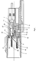
- a connector housing 2 can be seen, which has the longitudinal axis 1.
- the connector housing 2 comprises a first housing section 3 and a second housing section 4.
- the first housing section 3 extends between a front end face 5 and a rear end 6.
- two receiving chambers 7 are arranged, as in the present embodiment, a bipolar embodiment.
- the two receiving chambers 7 are parallel to the longitudinal axis, but only one of which is visible.
- the second receiving chamber is located behind the visible receiving chamber 7, ie behind the drawing plane.
- the receiving chamber 7 is open via an insertion 9 and an outlet bore 8 to the rear end 6.
- an outlet opening 10 is present, which is in communication with the receiving chamber 7.
- a locking arm 11 is provided per receiving chamber 7, which is integrally formed with the first housing portion 3, but is separated from it so that it can be elastically deformed. It has a locking projection 12 which, in the relaxed state of the locking arm 11, that is, when no force is exerted on it, protrudes into the region of the receiving chamber 7. Between the outer surfaces 15 of the locking arms 11 and the wall 14 of the first housing portion 3, a gap 13 is formed, in which the locking arm 11 can be elastically displaced.
- the first housing section 3 integrally formed second housing portion 4 forms a receiving space 16 for a housing portion of a mating connector.
- This receiving space 16 is arranged upstream of the front end face 5 of the first housing section 3.
- a fixing set 17 is provided transversely to the longitudinal axis 1 and offset thereto, on which the holding section of an electrically conductive shorting bridge 18 is accommodated.
- the setting approach 17 is over the front end surface 5 in the receiving space 16 before, and extends substantially parallel to the longitudinal axis 1.
- the shorting bridge 18 has in the proposed two-pole embodiment, two contact arms 19, of which only one can be seen.
- the second contact arm 19 is located in the plane behind the visible contact arm 19 and is spaced therefrom, so that both can spring separately.
- each contact arm 19 extends in the direction of the front end face 5 into a recess in the end face 5, and that the longitudinal axis 1 approximately , and has towards the free end a projection 19a and a again away from the longitudinal axis 1 portion.
- the connector housing 2 is associated with a front holder 20 which is located in the receiving space 16 in the initial position.
- the front holder 20 has two first vent elements 22. These each have an in the direction of the rear end 6 obliquely to the longitudinal axis 1 to be extended Lvid Chemistry 22a and then a holding surface 22b.
- the front holder 20 has struts 23 which extend from its front, designed as a frame 24 portion in the direction of the rear end 6 and carry a transversely to the longitudinal axis 1 extending cross member 22.
- the front holder 20 is made of an electrically insulating material.
- the first louver elements 22 each contact one of the contact arms 19 with the projection 19a provided in the region of the outwardly angled gate and lift the contact arms 19 on further insertion of the holder 20 in the direction of the rear end 6 by sliding the lugs 19a of the contact arms 19 on the ventilation surfaces 22a, so that they are supported in a direction transverse to the longitudinal axis 1 clearly outside the outlet openings 10 in the front end face 5 on the support surfaces 22b adjoining the ventilation surfaces 22a.
- the front holder 20 remains until complete assembly of contact elements 25, which are each connected to a cable 28.
- the insertion of the contact elements 25 takes place through the outlet bore 8 via the insertion opening 9 in the receiving chamber 7, wherein the elastic locking arm 11 with his Bolt projection 12 is displaced from the region of the receiving chamber 7 in the gap 13.
- the molded-in plug pin 26 passes through the outlet opening 10 outwards into the receiving space 16 via the front end face 5. Since the contact arms 19 are held away from the exit openings 10 by the front holder 20, the insertion can be done easily and without a frictional contact or a bending stress by the contact arms 19.
- the elastically deformed locking arm 11 can again assume its relaxed position, in which its locking projection 12 sits in front of a retaining edge 27 of the contact element 25.
- a seal 29 is arranged between the cable 28 and the wall of the outlet bore 8, to achieve a water- and moisture-proof connection.
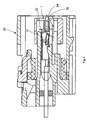
- the front holder 20 When all the contact elements 25 are inserted as described above and secured by the associated latch arms 11 in the receiving chambers 7, the front holder 20 can be moved along the longitudinal axis 1 towards the rear end 6, wherein the first Lsymmetricetti 22 come out of contact with the contact arms 19 and the cross member 24 enters the gap 13 between the wall 14 of the first housing portion 3 and the outer surface 15 of the locking arms 11, so that the gap 13 is filled in a direction transverse to the longitudinal axis 1. As a result, the locking arms 11 are fixed in their locked position. In this case, the front holder 20 assumes the position shown in Fig. 2, wherein the frame portion of the holder 20 is received in the recess 21 of the end face 5, so that it does not project beyond the front end face 5. From Fig. 2 is further seen that the contact arms 19 have come into contact with the connector pins 26 of the contact elements 25.
- the front holder 20 is shown as a single part, which comprises a in the end position in the recess 21 entering frame portion and extending parallel to the longitudinal axis 1 struts 23 which project from the frame portion and carry at its free ends the cross member 24 which runs transversely to the longitudinal axis 1.
- the first vent elements 22 can be seen, which are each provided with a vent surface 22a and a holding surface 22b.
- a mating connector 30 is shown having a portion 31, which enters the receiving space 16 of the connector housing 2 when connecting both together.
- this section 31 are also receiving chambers in which, however, are designed as contact sockets 32 designed contact elements.
- the mating connector 30 is associated with a second L separatedelement 33, that an obliquely from the longitudinal axis 1 is removed sliding surface 34 which comes into contact with the outwardly angled arm portions of the contact arms 19 of the shorting bridge 18 during insertion of the portion 31 in the receiving space 16, so that the contact arms 19 are lifted from the connector pins 26 from the position shown in Fig. 2, before the connector pins 26 can electrically conductively come into contact with the contact sockets 32.
- the short-circuiting bridge 18 may also has a corresponding number of contact arms 19. Furthermore, if a plurality of parallel rows of receiving chambers 7 are provided, a corresponding number of short-circuiting bridges 18 may be provided.
Landscapes
- Connector Housings Or Holding Contact Members (AREA)
Claims (6)
- Boîtier de connecteur enfichable (2) comprenant- un axe longitudinal (1),- un premier tronçon de boîtier (3) équipé- d'une surface frontale antérieure (5) et d'une extrémité postérieure (6),- au moins deux chambres de réception (7) s'étendant parallèlement à l'axe longitudinal (1) en vue de la réception respective d'un élément de contact électrique (25), présentant une fiche (26), les chambres de réception (7) présentant respectivement une ouverture d'introduction (9) pour l'élément de contact associé (25) et une ouverture de sortie (10) pour la fiche (26) ouverte sur la surface frontale antérieure (5),- un bras de verrouillage élastique (11) pour chaque chambre de réception (7) en vue de la fixation de l'élément de contact (25) dans la chambre de réception (7),- un second tronçon de boîtier (4), qui- fait corps avec le premier tronçon de boîtier (3),- forme un espace de réception (16), dans lequel peut être introduit un tronçon d'un boîtier d'un connecteur enfichable antagoniste (30), qui possède des éléments de contact présentant une douille de contact (32), pouvant être réunis de façon électriquement conductrice respectivement avec les éléments de contact (25),caractérisé par,- un pont de court-circuit (18), qui- est en un matériau électriquement conducteur,- est fixé dans le premier tronçon de boîtier (3),- comprend pour chaque élément de contact (25) un bras de contact élastique (19), les bras de contact (19) étant réunis et servant à venir en contact des fiches (26),- et un support antérieur (20), qui- est déplaçable entre une position initiale et une position finale le long de l'axe longitudinal,- présentant au moins un premier élément de ventilation (22), qui maintient dans la position initiale les bras de contact (19) dans une position de ventilation et rend ceux-ci non sollicités dans la position finale, de sorte que ceux-ci viennent en contact des fiches (26)
- Boîtier de connecteur enfichable selon la revendication 1, caractérisé en ce que pour chaque bras de contact (19) est prévu un premier élément de ventilation (22).
- Boîtier de connecteur enfichable selon la revendication 1, caractérisé en ce que le support antérieur (20) est réalisé sous forme de cadre et dans la position finale est reçu enfoncé au moins partiellement dans la surface frontale antérieure (5).
- Boîtier de connecteur enfichable selon l'une des revendications 1 ou 3, caractérisé en ce que le support antérieur (20) présente des jambes de force (23) s'étendant parallèlement à l'axe longitudinal (1), qui portent une traverse (24).
- Boîtier de connecteur enfichable selon une des revendications 1 à 4, caractérisé en ce que la traverse (24) dans la position finale du support antérieur (20) comble un intervalle (13) entre une paroi (14) du premier tronçon de boîtier (3) et la surface extérieure ((15) éloignée des chambres de réception (7) des bras de verrouillage (11) dans une direction perpendiculaire à l'axe longitudinal (1).
- Liaison enfichable comprenant- un boîtier de connecteur enfichable (2) selon l'une des revendications 1 à 5 et- un connecteur enfichable antagoniste (30), auquel est associé au moins un second élément de ventilation (33), qui amène hors contact des fiches (26) les bras de contact (19) lors de la liaison avec le boîtier de connecteur enfichable (2).
Applications Claiming Priority (2)
| Application Number | Priority Date | Filing Date | Title |
|---|---|---|---|
| DE10350652 | 2003-10-29 | ||
| DE10350652A DE10350652B3 (de) | 2003-10-29 | 2003-10-29 | Steckverbindergehäuse mit Kurzschlußbrücke |
Publications (2)
| Publication Number | Publication Date |
|---|---|
| EP1528639A1 EP1528639A1 (fr) | 2005-05-04 |
| EP1528639B1 true EP1528639B1 (fr) | 2006-07-26 |
Family
ID=34399609
Family Applications (1)
| Application Number | Title | Priority Date | Filing Date |
|---|---|---|---|
| EP04017808A Expired - Lifetime EP1528639B1 (fr) | 2003-10-29 | 2004-07-28 | Boîtier de connecteur ayant un pont de court-circuit |
Country Status (4)
| Country | Link |
|---|---|
| US (1) | US6997726B2 (fr) |
| EP (1) | EP1528639B1 (fr) |
| DE (1) | DE10350652B3 (fr) |
| ES (1) | ES2268550T3 (fr) |
Families Citing this family (9)
| Publication number | Priority date | Publication date | Assignee | Title |
|---|---|---|---|---|
| JP5140407B2 (ja) * | 2007-12-18 | 2013-02-06 | 株式会社オートネットワーク技術研究所 | ジョイントコネクタ |
| US7594821B1 (en) | 2008-09-17 | 2009-09-29 | Yazaki North America, Inc. | Sealing gap formed by assembled connector parts |
| US7597580B1 (en) | 2008-09-17 | 2009-10-06 | Yazaki North America, Inc. | Connector with terminal motion reduction |
| CN102484332B (zh) * | 2009-07-20 | 2015-09-16 | 富加宜汽车控股公司 | 具有短路杆操作装置的电连接器 |
| JP5877554B2 (ja) * | 2011-07-15 | 2016-03-08 | 日本航空電子工業株式会社 | コネクタ |
| CN103971677B (zh) * | 2013-02-01 | 2015-08-12 | 腾讯科技(深圳)有限公司 | 一种声学语言模型训练方法和装置 |
| US9396723B2 (en) | 2013-02-01 | 2016-07-19 | Tencent Technology (Shenzhen) Company Limited | Method and device for acoustic language model training |
| JP6523221B2 (ja) * | 2016-07-29 | 2019-05-29 | 矢崎総業株式会社 | コネクタ |
| DE102016124626A1 (de) * | 2016-12-16 | 2018-06-21 | B. Braun Avitum Ag | Verfahren zur Nach- und Vorbereitung von Therapieabläufen an einer Vorrichtung zur extrakorporalen Blutbehandlung mit kombinierter Desinfektion und Entkalkung mit saurem Konzentrat |
Family Cites Families (9)
| Publication number | Priority date | Publication date | Assignee | Title |
|---|---|---|---|---|
| DE8901560U1 (de) * | 1988-11-04 | 1990-03-15 | Grote & Hartmann Gmbh & Co Kg, 5600 Wuppertal | Elektrische Kontakteinrichtung eines Airbags |
| JP2671691B2 (ja) * | 1992-01-10 | 1997-10-29 | 住友電装株式会社 | コネクタ |
| JP3391419B2 (ja) * | 1994-04-20 | 2003-03-31 | 住友電装株式会社 | コネクタ |
| JP2001511299A (ja) * | 1997-02-11 | 2001-08-07 | ザ ウィタカー コーポレーション | シャント付き電気コネクタ |
| JP3415008B2 (ja) * | 1997-11-12 | 2003-06-09 | 住友電装株式会社 | コネクタ |
| IT1320512B1 (it) * | 2000-06-20 | 2003-12-10 | Framatome Connectors Italia | Connettore elettrico. |
| JP3788571B2 (ja) * | 2000-07-18 | 2006-06-21 | 住友電装株式会社 | コネクタ |
| JP2002260766A (ja) * | 2001-02-27 | 2002-09-13 | Yazaki Corp | コネクタ |
| JP3607884B2 (ja) * | 2001-07-09 | 2005-01-05 | 日本圧着端子製造株式会社 | 電気コネクタ組立体及びそれに用いられるコネクタ |
-
2003
- 2003-10-29 DE DE10350652A patent/DE10350652B3/de not_active Expired - Fee Related
-
2004
- 2004-07-28 ES ES04017808T patent/ES2268550T3/es not_active Expired - Lifetime
- 2004-07-28 EP EP04017808A patent/EP1528639B1/fr not_active Expired - Lifetime
- 2004-10-06 US US10/958,729 patent/US6997726B2/en not_active Expired - Lifetime
Also Published As
| Publication number | Publication date |
|---|---|
| ES2268550T3 (es) | 2007-03-16 |
| EP1528639A1 (fr) | 2005-05-04 |
| DE10350652B3 (de) | 2005-06-30 |
| US6997726B2 (en) | 2006-02-14 |
| US20050095888A1 (en) | 2005-05-05 |
Similar Documents
| Publication | Publication Date | Title |
|---|---|---|
| DE69302355T2 (de) | Elektrischer Steckverbinder mit Kontaktpositionier- und Lagesicherungssystem | |
| DE102018111734B3 (de) | Hochstromsteckverbinder und Verfahren zu seiner Montage | |
| DE3828872C2 (de) | Elektrischer Steckverbinder | |
| DE4229279C2 (de) | Steckverbinder mit einer dualen Haltestruktur zum Haltern von Kontaktelementen | |
| DE112010005834B4 (de) | Steckerverbinder mit CPA - Element | |
| DE112008000656B4 (de) | Verbinderanschluss und Verbinder mit diesem Verbinderanschluss | |
| DE69420382T2 (de) | Elektrischer kabelverbinder | |
| EP1662620A2 (fr) | Connexion électrique | |
| DE8800759U1 (de) | Elektrischer Verbinder mit beweglichem Führungselement | |
| DE112016002791B4 (de) | Gemeinschaftsverbinder | |
| DE102016204743A1 (de) | Steckverbinder mit Kurzschlusselement | |
| DE112019003595T5 (de) | Elektrischer Steckverbinder, der unterschiedliche Dichtungsanordnungen akzeptiert | |
| EP1528639B1 (fr) | Boîtier de connecteur ayant un pont de court-circuit | |
| DE69409015T2 (de) | Steckverbinder mit Verriegelungshebel | |
| DE4016114C2 (de) | Elektrischer Mehrkontakt-Verbinder, der eine geringe Verbindungs- und Trennkraft erfordert | |
| DE69834079T2 (de) | Selbstausrichtender elektrischer Steckerverbinder | |
| DE69514503T2 (de) | Lagersicherungsvorrichtung der Endkontakte eines elektrischen Verbinders | |
| DE69429461T2 (de) | Verbinder mit Verriegelungserkennung | |
| DE102016120304B4 (de) | Abgewinkelter steckverbinder und verfahren für dessen herstellung | |
| DE69719872T2 (de) | Verbinder | |
| DE102020214935B4 (de) | Gewinkelter Steckverbinder und Verfahren zum Zusammensetzen eines gewinkelten Steckverbinders | |
| DE69823598T2 (de) | Montagesystem für eine elektrische Steckverbinderbaugruppe | |
| DE19939407C2 (de) | Kontaktgeschütztes Steckverbindersystem | |
| EP1282203A2 (fr) | Connecteur électrique | |
| DE19840648C1 (de) | Elektrischer Steckverbinder |
Legal Events
| Date | Code | Title | Description |
|---|---|---|---|
| PUAI | Public reference made under article 153(3) epc to a published international application that has entered the european phase |
Free format text: ORIGINAL CODE: 0009012 |
|
| AK | Designated contracting states |
Kind code of ref document: A1 Designated state(s): AT BE BG CH CY CZ DE DK EE ES FI FR GB GR HU IE IT LI LU MC NL PL PT RO SE SI SK TR |
|
| AX | Request for extension of the european patent |
Extension state: AL HR LT LV MK |
|
| 17P | Request for examination filed |
Effective date: 20050629 |
|
| AKX | Designation fees paid |
Designated state(s): AT BE BG CH CY CZ DE DK EE ES FI FR GB GR HU IE IT LI LU MC NL PL PT RO SE SI SK TR |
|
| GRAP | Despatch of communication of intention to grant a patent |
Free format text: ORIGINAL CODE: EPIDOSNIGR1 |
|
| GRAS | Grant fee paid |
Free format text: ORIGINAL CODE: EPIDOSNIGR3 |
|
| GRAA | (expected) grant |
Free format text: ORIGINAL CODE: 0009210 |
|
| RBV | Designated contracting states (corrected) |
Designated state(s): ES FR GB IT SE |
|
| AK | Designated contracting states |
Kind code of ref document: B1 Designated state(s): ES FR GB IT SE |
|
| REG | Reference to a national code |
Ref country code: GB Ref legal event code: FG4D Free format text: NOT ENGLISH |
|
| REG | Reference to a national code |
Ref country code: DE Ref legal event code: 8566 |
|
| GBT | Gb: translation of ep patent filed (gb section 77(6)(a)/1977) |
Effective date: 20060830 |
|
| REG | Reference to a national code |
Ref country code: SE Ref legal event code: TRGR |
|
| ET | Fr: translation filed | ||
| REG | Reference to a national code |
Ref country code: ES Ref legal event code: FG2A Ref document number: 2268550 Country of ref document: ES Kind code of ref document: T3 |
|
| PLBE | No opposition filed within time limit |
Free format text: ORIGINAL CODE: 0009261 |
|
| STAA | Information on the status of an ep patent application or granted ep patent |
Free format text: STATUS: NO OPPOSITION FILED WITHIN TIME LIMIT |
|
| 26N | No opposition filed |
Effective date: 20070427 |
|
| REG | Reference to a national code |
Ref country code: FR Ref legal event code: PLFP Year of fee payment: 13 |
|
| REG | Reference to a national code |
Ref country code: FR Ref legal event code: PLFP Year of fee payment: 14 |
|
| PGFP | Annual fee paid to national office [announced via postgrant information from national office to epo] |
Ref country code: ES Payment date: 20170818 Year of fee payment: 14 Ref country code: GB Payment date: 20170724 Year of fee payment: 14 Ref country code: FR Payment date: 20170720 Year of fee payment: 14 Ref country code: IT Payment date: 20170721 Year of fee payment: 14 |
|
| PGFP | Annual fee paid to national office [announced via postgrant information from national office to epo] |
Ref country code: SE Payment date: 20170724 Year of fee payment: 14 |
|
| GBPC | Gb: european patent ceased through non-payment of renewal fee |
Effective date: 20180728 |
|
| PG25 | Lapsed in a contracting state [announced via postgrant information from national office to epo] |
Ref country code: FR Free format text: LAPSE BECAUSE OF NON-PAYMENT OF DUE FEES Effective date: 20180731 Ref country code: GB Free format text: LAPSE BECAUSE OF NON-PAYMENT OF DUE FEES Effective date: 20180728 |
|
| PG25 | Lapsed in a contracting state [announced via postgrant information from national office to epo] |
Ref country code: SE Free format text: LAPSE BECAUSE OF NON-PAYMENT OF DUE FEES Effective date: 20180729 |
|
| PG25 | Lapsed in a contracting state [announced via postgrant information from national office to epo] |
Ref country code: IT Free format text: LAPSE BECAUSE OF NON-PAYMENT OF DUE FEES Effective date: 20180728 |
|
| REG | Reference to a national code |
Ref country code: ES Ref legal event code: FD2A Effective date: 20190917 |
|
| PG25 | Lapsed in a contracting state [announced via postgrant information from national office to epo] |
Ref country code: ES Free format text: LAPSE BECAUSE OF NON-PAYMENT OF DUE FEES Effective date: 20180729 |