EP1529686B1 - Leuchteinheit für Fahrzeuge - Google Patents
Leuchteinheit für Fahrzeuge Download PDFInfo
- Publication number
- EP1529686B1 EP1529686B1 EP04019478A EP04019478A EP1529686B1 EP 1529686 B1 EP1529686 B1 EP 1529686B1 EP 04019478 A EP04019478 A EP 04019478A EP 04019478 A EP04019478 A EP 04019478A EP 1529686 B1 EP1529686 B1 EP 1529686B1
- Authority
- EP
- European Patent Office
- Prior art keywords
- groove
- marginal edge
- cover lens
- lighting unit
- fact
- Prior art date
- Legal status (The legal status is an assumption and is not a legal conclusion. Google has not performed a legal analysis and makes no representation as to the accuracy of the status listed.)
- Expired - Lifetime
Links
Images


Classifications
-
- B—PERFORMING OPERATIONS; TRANSPORTING
- B60—VEHICLES IN GENERAL
- B60Q—ARRANGEMENT OF SIGNALLING OR LIGHTING DEVICES, THE MOUNTING OR SUPPORTING THEREOF OR CIRCUITS THEREFOR, FOR VEHICLES IN GENERAL
- B60Q1/00—Arrangement of optical signalling or lighting devices, the mounting or supporting thereof or circuits therefor
- B60Q1/02—Arrangement of optical signalling or lighting devices, the mounting or supporting thereof or circuits therefor the devices being primarily intended to illuminate the way ahead or to illuminate other areas of way or environments
- B60Q1/04—Arrangement of optical signalling or lighting devices, the mounting or supporting thereof or circuits therefor the devices being primarily intended to illuminate the way ahead or to illuminate other areas of way or environments the devices being headlights
- B60Q1/0408—Arrangement of optical signalling or lighting devices, the mounting or supporting thereof or circuits therefor the devices being primarily intended to illuminate the way ahead or to illuminate other areas of way or environments the devices being headlights built into the vehicle body, e.g. details concerning the mounting of the headlamps on the vehicle body
-
- B—PERFORMING OPERATIONS; TRANSPORTING
- B60—VEHICLES IN GENERAL
- B60Q—ARRANGEMENT OF SIGNALLING OR LIGHTING DEVICES, THE MOUNTING OR SUPPORTING THEREOF OR CIRCUITS THEREFOR, FOR VEHICLES IN GENERAL
- B60Q1/00—Arrangement of optical signalling or lighting devices, the mounting or supporting thereof or circuits therefor
- B60Q1/26—Arrangement of optical signalling or lighting devices, the mounting or supporting thereof or circuits therefor the devices being primarily intended to indicate the vehicle, or parts thereof, or to give signals, to other traffic
- B60Q1/2619—Arrangement of optical signalling or lighting devices, the mounting or supporting thereof or circuits therefor the devices being primarily intended to indicate the vehicle, or parts thereof, or to give signals, to other traffic built in the vehicle body
- B60Q1/2653—Arrangement of optical signalling or lighting devices, the mounting or supporting thereof or circuits therefor the devices being primarily intended to indicate the vehicle, or parts thereof, or to give signals, to other traffic built in the vehicle body with arrangement for sealing the device with respect to the vehicle body, or for concealing gaps between the device and the vehicle body
-
- F—MECHANICAL ENGINEERING; LIGHTING; HEATING; WEAPONS; BLASTING
- F21—LIGHTING
- F21S—NON-PORTABLE LIGHTING DEVICES; SYSTEMS THEREOF; VEHICLE LIGHTING DEVICES SPECIALLY ADAPTED FOR VEHICLE EXTERIORS
- F21S41/00—Illuminating devices specially adapted for vehicle exteriors, e.g. headlamps
- F21S41/20—Illuminating devices specially adapted for vehicle exteriors, e.g. headlamps characterised by refractors, transparent cover plates, light guides or filters
- F21S41/28—Cover glass
-
- F—MECHANICAL ENGINEERING; LIGHTING; HEATING; WEAPONS; BLASTING
- F21—LIGHTING
- F21S—NON-PORTABLE LIGHTING DEVICES; SYSTEMS THEREOF; VEHICLE LIGHTING DEVICES SPECIALLY ADAPTED FOR VEHICLE EXTERIORS
- F21S41/00—Illuminating devices specially adapted for vehicle exteriors, e.g. headlamps
- F21S41/20—Illuminating devices specially adapted for vehicle exteriors, e.g. headlamps characterised by refractors, transparent cover plates, light guides or filters
- F21S41/29—Attachment thereof
-
- F—MECHANICAL ENGINEERING; LIGHTING; HEATING; WEAPONS; BLASTING
- F21—LIGHTING
- F21S—NON-PORTABLE LIGHTING DEVICES; SYSTEMS THEREOF; VEHICLE LIGHTING DEVICES SPECIALLY ADAPTED FOR VEHICLE EXTERIORS
- F21S43/00—Signalling devices specially adapted for vehicle exteriors, e.g. brake lamps, direction indicator lights or reversing lights
- F21S43/50—Signalling devices specially adapted for vehicle exteriors, e.g. brake lamps, direction indicator lights or reversing lights characterised by aesthetic components not otherwise provided for, e.g. decorative trim, partition walls or covers
- F21S43/51—Attachment thereof
-
- B—PERFORMING OPERATIONS; TRANSPORTING
- B60—VEHICLES IN GENERAL
- B60R—VEHICLES, VEHICLE FITTINGS, OR VEHICLE PARTS, NOT OTHERWISE PROVIDED FOR
- B60R19/00—Wheel guards; Radiator guards, e.g. grilles; Obstruction removers; Fittings damping bouncing force in collisions
- B60R19/02—Bumpers, i.e. impact receiving or absorbing members for protecting vehicles or fending off blows from other vehicles or objects
- B60R19/18—Bumpers, i.e. impact receiving or absorbing members for protecting vehicles or fending off blows from other vehicles or objects characterised by the cross-section; Means within the bumper to absorb impact
- B60R2019/1886—Bumper fascias and fastening means therefor
Definitions
- the invention relates to a lighting unit for vehicles with a lamp housing, are arranged in the lighting components, and with a light exit opening of the lamp housing final cover, wherein an edge of the cover is mounted in a groove of the lamp housing.
- From DE 196 15 026 A1 discloses a light unit for vehicles with a lamp housing, which carries lighting components such as a reflector and a light source, and with a light exit opening of the lamp housing final cover known.
- a cover part adjacent to the connector part such as a bumper cover or a fender, is connected to the lamp housing via locking elements to form a joint between the edge of the cover on the one hand and the connection part on the other hand releasably connected.
- a disadvantage of the known lighting unit is that between the cover and the connection part always a sufficiently large gap must be present in order to meet the design and positional tolerances of the adjacent components.
- Object of the present invention is to provide a lighting unit for vehicles in such a way that a gap and tolerances poorer joint between the cover and the connector is guaranteed.
- the invention in conjunction with the preamble of claim 1, characterized in that the cover in an edge region thereof has a receptacle for an edge element of a connection part.
- the particular advantage of the invention is that a direct connection between the cover and the connecting part is formed, which allows minimization of the joint gap.
- the basic idea of the invention is to make a direct attachment of the adjacent components of the vehicle outer skin.
- the cover plate in a peripheral region thereof has a groove for receiving an edge element of the connection part.
- the connecting part has a defined relative position to the cover plate, wherein the joint width can be predetermined by forming the groove or the edge element.
- the groove of the cover and / or the edge element of the connecting part can run circumferentially or continuously along the common joint line. This ensures a uniform joint pattern.
- a defined and secure connection between the cover and the connection part can be ensured when forming the groove or the edge element as a locking element.
- the groove of the cover plate is designed as a centering groove, so that the edge element during assembly of the adjacent connection part is always in a defined insertion position can be brought. As a result, a constant joint formation can be achieved, with tolerances of the components are compensated.
- a first leg of the cover groove is provided with an undercut, so that there is only a partial Verklipsung.
- this can also be counteracted during the ride of the vehicle caused noise.
- a lighting unit 1 for vehicles which is preferably designed as a headlight, has a lamp housing 2, in which lighting components, such as a light source, not shown, and a reflector, not shown, are arranged.
- a light exit opening of the lamp housing 2 is closed by a crystal clear cover 3.
- a free end 4 of an edge 5 of the cover 3 along a partial circumference of the same in a groove 6 of the lamp housing 2 is attached in a conventional form.
- the edge 5 can be mounted in the groove 6 via an elastic seal (connection), so that a compensation of component or joining tolerances is ensured.
- connection between the cover 3 and to the same subsequent connection parts 7 via directly on the edge 5 of the cover 3 arranged fastening means.
- a bumper cover (body part) with an edge element 8 of the same is mounted in a receiving groove 9 of the edge 5 of the cover disk 3 as a connection part 7.
- This releasable attachment region X between the cover plate 3 and the bumper cover 7 is disposed in an area close to the vehicle skin.
- the edge 5 of the cover 3 extends substantially rectilinear against the light exit direction to the groove 6 of the light housing 2 executed.
- the attachment of the cover 3 with the lamp housing 2 is disposed in a vehicle outer skin remote area.
- the receiving groove 9 of the cover 3 extends only in a lower portion 10 of the cover 3.
- no groove is provided, so that an adjacent connection part 12 (body part) with a free edge element 13 abuts directly on an angled upper edge portion 14 of the cover 3.
- the upper connection part 12 is designed as a bonnet, so that a connection with the cover 3 is not desired.
- a first leg 15 of the groove 9 facing the connection part 7 and protruding laterally from the edge 5 has an undercut 16, so that a widened end 17 of the edge element 8 can engage detent in the groove 9.
- Both the first leg 15 of the groove 9 and the widened end 17 of the edge element 8 have a bevelled locking surface 18 and 18 ', so that the lower connection part 7 can be mounted in a simple manner detent and is connected in a self-holding manner in this detent position.
- the groove 9 of the cover 3 has such a width B, that on the one hand, the edge element 8 of the connecting part 7 is held securely and on the other hand, an approximately gap-free joint 19 between the cover 3 and the connecting part 7 is formed.
- a defined joint formation of predetermined width can be achieved as a result.
- the first leg 15 may also have a constant width (without undercut), so that the edge element 8 of the connecting part 7 is mounted without bias in the same.
- a crown region 20 of the groove 9 may be provided a seal.
- Characterized in that the edge element 8 of the connecting part 7 is inserted without holding action in the groove 9 of the cover 3, are preferably provided elsewhere clip elements that cause a defined clamping connection between the cover 3 and the lamp housing 2.
- the clamp member may, for example, engage around an additional nose at the foot of the leg of the cover 3 and a leg of the lamp housing 2.
- the groove 9 of the cover 3 is used only for receiving the edge element 8 of the connection part 3, without the parts in this connection area plays a Hefest Trentsfunktion.
- the lighting unit 1 is provided with a lamp housing 26 and a cover 27, the cover 27 has a groove 28 only in an upper portion 29 of the cover 27.
- a leg 31 of the groove 28 protrudes laterally from an edge 30 of the cover disk 27 in such a way that a groove 28 opened in the light exit direction is formed.
- the leg 31 and an edge element 32 of an upwardly adjoining the cover plate 27 connecting part 33 form the fastening means which lead in the same manner as in the previous embodiment to a releasable latching connection between the cover 27 and the connector 33.
- the matching construction / functional parts of the fastening means are therefore provided with the same reference numerals.
- the edge element 32 extends in a hook-shaped manner against the light exit direction, wherein it comes to rest directly on an outer surface 35 of the edge 30 of the cover plate 27 with a surface section 34 extending on the side facing away from the leg 31.
- This planar contact is effected by the clamping force of the leg 31, the end-side clear distance to the outer surface 35 in the initial state is less than the thickness of the edge element 32 at the foot of the locking surface 18 '.
- connection part 33 extends quasi-free and flush with a cover surface 36, visible from the outside, of the cover plate 27.
- the orientation and shaping of the groove 28 and the edge element 32 is to the desired contour of the cover plate 27 and the adjoining connection part 33 adjusted.
- the connecting part 33 and the cover plate 27 can merge into one another arcuately.
- connection part 7, 33 can also have a receptacle (groove) into which an edge element of the cover plate 3, 27 engages.
Landscapes
- Engineering & Computer Science (AREA)
- General Engineering & Computer Science (AREA)
- Mechanical Engineering (AREA)
- Non-Portable Lighting Devices Or Systems Thereof (AREA)
Description
- Die Erfindung betrifft eine Leuchteinheit für Fahrzeuge mit einem Leuchtengehäuse, in dem lichttechnische Komponenten angeordnet sind, und mit einer eine Lichtaustrittsöffnung des Leuchtengehäuses abschließenden Abdeckscheibe, wobei ein Rand der Abdeckscheibe in einer Nut des Leuchtengehäuses befestigt ist.
- Aus der DE 196 15 026 A1 ist eine Leuchteinheit für Fahrzeuge mit einem Leuchtengehäuse, das lichttechnische Komponenten wie z.B. einen Reflektor und eine Lichtquelle trägt, und mit einer die Lichtaustrittsöffnung des Leuchtengehäuses abschließenden Abdeckscheibe bekannt. Zur Befestigung der Abdeckscheibe ist ein Rand derselben in einer Nut des Leuchtengehäuses befestigt. Ein der Abdeckscheibe benachbartes Anschlussteil, wie beispielsweise eine Stoßfängerabdeckung oder ein Kotflügel, ist mit dem Leuchtengehäuse über Rastelemente unter Bildung einer Fuge zwischen dem Rand der Abdeckscheibe einerseits und dem Anschlussteil andererseits lösbar verbunden. Nachteilig an der bekannten Leuchteinheit ist, dass zwischen der Abdeckscheibe und dem Anschlussteil stets eine ausreichend große Fuge vorhanden sein muss, um den konstruktions- und lagebedingten Toleranzen der angrenzenden Bauteile gerecht zu werden.
- Aufgabe der vorliegenden Erfindung ist es, eine Leuchteinheit für Fahrzeuge derart weiterzubilden, dass eine spalt- und toleranzärmere Fuge zwischen der Abdeckscheibe und dem Anschlussteil gewährleistet ist.
- Zur Lösung dieser Aufgabe ist die Erfindung in Verbindung mit dem Oberbegriff des Patentanspruchs 1 dadurch gekennzeichnet, dass die Abdeckscheibe in einem Randbereich derselben eine Aufnahme für ein Randelement eines Anschlussteils aufweist.
- Der besondere Vorteil der Erfindung besteht darin, dass eine direkte Verbindung zwischen der Abdeckscheibe und dem Anschlussteil gebildet wird, die eine Minimierung des Fugenspaltes ermöglicht. Grundgedanke der Erfindung ist es, eine direkte Befestigung der zueinander angrenzenden Bauteile der Fahrzeugaußenhaut vorzunehmen.
- Nach einer bevorzugten Ausführungsform der Erfindung weist die Abdeckscheibe in einem Randbereich derselben eine Nut zur Aufnahme eines Randelementes des Anschlussteiles auf. Hierdurch weist das Anschlussteil eine definierte Relativlage zu der Abdeckscheibe auf, wobei durch Ausbildung der Nut bzw. des Randelementes die Fugenbreite vorgegeben werden kann. Durch eine direkte Anlage des Randelementes an einem Schenkel der Nut kann eine annähernd spaltfreie Fuge gebildet werden.
- Nach einer Weiterbildung der Erfindung kann die Nut der Abdeckscheibe und/oder das Randelement des Anschlussteiles umlaufend bzw. durchgehend entlang der gemeinsamen Fugenlinie verlaufen. Hierdurch wird ein gleichmäßiges Fugenbild gewährleistet. Darüber hinaus kann bei Ausbildung der Nut bzw. des Randelementes als Rastelement eine definierte und sichere Verbindung zwischen der Abdeckscheibe und dem Anschlussteil gewährleistet sein.
- Nach einer Weiterbildung der Erfindung ist die Nut der Abdeckscheibe als eine Zentriernut ausgebildet, so dass das Randelement bei der Montage des benachbarten Anschlussteils stets in eine definierte Einsteckposition verbringbar ist. Hierdurch kann eine konstante Fugenbildung erzielt werden, wobei Toleranzen der Bauteile ausgeglichen werden.
- Nach einer Weiterbildung der Erfindung ist ein erster Schenkel der Abdeckscheibennut mit einem Hinterschnitt versehen, so dass lediglich eine partielle Verklipsung vorliegt. Vorteilhaft kann hierdurch auch einer während der Fahrt des Fahrzeuges hervorgerufener Geräuschentwicklung entgegengewirkt werden.
- Weitere Vorteile der Erfindung ergeben sich aus den weiteren Unteransprüchen.
- Ausführungsbeispiele der Erfindung werden nachfolgend anhand der Zeichnungen näher erläutert.
- Es zeigen:
- Figur 1
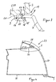
- eine perspektivische Vorderansicht einer Leuchteinheit,
- Figur 2
- einen Vertikalschnitt durch die Leuchteinheit gemäß Figur 1 in einem Bereich, in dem eine Abdeckscheibe mit einem sich nach unten anschließenden Anschlussteil verbunden ist,
- Figur 3
- eine vergrößerte Darstellung eines Verbindungsbereiches X in Figur 2 zwischen der Abdeckscheibe und dem Anschlussteil,
- Figur 4
- einen Vertikalschnitt durch eine Leuchteinheit gemäß Figur 1 in einem Bereich, in dem eine Abdeckscheibe mit einem sich nach oben anschließenden Anschlussteil verbunden ist, und
- Figur 5
- eine vergrößerte Darstellung eines Verbindungsbereiches Y in Figur 4 zwischen der Abdeckscheibe und dem angrenzenden Anschlussteil.
- Eine Leuchteinheit 1 für Fahrzeuge, die vorzugsweise als ein Scheinwerfer ausgebildet ist, weist ein Leuchtengehäuse 2 auf, in dem lichttechnische Komponenten, wie beispielsweise eine nicht dargestellte Lichtquelle und ein nicht dargestellter Reflektor, angeordnet sind. Eine Lichtaustrittsöffnung des Leuchtengehäuses 2 ist durch eine glasklare Abdeckscheibe 3 abgeschlossen.
- Zur Verbindung der Abdeckscheibe 3 mit dem Leuchtengehäuse 2 ist ein freies Ende 4 eines Randes 5 der Abdeckscheibe 3 entlang eines Teilumfangs derselben in einer Nut 6 des Leuchtengehäuses 2 in herkömmlicher Form befestigt. Dabei kann der Rand 5 über eine elastische Dichtung (Verbindung) in der Nut 6 gelagert sein, so dass eine Kompensation von Bauteil- bzw. Fügetoleranzen gewährleistet ist.
- Nach der Erfindung erfolgt die Verbindung zwischen der Abdeckscheibe 3 und sich an dieselbe anschließenden Anschlussteilen 7 über direkt an dem Rand 5 der Abdeckscheibe 3 angeordnete Befestigungsmittel.
- Nach einer ersten Ausführungsform der Leuchteinheit 1 gemäß den Figuren 2 und 3 ist als Anschlussteil 7 eine Stoßfängerabdeckung (Karosserieteil) mit einem Randelement 8 desselben in einer Aufnahmenut 9 des Randes 5 der Abdeckscheibe 3 gelagert. Dieser lösbare Befestigungsbereich X zwischen der Abdeckscheibe 3 und der Stoßfängerabdeckung 7 ist in einem fahrzeugaußenhautnahen Bereich angeordnet.
- Zur Befestigung der Abdeckscheibe 3 an dem Leuchtengehäuse 2 erstreckt sich der Rand 5 der Abdeckscheibe 3 im wesentlichen geradlinig entgegen der Lichtaustrittsrichtung zu der Nutaufnahme 6 des Leuchtengehäuses 2 hingerichtet. Die Befestigung der Abdeckscheibe 3 mit dem Leuchtengehäuse 2 ist in einem fahrzeugaußenhautfernen Bereich angeordnet.
- Wie aus Figur 2 zu ersehen ist, erstreckt sich die Aufnahmenut 9 der Abdeckscheibe 3 lediglich in einem unteren Bereich 10 der Abdeckscheibe 3. In einem oberen Bereich 11 der Abdeckscheibe 3 ist keine Nut vorgesehen, so dass ein benachbartes Anschlussteil 12 (Karosserieteil) mit einem freien Randelement 13 unmittelbar an einem abgewinkelten oberen Randabschnitt 14 der Abdeckscheibe 3 anliegt. Das obere Anschlussteil 12 ist als Motorhaube ausgebildet, so dass eine Verbindung mit der Abdeckscheibe 3 nicht erwünscht ist.
- Wie besser aus Figur 3 zu ersehen ist, weist ein dem Anschlussteil 7 zugewandter und seitlich von dem Rand 5 abragender erster Schenkel 15 der Nut 9 einen Hinterschnitt 16 auf, so dass ein verbreitertes Ende 17 des Randelementes 8 rastend in die Nut 9 eingreifen kann. Sowohl der erste Schenkel 15 der Nut 9 als auch das verbreiterte Ende 17 des Randelementes 8 weisen eine abgeschrägte Rastfläche 18 bzw. 18' auf, so dass das untere Anschlussteil 7 auf einfache Weise rastend montiert werden kann und in dieser Raststellung selbsthaltend verbunden ist.
- Die Nut 9 der Abdeckscheibe 3 weist eine solche Breite B auf, dass zum einen das Randelement 8 des Anschlussteils 7 lagesicher gehalten ist und zum anderen eine annähernd spaltfreie Fuge 19 zwischen der Abdeckscheibe 3 und dem Anschlussteil 7 gebildet wird. Vorteilhaft kann hierdurch eine definierte Fugenbildung vorgegebener Breite erzielt werden.
- Nach einer nicht dargestellten Ausführungsform der Erfindung kann der erste Schenkel 15 auch eine konstante Breite aufweisen (ohne Hinterschnitt), so dass das Randelement 8 des Anschlussteils 7 ohne Vorspannung in derselben gelagert ist. Gegebenenfalls kann in einem Scheitelbereich 20 der Nut 9 eine Dichtung vorgesehen sein. Dadurch, dass das Randelement 8 des Anschlussteils 7 ohne Haltewirkung in der Nut 9 der Abdeckscheibe 3 eingesetzt ist, sind vorzugsweise an anderer Stelle Klammerelemente vorgesehen, die eine definierte klemmende Verbindung zwischen der Abdeckscheibe 3 und dem Leuchtengehäuse 2 bewirken. Das Klammerelement kann beispielsweise eine zusätzliche Nase am Fuße des Schenkels der Abdeckscheibe 3 und einen Schenkel des Leuchtengehäuses 2 umgreifen. Hierbei dient die Nut 9 der Abdeckscheibe 3 lediglich zur Aufnahme des Randelementes 8 des Anschlussteiles 3, ohne dass den Teilen in diesem Verbindungsbereich eine Hefestigungsfunktion zukommt.
- Nach einer weiteren Ausführungsform der Erfindung gemäß der Figuren 4 und 5 ist die Leuchteinheit 1 mit einem Leuchtengehäuse 26 und einer Abdeckscheibe 27 versehen, wobei die Abdeckscheibe 27 eine Nut 28 lediglich in einem oberen Bereich 29 der Abdeckscheibe 27 aufweist. Wie im vorhergehenden Ausführungsbeispiel ragt seitlich von einem Rand 30 der Abdeckscheibe 27 ein Schenkel 31 der Nut 28 derart ab, dass eine in Lichtaustrittsrichtung geöffnete Nut 28 gebildet wird. Der Schenkel 31 sowie ein Randelement 32 eines sich nach oben hin an die Abdeckscheibe 27 anschließenden Anschlussteils 33 bilden die Befestigungsmittel, die in gleicher Weise wie bei dem vorhergehenden Ausführungsbeispiel zu einer lösbaren Rastverbindung zwischen der Abdeckscheibe 27 und dem Anschlussteil 33 führen. Die übereinstimmenden Bau-/Funktionsteile der Befestigungsmittel sind daher mit den gleichen Bezugsziffern versehen.
- Das Randelement 32 erstreckt sich hakenförmig entgegen der Lichtaustrittsrichtung, wobei es mit einem auf der dem Schenkel 31 abgewandten Seite erstreckenden Flächenabschnitt 34 unmittelbar auf einer Außenfläche 35 des Randes 30 der Abdeckscheibe 27 zur Anlage kommt. Diese flächige Anlage wird durch die klemmende Kraft des Schenkels 31 bewirkt, dessen endseitiger lichter Abstand zu der Außenfläche 35 im Ausgangszustand geringer ist als die Dicke des Randelementes 32 am Fuß der Rastfläche 18'.
- Die Tiefe der Nut 28 bzw. die Länge des Randelementes 32 ist derart aufeinander abgestimmt, dass sich das Anschlussteil 33 quasi spaltfrei und bündig zu einer von außen sichtbaren Abdeckfläche 36 der Abdeckscheibe 27 erstreckt. Die Orientierung und Formgebung der Nut 28 bzw. des Randelementes 32 ist an die gewünschte Kontur der Abdeckscheibe 27 und des sich anschließenden Anschlussteils 33 angepasst. Im vorliegenden Ausführungsbeispiel können das Anschlussteil 33 und die Abdeckscheibe 27 bogenförmig ineinander übergehen. Es entsteht somit ein optisch homogener und einheitlicher Eindruck der zueinander benachbarten Bauteile 27, 33.
- Alternativ kann das Anschlussteil 7, 33 auch eine Aufnahme (Nut) aufweisen, in die ein Randelement der Abdeckscheibe 3, 27 eingreift.
Claims (10)
- Leuchteinheit für Fahrzeuge mit einem Leuchtengehäuse, in dem lichttechnische Komponenten angeordnet sind, und mit einer eine Lichtaustrittsöffnung des Leuchtengehäuses abschließenden Abdeckscheibe, wobei ein Rand der Abdeckscheibe in einer Nut des Leuchtengehäuses befestigt ist, dadurch gekennzeichnet, dass die Abdeckscheibe (3, 27) in einem Randbereich (10, 29) derselben eine Aufnahme (9, 28) für ein Randelement (8, 32) eines Anschlussteils (7, 33) aufweist.
- Leuchteinheit nach Anspruch 1, dadurch gekennzeichnet, dass die Aufnahme der Abdeckscheibe (3, 27) als eine Nut (9, 28) ausgebildet ist, die umlaufend oder teilweise umlaufend verläuft und eine solche Breite (B) aufweist, dass das Randelement (8, 32) des Anschlussteils (7, 33) lagesicher gehalten ist.
- Leuchteinheit nach Anspruch 1 oder 2, dadurch gekennzeichnet, dass das Randelement (8, 32) des Anschlussteils (7, 33) teilweise oder vollständig entlang einer durch die Abdeckscheibe (3, 27) und durch das benachbarte Anschlussteil (7, 33) gebildeten gemeinsamen Fugenlinie (19) erstreckt.
- Leuchteinheit nach einem der Ansprüche 1 bis 3, dadurch gekennzeichnet, dass die Nut (9, 28) der Abdeckscheibe (3, 27) und das Randelement (8, 32) des Anschlussteils (7, 33) rastend und/oder selbsthaltend miteinander verbunden sind.
- Leuchteinheit nach einem der Ansprüche 1 bis 4, dadurch gekennzeichnet, dass die Nut (9, 28) der Abdeckscheibe (3, 27) und/oder das Randelement (8, 32) des Anschlussteils (7, 33) derart ausgebildet sind, dass das Randelement (8, 32) nach dem Einstecken in die Nut (9, 28) eine vorgegebene Montageposition einnimmt.
- Leuchteinheit nach einem der Ansprüche 1 bis 5, dadurch gekennzeichnet, dass die Nut (9, 28) der Abdeckscheibe (3, 27) einen seitlich abragenden Schenkel (15, 31) mit einem Hinterschnitt (16) aufweist, derart, dass das Randelement (8, 32) des Anschlussteils (7, 33) im wesentlichen durch Verklipsung in der Nut (9, 28) der Abdeckscheibe (3, 27) gehalten ist.
- Leuchteinheit nach einem der Ansprüche 1 bis 6, dadurch gekennzeichnet, dass die Tiefe und/oder die Kontur der Nut (9, 28) der Abdeckscheibe (3, 27) und/oder die Kontur des Wandelementes (8, 32) des Anschlussteils (7, 33) derart ausgebildet sind, dass sich die unmittelbar an der Nut (9, 28) und dem Randelement (8, 32) anschließende Abdeckfläche (36) der Abdeckscheibe (3, 27) bzw. ein Flächenabschnitt des Anschlussteils (7, 33) bündig zueinander erstrecken.
- Leuchteinheit nach einem der Ansprüche 1 bis 7, dadurch gekennzeichnet, dass in einem Scheitelbereich (20) der Nut (9, 28) eine Dichtung angeordnet ist.
- Leuchteinheit nach einem der Ansprüche 1 bis 8, dadurch gekennzeichnet, dass der Rand (5) der Abdeckscheibe (3) über eine elastische Dichtung in der Nut (6) des Leuchtengehäuses (2) gelagert ist.
- Leuchteinheit nach einem der Ansprüche 1 bis 9, dadurch gekennzeichnet, dass die Abdeckscheibe (3, 27) und/oder das Leuchtengehäuse (2) in einem zueinandergekehrten Randbereich derart ausgebildet sind, dass ein zusätzliches Klammerelement angreifbar ist zur lösbaren Verbindung der Abdeckscheibe (3) mit dem Leuchtengehäuse (2).
Applications Claiming Priority (2)
| Application Number | Priority Date | Filing Date | Title |
|---|---|---|---|
| DE10352834 | 2003-11-10 | ||
| DE10352834A DE10352834A1 (de) | 2003-11-10 | 2003-11-10 | Leuchteinheit für Fahrzeuge |
Publications (2)
| Publication Number | Publication Date |
|---|---|
| EP1529686A1 EP1529686A1 (de) | 2005-05-11 |
| EP1529686B1 true EP1529686B1 (de) | 2006-01-25 |
Family
ID=34428693
Family Applications (1)
| Application Number | Title | Priority Date | Filing Date |
|---|---|---|---|
| EP04019478A Expired - Lifetime EP1529686B1 (de) | 2003-11-10 | 2004-08-17 | Leuchteinheit für Fahrzeuge |
Country Status (2)
| Country | Link |
|---|---|
| EP (1) | EP1529686B1 (de) |
| DE (2) | DE10352834A1 (de) |
Cited By (1)
| Publication number | Priority date | Publication date | Assignee | Title |
|---|---|---|---|---|
| FR3143720A1 (fr) * | 2022-12-19 | 2024-06-21 | Psa Automobiles Sa | Dispositif d’éclairage pour face avant de véhicule automobile. |
Families Citing this family (13)
| Publication number | Priority date | Publication date | Assignee | Title |
|---|---|---|---|---|
| DE102005012104A1 (de) * | 2005-03-10 | 2006-09-14 | Schefenacker Vision Systems Germany Gmbh | Gehäuse, insbesondere Spiegelgehäuse |
| FR2903646B1 (fr) * | 2006-07-13 | 2009-04-17 | Peugeot Citroen Automobiles Sa | Dispositif de positionnement d'elements de carrosserie d'une face avant d'un vehicule automobile et vehicule automobile comportant une telle face avant. |
| FR2904598B1 (fr) * | 2006-08-01 | 2008-11-07 | Peugeot Citroen Automobiles Sa | Dispositif de montage d'un feu de signalisation et d'une peau de pare-chocs sur une structure arriere d'un vehicule automobile et vehicule comportant au moins un tel dispositif |
| FR2909333B1 (fr) * | 2006-12-05 | 2009-07-24 | Renault Sas | Agencement de moyens de support d'un bouclier de vehicule automobile |
| DE102007006218B4 (de) * | 2007-02-08 | 2017-07-20 | Volkswagen Ag | Befestigungsanordnung für eine Leuchte an einem Fahrzeug |
| DE102007010211B4 (de) | 2007-03-02 | 2022-04-28 | HELLA GmbH & Co. KGaA | Leuchteinheit für Fahrzeuge und Montageverfahren |
| FR2914265B1 (fr) * | 2007-03-28 | 2009-09-18 | Peugeot Citroen Automobiles Sa | Dispositif de positionnement d'une peau de pare-chocs d'une face avant de vehicule automobile |
| DE102009006439A1 (de) | 2009-01-28 | 2010-07-29 | Volkswagen Ag | Scheinwerferbefestigung an einem Fahrzeug |
| DE102012022281A1 (de) | 2012-11-14 | 2014-05-15 | Volkswagen Ag | Leuchteinheit für Fahrzeuge und Verfahren zur Montage einer lichtdurchlässigen Abdeckscheibe an einem Leuchtengehäuse einer Leuchteinheit eines Fahrzeugs |
| FR3035855B1 (fr) * | 2015-05-06 | 2018-11-16 | Renault S.A.S. | Vehicule comprenant un bouclier fixe a un projecteur |
| FR3051412B1 (fr) * | 2016-05-23 | 2019-04-26 | Peugeot Citroen Automobiles Sa | Dispositif d’eclairage et/ou de signalisation pour vehicule automobile destine a etre implante dans un element de carrosserie |
| FR3120576A1 (fr) * | 2021-03-15 | 2022-09-16 | Psa Automobiles Sa | Véhicule terrestre à pare-chocs s’appuyant sur des blocs optiques |
| CN116394873A (zh) * | 2023-04-13 | 2023-07-07 | 东风彼欧汽车外饰系统有限公司 | 一种带贯穿灯式防自重下沉前保险杠 |
Family Cites Families (7)
| Publication number | Priority date | Publication date | Assignee | Title |
|---|---|---|---|---|
| FR2432136A1 (fr) * | 1978-07-24 | 1980-02-22 | Seima | Projecteur, notamment pour vehicule automobile |
| JPS6088645A (ja) * | 1983-10-19 | 1985-05-18 | Nissan Motor Co Ltd | 自動車用灯具の取付部構造 |
| DE3402274A1 (de) * | 1984-01-24 | 1985-08-01 | Bosch Gmbh Robert | Scheinwerfer fuer fahrzeuge, insbesondere fuer kraftfahrzeuge |
| DE19615026A1 (de) * | 1995-04-27 | 1996-10-31 | Volkswagen Ag | Befestigungsvorrichtung für einen Scheinwerfer eines Kraftfahrzeuges |
| FR2749237B1 (fr) * | 1996-06-04 | 1998-08-21 | Valeo Vision | Dispositif d'eclairage ou de signalisation a joint surmoule pour vehicule |
| US6190030B1 (en) * | 1999-02-18 | 2001-02-20 | Lacks Industries, Inc. | Flexible lamp mounting |
| DE10211972A1 (de) * | 2002-03-19 | 2003-10-16 | Bayerische Motoren Werke Ag | Leuchteneinheit für ein Fahrzeug |
-
2003
- 2003-11-10 DE DE10352834A patent/DE10352834A1/de not_active Withdrawn
-
2004
- 2004-08-17 EP EP04019478A patent/EP1529686B1/de not_active Expired - Lifetime
- 2004-08-17 DE DE502004000262T patent/DE502004000262D1/de not_active Expired - Lifetime
Cited By (1)
| Publication number | Priority date | Publication date | Assignee | Title |
|---|---|---|---|---|
| FR3143720A1 (fr) * | 2022-12-19 | 2024-06-21 | Psa Automobiles Sa | Dispositif d’éclairage pour face avant de véhicule automobile. |
Also Published As
| Publication number | Publication date |
|---|---|
| EP1529686A1 (de) | 2005-05-11 |
| DE502004000262D1 (de) | 2006-04-13 |
| DE10352834A1 (de) | 2005-06-09 |
Similar Documents
| Publication | Publication Date | Title |
|---|---|---|
| EP1529686B1 (de) | Leuchteinheit für Fahrzeuge | |
| DE3333474A1 (de) | Kanalfoermiger dicht-/abschlussstreifen | |
| DE20321549U1 (de) | Dicht-, Trimm- oder Führungsleiste | |
| DE202010013082U1 (de) | Scheibeneinheit und deren Herstellung | |
| DE10060447B4 (de) | Innenspiegelanordnung | |
| WO2019149741A1 (de) | Dachantenne eines fahrzeuges mit einer rückfahrkamera | |
| DE19718509C1 (de) | Vorrichtung zur schraubenlosen Montage eines Ausstattungsteils | |
| DE102011106951A1 (de) | Kraftfahrzeugkarosserie | |
| DE69627022T2 (de) | Ein Element zur Verbindung an einer Dachrinne oder Ähnlichem und ein Verfahren zur Herstellung eines solchen Elements | |
| DE102004037185B4 (de) | Verbindungsclip für ein Zierelement eines Kraftfahrzeugs | |
| EP1538022A2 (de) | Leuchteinheit für Fahrzeuge | |
| DE10046358B4 (de) | Kederanordnung zum Halten einer Türscheibe eines Kraftfahrzeugs | |
| DE102008011718B4 (de) | Scheinwerfer für ein Kraftfahrzeug mit einer Einstelleinrichtung | |
| EP0904980B1 (de) | Befestigungssystem für eine Blinkleuchte | |
| EP1516781B1 (de) | Scheinwerfer für Fahrzeuge | |
| DE19530347B4 (de) | Anordnung zur Befestigung eines Anbauteils an einem Grundkörper | |
| EP0838369B1 (de) | Kombination einer Leuchte oder eines Scheinwerfers und eines Fahrzeugteils | |
| EP1504955B1 (de) | Vorrichtung zur Positionierung zweier Verkleidungsteile, insbesondere eines Scheinwerfers und eines Stossfängers, an einer Kraftfahrzeugkarosserie | |
| DE3636176C2 (de) | ||
| EP1000804B1 (de) | Scheinwerfer für Fahrzeuge | |
| DE10335878B4 (de) | Befestigungsvorrichtung für eine Leuchtenanordnung | |
| DE10234459B4 (de) | Verbindungselement zum Befestigen eines optischen Leuchtenbauteils an einer Leuchte und Leuchte | |
| EP1650492B1 (de) | Scheinwerfer für Fahrzeuge und Herstellungsverfahren | |
| DE29906009U1 (de) | Feuchtraumleuchte | |
| DE102016107858B4 (de) | Heckblendenanordnung eines Kraftfahrzeugs |
Legal Events
| Date | Code | Title | Description |
|---|---|---|---|
| PUAI | Public reference made under article 153(3) epc to a published international application that has entered the european phase |
Free format text: ORIGINAL CODE: 0009012 |
|
| AK | Designated contracting states |
Kind code of ref document: A1 Designated state(s): AT BE BG CH CY CZ DE DK EE ES FI FR GB GR HU IE IT LI LU MC NL PL PT RO SE SI SK TR |
|
| AX | Request for extension of the european patent |
Extension state: AL HR LT LV MK |
|
| GRAP | Despatch of communication of intention to grant a patent |
Free format text: ORIGINAL CODE: EPIDOSNIGR1 |
|
| 17P | Request for examination filed |
Effective date: 20050428 |
|
| GRAS | Grant fee paid |
Free format text: ORIGINAL CODE: EPIDOSNIGR3 |
|
| GRAA | (expected) grant |
Free format text: ORIGINAL CODE: 0009210 |
|
| AK | Designated contracting states |
Kind code of ref document: B1 Designated state(s): DE FR GB IT |
|
| REG | Reference to a national code |
Ref country code: GB Ref legal event code: FG4D Free format text: NOT ENGLISH |
|
| AKX | Designation fees paid |
Designated state(s): DE FR GB IT |
|
| GBT | Gb: translation of ep patent filed (gb section 77(6)(a)/1977) |
Effective date: 20060307 |
|
| REF | Corresponds to: |
Ref document number: 502004000262 Country of ref document: DE Date of ref document: 20060413 Kind code of ref document: P |
|
| RAP2 | Party data changed (patent owner data changed or rights of a patent transferred) |
Owner name: HBPO GMBH Owner name: BMW AG Owner name: HELLA KGAA HUECK & CO. |
|
| ET | Fr: translation filed | ||
| PLBE | No opposition filed within time limit |
Free format text: ORIGINAL CODE: 0009261 |
|
| STAA | Information on the status of an ep patent application or granted ep patent |
Free format text: STATUS: NO OPPOSITION FILED WITHIN TIME LIMIT |
|
| 26N | No opposition filed |
Effective date: 20061026 |
|
| REG | Reference to a national code |
Ref country code: DE Ref legal event code: R082 Ref document number: 502004000262 Country of ref document: DE Representative=s name: PATENTANWAELTE FIEDLER, OSTERMANN & SCHNEIDER, DE Ref country code: DE Ref legal event code: R081 Ref document number: 502004000262 Country of ref document: DE Owner name: HELLA KGAA HUECK & CO., DE Free format text: FORMER OWNER: HELLA KGAA HUECK & CO., HBPO GMBH, BAYERISCHE MOTOREN WERKE AKTIEN, , DE Ref country code: DE Ref legal event code: R081 Ref document number: 502004000262 Country of ref document: DE Owner name: HBPO GMBH, DE Free format text: FORMER OWNER: HELLA KGAA HUECK & CO., HBPO GMBH, BAYERISCHE MOTOREN WERKE AKTIEN, , DE Ref country code: DE Ref legal event code: R081 Ref document number: 502004000262 Country of ref document: DE Owner name: HELLA KGAA HUECK & CO., DE Free format text: FORMER OWNERS: HELLA KGAA HUECK & CO., 59557 LIPPSTADT, DE; HBPO GMBH, 59557 LIPPSTADT, DE; BAYERISCHE MOTOREN WERKE AKTIENGESELLSCHAFT, 80809 MUENCHEN, DE Ref country code: DE Ref legal event code: R081 Ref document number: 502004000262 Country of ref document: DE Owner name: HBPO GMBH, DE Free format text: FORMER OWNERS: HELLA KGAA HUECK & CO., 59557 LIPPSTADT, DE; HBPO GMBH, 59557 LIPPSTADT, DE; BAYERISCHE MOTOREN WERKE AKTIENGESELLSCHAFT, 80809 MUENCHEN, DE Ref country code: DE Ref legal event code: R081 Ref document number: 502004000262 Country of ref document: DE Owner name: HELLA GMBH & CO. KGAA, DE Free format text: FORMER OWNERS: HELLA KGAA HUECK & CO., 59557 LIPPSTADT, DE; HBPO GMBH, 59557 LIPPSTADT, DE; BAYERISCHE MOTOREN WERKE AKTIENGESELLSCHAFT, 80809 MUENCHEN, DE |
|
| REG | Reference to a national code |
Ref country code: FR Ref legal event code: PLFP Year of fee payment: 13 |
|
| PGFP | Annual fee paid to national office [announced via postgrant information from national office to epo] |
Ref country code: DE Payment date: 20160811 Year of fee payment: 13 |
|
| REG | Reference to a national code |
Ref country code: FR Ref legal event code: PLFP Year of fee payment: 14 |
|
| PGFP | Annual fee paid to national office [announced via postgrant information from national office to epo] |
Ref country code: IT Payment date: 20170824 Year of fee payment: 14 Ref country code: GB Payment date: 20170824 Year of fee payment: 14 |
|
| REG | Reference to a national code |
Ref country code: DE Ref legal event code: R082 Ref document number: 502004000262 Country of ref document: DE Representative=s name: PATENTANWAELTE FIEDLER, OSTERMANN & SCHNEIDER, DE Ref country code: DE Ref legal event code: R081 Ref document number: 502004000262 Country of ref document: DE Owner name: HELLA GMBH & CO. KGAA, DE Free format text: FORMER OWNERS: HBPO GMBH, 59557 LIPPSTADT, DE; HELLA KGAA HUECK & CO., 59557 LIPPSTADT, DE Ref country code: DE Ref legal event code: R081 Ref document number: 502004000262 Country of ref document: DE Owner name: HBPO GMBH, DE Free format text: FORMER OWNERS: HBPO GMBH, 59557 LIPPSTADT, DE; HELLA KGAA HUECK & CO., 59557 LIPPSTADT, DE |
|
| REG | Reference to a national code |
Ref country code: DE Ref legal event code: R119 Ref document number: 502004000262 Country of ref document: DE |
|
| PG25 | Lapsed in a contracting state [announced via postgrant information from national office to epo] |
Ref country code: DE Free format text: LAPSE BECAUSE OF NON-PAYMENT OF DUE FEES Effective date: 20180301 |
|
| REG | Reference to a national code |
Ref country code: FR Ref legal event code: PLFP Year of fee payment: 15 |
|
| GBPC | Gb: european patent ceased through non-payment of renewal fee |
Effective date: 20180817 |
|
| PG25 | Lapsed in a contracting state [announced via postgrant information from national office to epo] |
Ref country code: IT Free format text: LAPSE BECAUSE OF NON-PAYMENT OF DUE FEES Effective date: 20180817 |
|
| REG | Reference to a national code |
Ref country code: FR Ref legal event code: PLFP Year of fee payment: 16 |
|
| PG25 | Lapsed in a contracting state [announced via postgrant information from national office to epo] |
Ref country code: GB Free format text: LAPSE BECAUSE OF NON-PAYMENT OF DUE FEES Effective date: 20180817 |
|
| PGFP | Annual fee paid to national office [announced via postgrant information from national office to epo] |
Ref country code: FR Payment date: 20190822 Year of fee payment: 16 |
|
| PG25 | Lapsed in a contracting state [announced via postgrant information from national office to epo] |
Ref country code: FR Free format text: LAPSE BECAUSE OF NON-PAYMENT OF DUE FEES Effective date: 20200831 |