EP1529875A2 - Waschmaschine und dazugehöriges Regelungsverfahren - Google Patents
Waschmaschine und dazugehöriges Regelungsverfahren Download PDFInfo
- Publication number
- EP1529875A2 EP1529875A2 EP04256776A EP04256776A EP1529875A2 EP 1529875 A2 EP1529875 A2 EP 1529875A2 EP 04256776 A EP04256776 A EP 04256776A EP 04256776 A EP04256776 A EP 04256776A EP 1529875 A2 EP1529875 A2 EP 1529875A2
- Authority
- EP
- European Patent Office
- Prior art keywords
- water
- drum
- steam
- washing apparatus
- detergent
- Prior art date
- Legal status (The legal status is an assumption and is not a legal conclusion. Google has not performed a legal analysis and makes no representation as to the accuracy of the status listed.)
- Withdrawn
Links
Images













Classifications
-
- D—TEXTILES; PAPER
- D06—TREATMENT OF TEXTILES OR THE LIKE; LAUNDERING; FLEXIBLE MATERIALS NOT OTHERWISE PROVIDED FOR
- D06F—LAUNDERING, DRYING, IRONING, PRESSING OR FOLDING TEXTILE ARTICLES
- D06F25/00—Washing machines with receptacles, e.g. perforated, having a rotary movement, e.g. oscillatory movement, the receptacle serving both for washing and for centrifugally separating water from the laundry and having further drying means, e.g. using hot air
-
- D—TEXTILES; PAPER
- D06—TREATMENT OF TEXTILES OR THE LIKE; LAUNDERING; FLEXIBLE MATERIALS NOT OTHERWISE PROVIDED FOR
- D06F—LAUNDERING, DRYING, IRONING, PRESSING OR FOLDING TEXTILE ARTICLES
- D06F33/00—Control of operations performed in washing machines or washer-dryers
- D06F33/50—Control of washer-dryers characterised by the purpose or target of the control
- D06F33/52—Control of the operational steps, e.g. optimisation or improvement of operational steps depending on the condition of the laundry
- D06F33/54—Control of the operational steps, e.g. optimisation or improvement of operational steps depending on the condition of the laundry of water filling
-
- D—TEXTILES; PAPER
- D06—TREATMENT OF TEXTILES OR THE LIKE; LAUNDERING; FLEXIBLE MATERIALS NOT OTHERWISE PROVIDED FOR
- D06F—LAUNDERING, DRYING, IRONING, PRESSING OR FOLDING TEXTILE ARTICLES
- D06F39/00—Details of washing machines not specific to a single type of machines covered by groups D06F9/00 - D06F27/00
- D06F39/40—Steam generating arrangements
-
- D—TEXTILES; PAPER
- D06—TREATMENT OF TEXTILES OR THE LIKE; LAUNDERING; FLEXIBLE MATERIALS NOT OTHERWISE PROVIDED FOR
- D06F—LAUNDERING, DRYING, IRONING, PRESSING OR FOLDING TEXTILE ARTICLES
- D06F43/00—Dry-cleaning apparatus or methods using volatile solvents
-
- D—TEXTILES; PAPER
- D06—TREATMENT OF TEXTILES OR THE LIKE; LAUNDERING; FLEXIBLE MATERIALS NOT OTHERWISE PROVIDED FOR
- D06F—LAUNDERING, DRYING, IRONING, PRESSING OR FOLDING TEXTILE ARTICLES
- D06F43/00—Dry-cleaning apparatus or methods using volatile solvents
- D06F43/007—Dry cleaning methods
-
- D—TEXTILES; PAPER
- D06—TREATMENT OF TEXTILES OR THE LIKE; LAUNDERING; FLEXIBLE MATERIALS NOT OTHERWISE PROVIDED FOR
- D06F—LAUNDERING, DRYING, IRONING, PRESSING OR FOLDING TEXTILE ARTICLES
- D06F43/00—Dry-cleaning apparatus or methods using volatile solvents
- D06F43/02—Dry-cleaning apparatus or methods using volatile solvents having one rotary cleaning receptacle only
-
- D—TEXTILES; PAPER
- D06—TREATMENT OF TEXTILES OR THE LIKE; LAUNDERING; FLEXIBLE MATERIALS NOT OTHERWISE PROVIDED FOR
- D06F—LAUNDERING, DRYING, IRONING, PRESSING OR FOLDING TEXTILE ARTICLES
- D06F58/00—Domestic laundry dryers
- D06F58/20—General details of domestic laundry dryers
- D06F58/203—Laundry conditioning arrangements
-
- D—TEXTILES; PAPER
- D06—TREATMENT OF TEXTILES OR THE LIKE; LAUNDERING; FLEXIBLE MATERIALS NOT OTHERWISE PROVIDED FOR
- D06F—LAUNDERING, DRYING, IRONING, PRESSING OR FOLDING TEXTILE ARTICLES
- D06F2103/00—Parameters monitored or detected for the control of domestic laundry washing machines, washer-dryers or laundry dryers
- D06F2103/16—Washing liquid temperature
-
- D—TEXTILES; PAPER
- D06—TREATMENT OF TEXTILES OR THE LIKE; LAUNDERING; FLEXIBLE MATERIALS NOT OTHERWISE PROVIDED FOR
- D06F—LAUNDERING, DRYING, IRONING, PRESSING OR FOLDING TEXTILE ARTICLES
- D06F2103/00—Parameters monitored or detected for the control of domestic laundry washing machines, washer-dryers or laundry dryers
- D06F2103/18—Washing liquid level
-
- D—TEXTILES; PAPER
- D06—TREATMENT OF TEXTILES OR THE LIKE; LAUNDERING; FLEXIBLE MATERIALS NOT OTHERWISE PROVIDED FOR
- D06F—LAUNDERING, DRYING, IRONING, PRESSING OR FOLDING TEXTILE ARTICLES
- D06F2103/00—Parameters monitored or detected for the control of domestic laundry washing machines, washer-dryers or laundry dryers
- D06F2103/28—Air properties
- D06F2103/34—Humidity
-
- D—TEXTILES; PAPER
- D06—TREATMENT OF TEXTILES OR THE LIKE; LAUNDERING; FLEXIBLE MATERIALS NOT OTHERWISE PROVIDED FOR
- D06F—LAUNDERING, DRYING, IRONING, PRESSING OR FOLDING TEXTILE ARTICLES
- D06F2105/00—Systems or parameters controlled or affected by the control systems of washing machines, washer-dryers or laundry dryers
- D06F2105/02—Water supply
-
- D—TEXTILES; PAPER
- D06—TREATMENT OF TEXTILES OR THE LIKE; LAUNDERING; FLEXIBLE MATERIALS NOT OTHERWISE PROVIDED FOR
- D06F—LAUNDERING, DRYING, IRONING, PRESSING OR FOLDING TEXTILE ARTICLES
- D06F2105/00—Systems or parameters controlled or affected by the control systems of washing machines, washer-dryers or laundry dryers
- D06F2105/28—Electric heating
-
- D—TEXTILES; PAPER
- D06—TREATMENT OF TEXTILES OR THE LIKE; LAUNDERING; FLEXIBLE MATERIALS NOT OTHERWISE PROVIDED FOR
- D06F—LAUNDERING, DRYING, IRONING, PRESSING OR FOLDING TEXTILE ARTICLES
- D06F33/00—Control of operations performed in washing machines or washer-dryers
- D06F33/50—Control of washer-dryers characterised by the purpose or target of the control
- D06F33/72—Control of the energy or water consumption
-
- D—TEXTILES; PAPER
- D06—TREATMENT OF TEXTILES OR THE LIKE; LAUNDERING; FLEXIBLE MATERIALS NOT OTHERWISE PROVIDED FOR
- D06F—LAUNDERING, DRYING, IRONING, PRESSING OR FOLDING TEXTILE ARTICLES
- D06F34/00—Details of control systems for washing machines, washer-dryers or laundry dryers
- D06F34/08—Control circuits or arrangements thereof
-
- D—TEXTILES; PAPER
- D06—TREATMENT OF TEXTILES OR THE LIKE; LAUNDERING; FLEXIBLE MATERIALS NOT OTHERWISE PROVIDED FOR
- D06F—LAUNDERING, DRYING, IRONING, PRESSING OR FOLDING TEXTILE ARTICLES
- D06F39/00—Details of washing machines not specific to a single type of machines covered by groups D06F9/00 - D06F27/00
- D06F39/04—Heating arrangements
-
- D—TEXTILES; PAPER
- D06—TREATMENT OF TEXTILES OR THE LIKE; LAUNDERING; FLEXIBLE MATERIALS NOT OTHERWISE PROVIDED FOR
- D06F—LAUNDERING, DRYING, IRONING, PRESSING OR FOLDING TEXTILE ARTICLES
- D06F39/00—Details of washing machines not specific to a single type of machines covered by groups D06F9/00 - D06F27/00
- D06F39/08—Liquid supply or discharge arrangements
- D06F39/087—Water level measuring or regulating devices
-
- D—TEXTILES; PAPER
- D06—TREATMENT OF TEXTILES OR THE LIKE; LAUNDERING; FLEXIBLE MATERIALS NOT OTHERWISE PROVIDED FOR
- D06F—LAUNDERING, DRYING, IRONING, PRESSING OR FOLDING TEXTILE ARTICLES
- D06F39/00—Details of washing machines not specific to a single type of machines covered by groups D06F9/00 - D06F27/00
- D06F39/08—Liquid supply or discharge arrangements
- D06F39/088—Liquid supply arrangements
-
- D—TEXTILES; PAPER
- D06—TREATMENT OF TEXTILES OR THE LIKE; LAUNDERING; FLEXIBLE MATERIALS NOT OTHERWISE PROVIDED FOR
- D06F—LAUNDERING, DRYING, IRONING, PRESSING OR FOLDING TEXTILE ARTICLES
- D06F58/00—Domestic laundry dryers
- D06F58/02—Domestic laundry dryers having dryer drums rotating about a horizontal axis
- D06F58/04—Details
-
- D—TEXTILES; PAPER
- D06—TREATMENT OF TEXTILES OR THE LIKE; LAUNDERING; FLEXIBLE MATERIALS NOT OTHERWISE PROVIDED FOR
- D06F—LAUNDERING, DRYING, IRONING, PRESSING OR FOLDING TEXTILE ARTICLES
- D06F58/00—Domestic laundry dryers
- D06F58/20—General details of domestic laundry dryers
- D06F58/26—Heating arrangements, e.g. gas heating equipment
Definitions
- the present invention relates to a washing apparatus, and more particularly, to a washing apparatus and control method thereof, by which laundry can be dry-cleaned.
- washing apparatuses include a washing machine, a laundry dryer, and a washer/dryer.
- the washing machine is for performing washing on various kinds of laundries.
- the laundry dryer is performing drying on a washing-completed wet laundry, and, the washer/dryer is for performing both washing and drying.
- the washing apparatuses such as the washing machine, laundry dryer, washer/dryer, and the like carries out only the general washing and/or drying on the laundry.
- a general washing apparatus as a home appliance is unable to perform dry cleaning.
- the dry-cleaning kit is provided with a wet pad cloth diffusing a prescribed amount of steam and fragrance in case of being heated, a package bag for a prescribed amount of laundry with the wet pad cloth, a dirt remover for removing dirt of laundry manually, and a dirt-absorbing pad.
- the dirt-absorbing pad is put beneath a dirt-adhering portion of laundry.
- Dirt remover is coated on the dirt-adhering portion of the laundry.
- the dirt-removed laundry is put within the package bag together with the wet pad cloth. Having been sealed up, the package bag is put in a laundry dryer.
- the laundry dryer is then operated to provide hot air or heat to a drum.
- the hot air evaporates water and fragrance of the wet pad cloth within the package bag to refresh the laundry within the package bag.
- the package bag of the dry-cleaning kit has a very small capacity enabling to hold 3 ⁇ 4 suits therein for dry cleaning.
- the dry-cleaning kit can save only a little cost for dry cleaning.
- the material forming the package bag should be heat-resistant not to be melted at high temperature.
- the wet pad cloth of the dry-cleaning kit is put in a specific area within the package bag together with the laundry, thereby being partially in contact with the laundry.
- a drum type washing machine unnecessarily wastes water in washing a small amount of laundry or a less dirty laundry. In doing so, the drum type washing machine needs the same operational time as for a general washing process, thereby wasting power consumption as well.
- the present invention is directed to a washing apparatus and control method thereof that address one or more problems due to limitations and disadvantages of the prior art.
- An object of embodiments of the present invention is to provide a washing apparatus and method for controlling a washing apparatus, by which laundry can be dry-cleaned and by which dry cleaning can be simultaneously performed on a great quantity of laundry.
- Another object of embodiments of the present invention is to provide a washing apparatus and method for controlling a washing apparatus, by which water and power consumption are reduced to the minimum extent.
- Another object of embodiments of the present invention is to provide a washing apparatus and method for controlling a washing apparatus, by which wetting of laundry by water is minimized.
- a further object of embodiments of the present invention is to provide a washing apparatus and method for controlling a washing apparatus, by which dry cleaning can be carried out on a great quantity of laundry without using a separate dry-cleaning kit.
- a washing apparatus comprising a body forming an exterior of the washing apparatus, a drum rotatably provided within the body, and at least one wet pad cloth loaded within the drum to diffuse prescribed quantities of moisture and fragrance when subject to high temperature.
- a method of controlling a washing apparatus includes a wet pad cloth providing step of providing at least one or more wet pad cloths including prescribed amounts of moisture and fragrance with a drum and a dry-cleaning step of providing a high temperature to the at least one wet pad cloth and rotating the drum in case of a control occurrence for dry cleaning.
- a washing apparatus in another aspect of the present invention, includes a body forming an exterior of the washing apparatus, a drum rotatably provided within the body, and at least one steam providing unit for diffusing steam into the drum.
- a method of controlling a washing apparatus includes a steam generating step of generating steam by heating water in a steam providing unit, a steam spray step of spraying the generated steam into a drum, and a steam discharge step of discharging the steam reaming in the drum outside the drum after completion of dry cleaning.
- a washing apparatus in another aspect of the present invention, includes a body forming an exterior of the washing apparatus, an outer tub provided within the body, a drum rotatably provided within the outer tub, a water supply pipe for supplying water to the outer tub, and a detergent supplying unit for spraying a dry-cleaning detergent into the drum.
- a method of controlling a washing apparatus includes a detergent spray step of spraying a dry-cleaning detergent over a laundry inputted to a drum to separate dirt from the laundry, a water spray step of spraying a small amount of water into the drum to remove the dirt separated from the laundry, and a laundry drying step of providing hot and dry air to the drum to dry the laundry.
- a washing apparatus in another aspect of the present invention, includes a body forming an exterior of the washing apparatus, an outer tub provided within the body, a drum rotatably provided within the outer tub and having a multitude of perforated holes on a circumference, a water heater provided to a bottom part within the outer tub, and a water supply pipe connected to a portion in the vicinity of a space having the water heater provided thereto within the outer tub to guide a water supply flow of water.
- a method of controlling a washing apparatus includes a water supply step of supplying water to a bottom space within an outer tub via a water supply pipe in case of executing an operation for dry cleaning, a temperature sensing step of sensing a temperature variation via a temperature sensor, and a heat generation control step of stopping supplying the water and driving a water heater to generate heat if a value of the sensed temperature variation exceeds a reference value.
- a washing apparatus in another aspect of the present invention, includes a body forming an exterior of the washing apparatus, an outer tub provided within the body, a drum rotatably provided within the outer tub and having a multitude of perforated holes on a circumference, a water heater provided to a bottom part within the outer tub, a water supply pipe for guiding a water supply flow of water, a sensing unit provided between the water heater and the drum to be short-circuited if a level of the water exceeds a predefined water level, and a controller for controlling a water supply according to whether the sensing unit is short-circuited.
- a method of controlling a washing apparatus includes a water supply step of supplying water to a bottom space within an outer tub via a water supply pipe in case of executing an operation for dry cleaning, a short circuit check step of checking whether a short circuit of an electrode sensor occurs by the supplied water, and a heat generation control step of stopping supplying the water and driving a water heater to generate heat if short circuit of an electrode sensor occurs.
- a washing apparatus in another aspect of the present invention, includes a body forming an exterior of the washing apparatus, an outer tub provided within the body, a drum rotatably provided within the outer tub and having a multitude of perforated holes on a circumference, a water heater provided to a bottom part within the outer tub, a water supply pipe connected to a circumference of the bottom part of the outer tub to guide a water supply flow of water, a drying duct having one end connected to the circumference of the bottom part of the outer tub and the other end connected to an upper circumference of the outer tub to supply hot air to the outer tub, a drying heater provided within the drying duct, and a cooling water supply pipe connected to a pipe path of the drying duct to provide a small amount of cooling water.
- a method of controlling a washing apparatus includes a water supply step of supplying water to a bottom space within an outer tub via a water supply pipe in case of executing an operation for dry cleaning, a cooling water supply step of if a level of the supplied water reaches a predefined first water level, stopping supplying the water via the water supply pipe and supplying a small amount of cooling water via a cooling water supply pipe, a water supply stop step of if the level of the supplied water reaches a predefined second water level, stopping supplying the cooling water via the cooling water supply pipe, and a steam generation step of driving a water heater to generate steam in case of completion of either the cooling water supply step or the water supply stop step.
- a washing apparatus in another aspect of the present invention, includes a body forming an exterior of the washing apparatus, an outer tub provided within the body, a drum rotatably provided within the outer tub and having a multitude of perforated holes on a circumference, and at least one steam providing unit for providing a prescribed amount of steam to an inside of the drum.
- a method of controlling a washing apparatus includes a detergent spray step of spraying a dry-cleaning detergent over a laundry inputted to a drum and a steam providing sep of providing steam to an inside of a drum by operating a steam providing unit.
- a washing apparatus in another aspect of the present invention, includes a body forming an exterior of the washing apparatus, a drum rotatably provided within the body, a steam providing unit for providing a prescribed amount of steam toward an inside of the drum, and a laundry rack detachably provided to the inside of the drum to place a laundry thereon.
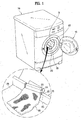
- FIG. 1 is a perspective diagram of a washing apparatus according to a first embodiment of the present invention
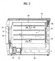
- FIG. 2 is a cross-sectional diagram of a washing apparatus according to a first embodiment of the present invention
- FIG. 3 is a front diagram of an interior of a washing apparatus according to a first embodiment of the present invention.
- FIG. 4 is a projected perspective diagram of a wet cloth pad
- FIG. 5 is a projected perspective diagram of another wet cloth pad of a washing apparatus according to a first embodiment of the present invention.
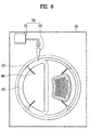
- FIG. 6 is a front diagram of an interior of a washing apparatus according to a second embodiment of the present invention.
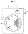
- FIG. 7 is a front diagram of an interior of a washing apparatus according to a third embodiment of the present invention.
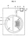
- FIG. 8 is a front diagram of an interior of a washing apparatus according to a third embodiment of the present invention, in which another example of a location of a heating part is shown;
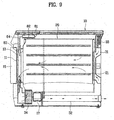
- FIG. 9 is a cross-sectional diagram of a washing apparatus according to a fourth embodiment of the present invention.
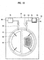
- FIG. 10 is a front diagram of an interior of a washing apparatus according to a fourth embodiment of the present invention.
- FIG. 11 is a perspective diagram of a dirt transfer cloth.
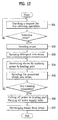
- FIG. 12 is a flowchart of a method of controlling a washing apparatus according to a fourth embodiment of the present invention.
- FIG. 13 is a cross-sectional diagram of a washing apparatus according to a fifth embodiment of the present invention.
- FIG. 14 is a schematic cross-sectional diagram of an interior of a washing apparatus according to a fifth embodiment of the present invention.
- FIG. 15 is a flowchart of a method of controlling a washing apparatus according to a fifth embodiment of the present invention.
- FIG. 16 is a cross-sectional diagram of a washing apparatus according to a sixth embodiment of the present invention.
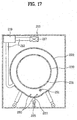
- FIG. 17 and FIG. 18 are schematic cross-sectional diagrams of an interior of a washing apparatus according to a sixth embodiment of the present invention.
- FIG. 19 is a flowchart of a method of controlling a washing apparatus according to a sixth embodiment of the present invention.
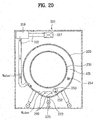
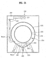
- FIG. 20 and FIG. 21 are schematic cross-sectional diagrams of an interior of a washing apparatus according to a seventh embodiment of the present invention.
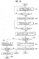
- FIG. 22 is a flowchart of a method of controlling a washing apparatus according to a seventh embodiment of the present invention.
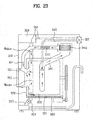
- FIG. 23 is a cross-sectional diagram of a washing apparatus according to an eighth embodiment of the present invention.
- FIG. 24 and FIG. 25 are schematic cross-sectional diagrams of an interior of a washing apparatus according to an eighth embodiment of the present invention.
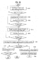
- FIG. 26 is a flowchart of a method of controlling a washing apparatus according to an eighth embodiment of the present invention.
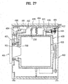
- FIG. 27 is a cross-sectional diagram of a washing apparatus according to a ninth embodiment of the present invention.
- FIG. 28 is a schematic cross-sectional diagram of an interior of a washing apparatus according to a ninth embodiment of the present invention.
- FIG. 29 is a perspective diagram of a steam providing unit of a washing apparatus according to a ninth embodiment of the present invention.
- FIG. 30 is a perspective diagram of a detergent supplying unit of a washing apparatus according to a ninth embodiment of the present invention.
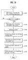
- FIG. 31 is a flowchart of a method of controlling a washing apparatus according to a ninth embodiment of the present invention.
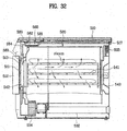
- FIG. 32 is a cross-sectional diagram of a washing apparatus according to a tenth embodiment of the present invention.
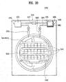
- FIG. 33 is a front diagram of an interior of a washing apparatus according to a tenth embodiment of the present invention.
- FIG. 34 is a perspective diagram of a laundry rack of a washing apparatus according to a tenth embodiment of the present invention.
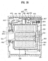
- FIG. 35 is a cross-sectional diagram of a washing apparatus according to an eleventh embodiment of the present invention.
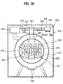
- FIG. 36 is a schematic cross-sectional of an interior of a washing apparatus according to an eleventh embodiment of the present invention.
- FIG. 37 is a schematic cross-sectional diagram of another example of the interior in FIG. 36.
- a washing apparatus is to collectively carry out dry cleaning on a great quantity of laundries using a wet pad cloth of a dry-cleaning kit only.
- the washing apparatus includes a general washing machine, a washer/dryer, or a laundry dryer.
- the washing apparatus may be a laundry dryer for example.
- FIGs. 1 to 5 show a washing apparatus according to a first embodiment of the present invention.
- a washing apparatus includes a body 10, a drum 20, and a wet pad cloth 60.
- the body 10 forms an exterior of the washing apparatus.
- An entrance 11 for laundry input/output is provided to a front side of the body 10, and a rim 13 is provided to the entrance 11.
- the entrance 11 is open/closed by a door 15.
- a motor 17 for rotating the drum 20, as shown in FIG. 2, is provided to an inside bottom part of the body 10.
- a hot air supply pipe 31 for a hot air flow and a hot air discharge pipe 32 for discharging a hot air flowing in the drum 20 are provided within the body 10.
- a drying heater 33 is provided to the hot air supply pipe 31, and a blower fan 34 is provided to the hot air discharge pipe 32.
- the drum 20 is rotatably provided within the body 10, and an opening for the laundry input/output is provided toward the entrance 11.
- At least one agitation piece 21 is provided to an inner wall of the drum 20 to agitate laundry for smooth drying.
- the wet pad cloth 60 is provided within the drum 20.
- the wet pad cloth 60 contains moisture and fragrance inside to diffuse them when subject to heat.
- one wet pad cloth 60 is provided, although more than one may be provided.
- the or each wet pad cloth 60 may be formed of a material enabling various kinds of dirt attached to the laundry to be smoothly transferred.
- the wet pad cloth 60 is in the present embodiment detachably provided to the agitation piece 21.
- a loading part is provided to the agitation piece 21 to install the wet pad cloth 60.
- the loading part includes a loading recess 22 and a fixing holder 23.
- the loading recess 22 having a prescribed height is recessed from a surface of the agitation piece 21 to allow one end of the wet pad cloth 60 to be fitted therein.
- the fixing holder 23 is assembled to the loading recess 22 to fix the wet pad cloth 60 thereto and to open/close the loading recess 22.
- one end of the fixing holder 23 is hinged to the loading recess 22 and a hook 24 is provided to the other end of the fixing holder 23 for hooking into the loading recess 22.
- a hanging recess 25 is provided to a corresponding portion of the loading recess 22 to catch the hook 24.
- the hook may protrude from the loading recess 22 and the hanging recess can be provided to the fixing holder 23.
- hooks are provided to both ends of the fixing holder 23 and hanging recesses are formed to both sides of the loading recess 22 confronting the corresponding hooks, respectively.
- a guide 61 as shown in FIG. 4, is provided in one body to one end of the wet pad cloth 60 and a fitting recess 26 is provided to a topside of the agitation piece 21 so that the guide 61 can be fitted therein.
- the drum 20 is hermetically sealed from an external environment so that dry cleaning can be performed within an entire inner space of the drum 20.
- the dry cleaning means a series of cycles for refreshing the laundries. Yet, the dry cleaning may include a series of cycles for removing various kinds of dirt from the laundries.
- the wet pad cloth 60 evenly comes into contact with the entire laundries to enhance a dry-cleaning effect.
- the wet pad cloth 60 is loaded in the loading recess 22 of each of the agitation pieces 21 within the drum 20.
- the number of the wet pad cloths 60 to be loaded preferably depends on a quantity of the laundry to be dry-cleaned.
- one wet pad cloth 60 is loaded.
- two wet pad cloths 60 are loaded.
- three wet pad cloths 60 are loaded.
- the number of the wet pad cloths 60 to be loaded depends on the quantity of the laundry.
- the wet pad cloths 60 are symmetrically provided to confronting sites, top and bottom sites, or right and left sites within the drum 20 so that the steam and fragrance can be evenly diffused within the drum 20 overall.
- the wet pad cloths 60 are fixed thereto by the fixing holders 23, respectively. Thus, the wet pad cloths 60 can be prevented from being separated from the loading recesses 22 during rotation of the drum 20.
- the laundry to be dry-cleaned is put in the drum 20 and the door 15 is closed. Once a dry cleaning mode is selected, the drying heater 33 and the blower fan 34 are driven to supply hot air or heat to the drum 20.
- the hot air introduced in the drum 20 makes the or each wet pad cloths 60 diffuse the fragrance and steam.
- the fragrance and steam diffused from the respective wet pad cloths 60 can be evenly provided to the drum 20 overall.
- the laundry within the drum 20 is provided with the fragrance and steam diffused from the respective wet pad cloths 60 to be dry-cleaned.
- new wet pad cloths 60 are loaded on the corresponding agitation pieces 21, respectively to execute a series of the aforesaid processes.
- FIG. 5 is a projected perspective diagram of another wet cloth pad of a washing apparatus according to a first embodiment of the present invention.
- the wet pad cloth 60 is loaded on an inner wall of the drum 20 instead of the agitation piece 21.
- a loading part is provided to the inner wall of the drum 20 to make the wet pad cloth 60 detachable.
- the loading part may include the same loading recess 22 and fixing holder 23 of the first embodiment of the present invention. Yet, considering the drum 20 is made of metal, the loading part has difficulty in forming the loading recess 22.
- a guide 61 is provided in one body to one end of the wet pad cloth 60 and a receiving part 27 is provided to the inner wall of the drum 20.
- the receiving part 27 is formed in a manner of protruding from two portions of the inner wall to be bent, thereby having a rail shape.
- a portion of the inner wall of the drum 20 may be concavely bent to form a rail type receiving part 27.
- FIG. 6 is a front diagram of an interior of a washing apparatus according to a second embodiment of the present invention.
- a second embodiment of the present invention includes the elements of the first embodiment of the present invention and further includes a separate fragrance spraying unit 70.
- the fragrance spraying unit 70 enables additionally provision of fragrance for dry cleaning into the drum 20.
- the diffused fragrance from the wet pad cloth 60 may not be evenly diffused into the laundry overall but is discharged outside via the hot air discharge pipe 32. Hence, there may not be sufficient fragrance.
- the present embodiment has the fragrance spraying unit 70 in addition.
- the fragrance spraying unit 70 includes a fragrance storage box 71 for storing fragrance therein and a nozzle type fragrance spray part 72 for spraying the fragrance stored in the fragrance storage box 71 into the drum 20.
- the fragrance spray part 72 may be connected to a pump or the like to forcibly jet the fragrance stored in the fragrance storage box 71 into the drum 20. Instead, the fragrance spray part 72, as shown in FIG. 6, employs a simple valve configuration to spray the fragrance by turning on/off a pipe.
- FIG. 7 and FIG. 8 schematically show an interior of a washing apparatus according to a third embodiment of the present invention.
- a third embodiment of the present invention includes the elements of the first embodiment of the present invention and further includes a separate steam providing unit 80.
- the diffused steam from the wet pad cloth 60 may fail to be evenly diffused into the laundry overall but is discharged outside via the hot air discharge pipe 32. In short insufficient steam may be available.
- the presently described embodiment has steam providing unit 80 provided in addition.
- the steam providing unit 80 includes a water storage part 81 for storing a prescribed amount of water therein, a heating part for generating steam by evaporating the water stored in the water storage part 81, and a nozzle type steam spray part 83 for spraying the generated steam into the drum 20.
- the heating part 82 is a heater for generating heat by electricity impression.
- the drying heater 33 can be used as the heating part 82.
- the heating part 82 can have a configuration enabling to evaporate water flowing in a steam supply pipe 84 connecting the water storage part 81 and the steam spray part 83 by heating a portion of the steam supply part 84.
- the heating part 82 as shown in FIG. 8, can be provided within the water storage part 81.
- the heating part 82 may be a coil or sheath heater.
- the steam spray part 83 can be connected to a pump or the like to enable the steam, which is generated from evaporating the water flowing through the steam supply pipe 84, to be forcibly sprayed into the drum 20.
- the steam spray part 83 can employ a simple valve configuration to spray the steam by turning on/off a pipe as well.
- the washing apparatus is configured to enable the separate steam or fragrance supply like the second or third embodiment of the present invention, the wet pad cloths containing the steam and fragrance therein may not be necessary.
- a washing apparatus is characterized in carrying out dry cleaning effectively without using a wet pad cloth.
- a washing apparatus includes a body 10, a drum 20, and a steam providing unit 80.
- the body 10 forms an exterior of the washing apparatus.
- An entrance 11 is provided to a front side of the body 10, the entrance 11 being open/closed by a door 15.
- a rim 13 is provided to an inner circumference of the entrance 11 to seal up the door 15 and the entrance 11.
- the drum 20 is rotatably provided within the body 10.
- the steam providing unit 80 is configured to diffuse a prescribed amount of steam into the drum 20 for dry cleaning. At least one steam providing unit 80 is provided.
- the or each steam providing unit 80 includes a heating part 82 for generating steam from evaporating water by heat at high temperature, a steam supply pipe 84 for a flow of the steam, a steam spray part 83 for diffusing the steam flowing via the steam supply pipe 84 into the drum 20, and a water storage part 81 for storing a prescribed amount of water therein for generation of the steam.
- the steam spray part 83 has a nozzle shape to enable smooth spray of the steam, and a steam outlet is provided within the drum 20.
- the steam outlet of the steam spray part 83 is perforated into the rim 13 to be exposed to an inside of the drum 20.
- the water storage part 81 is connected to a water supply valve 17 connected to a service pipe or the like to enable automatic water supply from outside.
- the heating part 82 constructing the steam providing unit 80 may include a coil heater enclosing the steam supply pipe 84. In the embodiment of FIG.8 the heating part 82 is provided within the water storage part 81.
- the heating part 82 may include a sheath heater enabling direct heating of the water stored in the water storage part 81 for steam generation.
- the steam providing unit 80 may further includes a water level sensor 85 for sensing the level of the water stored in the water storage part 81.
- the heating part 82 may excessively generate the heat. If there is too much water in the water storage part 81, it takes a long time to evaporate the water for the steam generation.
- the water level sensor 85 allows a uniform level of the water to be stored in the water storage part 81. In this case, the uniform level is enough for the efficient steam generation.
- water supply to the water storage part 81 is cut off. If the water level measured by the water level sensor 85 is lower than the reference value, inflow of water to the water storage part 81 is enabled.
- a washing apparatus according to the fourth embodiment of the present invention further includes a detergent supplying unit 90 to enhance the dry cleaning effect.
- the detergent supplying unit 90 may be unnecessary. However the efficiency of dry cleaning without using a detergent may be too low. Hence, in this embodiment the detergent supplying unit 90 is further included to supply the detergent to the drum 20.
- a suitable detergent is a solvent mixed with a petroleum solvent.
- Fragrance may be added to the detergent for application to the laundry to be dry-cleaned.
- the dry cleaning not only refreshes the laundry but also provides fragrance to the laundry, thereby enhancing user satisfaction.
- the detergent supplying unit 90 includes a detergent storage box 91 for storing the dry-cleaning detergent therein.
- the detergent storage box 91 is provided within the body to enable detergent supplement.
- the detergent supplying unit 90 includes a detergent spray part 93 for spraying the detergent stored in the detergent storage box 91 into the drum 20.
- a detergent outlet of the detergent spray part 93 is perforated into the rim 13 to be exposed to the inside of the drum 20 together with the steam spray part 83.
- the detergent spray part 93 can be connected to a pump or the like to enable to forcibly spray the detergent into the drum 20.
- the detergent spray part 93 as shown in the drawing, can employ a simple valve configuration to spray the detergent by turning on/off a pipe as well.
- the detergent provided via the detergent supplying unit 90 may not contain the petroleum based solvent but the detergent only.
- At least one fragrance spraying unit 70 for providing the fragrance may be provided to the washing apparatus of the present invention instead of the supplying the fragrance from the detergent supplying unit 90.
- the detergent supplying unit 90 and the fragrance spraying unit 70 can be separately provided to the washing apparatus of the present invention.
- the washing apparatus according to the fourth embodiment of the present invention further includes a dirt transfer cloth 50.
- the dirt transfer cloth 50 is formed of a fabric material more efficient in transferring the dirt thereto than the laundry.
- the dirt transfer cloth 50 may be inserted into the drum 20 operated for dry cleaning.
- the dirt transfer cloth 50 is detachably secured within the drum 20.
- the dirt transfer cloth 50 is tangled with the laundry in the course of the dry cleaning and plays a role in transferring the dirt out of a specific portion of the laundry only. To enable the dirt transfer cloth 50 to come into contact with more of the laundry, it is advantageous that the dirt transfer cloth 50 and the laundry move independently separately moved.
- the present invention is characterized in that the dirt transfer cloth 50 is secured to an inside of the drum 20.
- the dirt transfer cloth 50 is secured to the agitation piece 21 for smooth agitation of the laundry.
- the dirt transfer cloth 50 can secured to the inner wall of the drum 20.
- a method of controlling a washing apparatus according to the fourth embodiment of the present invention is explained with reference to a flowchart in FIG. 12 as follows.
- a controller (not shown in the drawing) controlling an operation of a laundry dryer keeps checking a presence or non-presence of a request for a dry-cleaning operation (S11).
- the controller decides whether the operation selected by the user is for the dry cleaning or a general laundry drying. Hence, the controller detects the presence of the request for dry cleaning.
- the controller requests an input of the laundry to be dry-cleaned.
- the user inputs the laundry to be dry-cleaned to the drum 20, closes the door 15, and then selects a continuous execution of the dry-cleaning operation.
- At least one or more dirt transfer cloths 50 may be secured to the agitation pieces 21 within the drum 20.
- the user may request the dry-cleaning operation so that the controller can immediately control the various elements for the dry-cleaning operation.
- the drum is rotated (S13) and the detergent supplying unit 90 is controlled to supply the detergent stored in the detergent storage box 91 to the drum 20 (S13).
- the detergent keeps being sprayed during the execution of the dry-cleaning operation.
- the detergent may be controlled to stop being sprayed when starting to provide the steam within the drum 20.
- the water level sensor 85 and the water supply valve 17 closing/opening the water supply pipe cooperate with the controller to maintain a constant level of the water stored within the water storage part 81.
- the water supply valve is turned on to enable the corresponding water supply.
- steam supplied to the drum 20 activates the detergent involved in the laundry to separate the dirt from the laundry, whereby the laundry is refreshed.
- the fragrance included in the detergent is adsorbed to the laundry to remove odors of the laundry and solvent.
- the controller After completion of the dry cleaning through a series of the aforesaid processes, the controller turns off the water supply valve 17 as well as cutting off the power supplied to the heating part 82 (S16).
- the controller then causes steam remaining within the drum 20 to be discharged from the drum 20 to protect the user from danger such as a burn caused by the high-temperature steam. This may be achieved by driving the blower fan 34.
- blower fan 34 is rotated so that the steam within the drum 20 can be discharged outside the body 10 via the hot air discharge pipe 32.
- the drying heater 33 it is preferable to control the drying heater 33 not to generate heat. Yet, the dry-cleaned laundry can be dried by generating heat from the drying heater 33.
- new dirt transfer cloths 50 are loaded in the drum 20, to repeat the aforesaid processes.
- a washing apparatus according to the fourth embodiment of the present invention is applicable to other kinds of apparatuses as well as the laundry dryer.
- the washing apparatus according to the fourth embodiment of the present invention is applicable to a washer/dryer, a general drum type washing machine, and the like.
- a fifth embodiment of the present invention is characterized in applying the configuration of the fourth embodiment of the present invention to a dryer/washer.
- a washing apparatus includes a body 110, an outer tub 120, a drum 130, a waster supply pipe 112, and a detergent supplying unit 190.
- the body 110 forms an exterior of a washer/dryer.
- An entrance 111 is provided to a front side of the body 110, the entrance 111 being open/closed by a door 115.
- a rim 113 is provided to an inner circumference of the entrance 111 for seal-up between the door 115 and the entrance 111.
- the outer tub 120 Disposed within the body 110 are the outer tub 120 and a drying unit providing heated air to an inside of the outer tub 120.
- the drying unit includes a drying duct 141, a drying heater 143 provided to a pipe of the drying duct 141, and a blower fan 144 for forcible air circulation.
- An air inlet of the drying duct 141 is connected to a lateral side of the outer tub 120 and an air outlet of the drying duct 141 is connected to a topside of the outer tub 120.
- the drum 130 is rotatable within the outer tub 120.
- the water supply pipe 112 is configured to supply water to the outer tub 120.
- One end of the water supply pipe 112 is exposed outside the body 110 to be connected to a service pipe (not shown in the drawing).
- a detergent box 119 storing various detergents necessary for washing to the pipe path of the water supply pipe 112.
- the detergent supplying unit 190 is configured to spray a dry-cleaning detergent into the drum 130.
- the detergent supplying unit 190 includes a detergent storage box 191 for storing the dry-cleaning detergent therein and a detergent spray part 193 for spraying the detergent stored in the detergent storage box 191 in a vaporized state.
- a detergent outlet of the detergent spray part 193 is perforated into the rim 113 to be exposed to the inside of the drum 130.
- the detergent spray part 193 can be connected to a pump or the like to enable to forcibly spray the detergent stored in the detergent storage box 191 into the drum 130.
- the detergent spray part 193, as shown in the drawing, employs a simple valve configuration to optionally spray the detergent via a separate valve 194.
- the detergent storage box 191 and the detergent box 119 provided to the pipe path of the water supply pipe 112 can be separately provided. Alternatively, it is preferable that they are formed in one body to enhance efficiency of an overall installation space.
- the detergent stored in the detergent storage box 191 includes a solvent mixed with a petroleum solvent.
- fragrance is further added to the detergent to be given to the laundry.
- the washing apparatus according to the fifth embodiment of the present invention further includes a water heater 160.
- the water heater 160 is provided to a bottom part within the outer tub 120 to generate steam by heating water.
- a method of controlling a washing apparatus according to the fifth embodiment of the present invention is explained with reference to a flowchart in FIG. 15 as follows.
- the detergent supplying unit 190 sprays the dry-cleaning detergent onto the laundry inputted to the drum 130.
- an amount of the detergent sprayed into the drum 130 is set up not to soak the laundry therein.
- the dry-cleaning detergent is evenly coated on the laundry overall.
- the drum 130 may keep being rotated in one rotational direction. Preferably, it is controlled to alternately repeat to rotate the drum 130, clockwise and counter clockwise.
- the water heater 160 generates heat.
- the water collected in the bottom part of the outer tub 120 is evaporated to generate the steam within the drum 130.
- the water remains in a state of being supplied prior to inputting the laundry to the drum 130.
- the water was supplied at the water level not to flood the bottom part of the drum 130.
- the above-generated steam activates the detergent infiltrated into the laundry to enable smooth separation of the dirt.
- a time sufficient for enabling the smooth separation of the dirt from the laundry is provided after completion of the dry-cleaning detergent spray and the steam supply.
- water is injected into the drum 130 via the water supply pipe 112 to remove the dirt separated from the laundry.
- an amount of the water injected into the drum 130 is preferably set small not to soak the laundry.
- the washing apparatus since the above-explained washing apparatus according to the fifth embodiment of the present invention generated the steam by evaporating the water supplied to the bottom part within the outer tub 120, the level of the water should be maintained constant.
- a washing apparatus includes a body 210, an outer tub 220, a drum 230, a water heater 260, and a water supply pipe 212.
- the body 210 forms an exterior of the washing apparatus.
- An entrance 211 is provided to a front side of the body 210. And, the entrance 211 is open/closed by a door 215.
- the outer tub 220 is provided within the body 210, and the drum 230 is rotatably provided within the outer tub 220.
- a multitude of perforated holes 231 are formed in a circumference of the drum 230 to allow water and steam to flow into the drum 230.
- the water heater 260 is provided to a bottom part within the outer tub 220 to heat the water supplied to the outer tub 220.
- a part (herein after called loading part) 221, where the water heater 260 is loaded, is provided by a concave portion of the outer tub 220 and is connected to a drainpipe 223 for draining the water after completion of washing. And, a drain valve 225 is provided to the drainpipe 223.
- the water heater 260 enables steam generation as well as operates to heat the water.
- the steam for refreshing the laundry is generated using the water heater 260 instead of using a separate steam generator.
- the water supply pipe 212 is a pipe path through which the water flows.
- the water supply pipe 212 guides to supply the water provided from the service pipe or the like via the water supply valve 217 to an inside of the outer tub 220.
- a detergent box 219 for storing a detergent is provided to the pipe path of the water supply pipe 212 so that the detergent can be included in the water flowing into the outer tub 220.
- the detergent box 219 is provided to an upper space within the body 210 to enable a detergent input.
- a water outlet of the water supply pipe 212 for supplying the water to a part provided with the water heater 260 is connected to the upper part of the outer tub 220, whereby the laundry to be dry-cleaned maybe soaked in the supplied water.
- the water supply pipe 212 is connected to the outer tub 220 in the vicinity of the part provided with the water heater 260, i.e., the loading part 221.
- the water outlet of the water supply pipe 221, as shown in FIG. 17, is preferably connected to a circumference of the bottom part of the outer tub 220.
- the water outlet of the water supply pipe 212 is bent upward from a bottom part thereof to prevent the splash of the water.
- a level of the water supplied to the loading part 221 within the outer tub 220 is set up not to exceed a bottom of the drum 230.
- the water may flow in the drum 230 via the perforated holes formed on the outer circumference of the drum 230 to soak the laundry.
- a series of configurations are further provided to sense the level of the water supplied to the outer tub 220.
- the present invention is characterized in further including a water level sensing unit provided to a bottom space within the outer tub 220.
- the water level sensing unit senses the water level within the loading part 221 to control the water supply valve 217 and the water heater 260, whereby the water level can be maintained uniform within the loading part.
- the water level sensing unit may include a pressure sensor generally used in water level detection. Yet, considering that an amount of the water for the dry-cleaning operation is extremely smaller than a water amount necessary for washing, it is disadvantageous to use the pressure sensor having a relatively great deviation of a water supply amount.
- the sensing unit includes a temperature sensor 251 checking whether to supply the water by sensing a peripheral temperature.
- the temperature sensor 251 is located higher than the water heater 260 as well as lower than the bottom of the drum 230.
- the water heater 260 By enabling the water heater 260 to generate heat only if submerged under the water, it is able to prevent excessive heat generation of the water heater 260.
- the temperature sensor 251 is placed between the water heater 260 and the bottom of the drum 230 to leave a maximum distance from the water heater 260.
- Such a configuration is provided to minimize the problem that the temperature sensor 251 may fail in sensing a temperature precisely due to the heat generation of the water heater 260.
- a controller (not shown in the drawing) controlling an operation of a drum type washing machine keeps checking a presence or non-presence of a request for a dry-cleaning operation (S110).
- the controller decides whether the operation selected by the user is for the dry cleaning or a general laundry washing. Hence, the controller detects the presence of the request for dry cleaning.
- the controller requests an input of the type of laundry to be dry-cleaned.
- the user inputs the laundry to be dry-cleaned to the drum 230, closes the door 215, and then selects a continuous execution of the dry-cleaning operation.
- the user may request the dry-cleaning operation so that the controller can immediately control the various elements for the dry-cleaning operation.
- the controller controls the water supply valve 217 to enable a water supply to the water supply pipe 212 (S120).
- the water is introduced into the outer tub 220 via the water supply pipe 212.
- the water outlet of the water supply pipe 212 is located under the outer tub 220, it is able to prevent the water from being directly injected to an outside of the drum 230.
- it is able to prevent the laundry from being wet as well.
- the water supplied to the outer tub 220 is introduced into the loading part 221 provided with the water heater 260 to gradually rise from the initial state in FIG. 17 toward an upper part of the loading part 221. In doing so, the pipe path of the drainpipe 223 connected to the loading part 221 is cut off.
- the controller keeps receiving the sensing signals for the temperature variation from the temperature sensor 251 to check whether the sensed temperature is instantly varies over a reference temperature value (S130).
- the reference temperature value is a value resulting from an instant and abrupt temperature variation instead of a uniform variation of a temperature increase that varies in proportion to a temperature increase.
- the reference temperature value can be set to ⁇ 2°C and the like.
- the temperature of the water is about 15°C and that the temperature sensor 251 performs its temperature sensing under an environment at about 30°C, if the water is supplied to reach the temperature sensor 251, the temperature 251 detects a temperature drop on measuring the temperature of the water. In such a manner, a current level of the water can be detected.
- the controller controls the water supply valve 217 to stop supplying the water.
- a corresponding state is shown in FIG. 18.
- the heat generation of the water heater 260 evaporates the water within the outer tub 220.
- the generated steam by the evaporation is introduced into the drum 230 via the perforated holes 231 to refresh the laundry within the drum 230.
- the drum 230 is being rotated to agitate the laundry within the drum 230, which helps the laundry refreshed more smoothly.
- the steam generation according to the above process keeps occurring during a dry-cleaning setup time. If the dry-cleaning time is set longer than the time taken for the water in the bottom part within the outer tub 220 to be entirely evaporated, shortage of the water takes place to rapidly raise the temperature of the portion provided with the water heater 260.
- the dry-cleaning time can be set shorter than the evaporation time of the water.
- an amount of the steam supplied for the dry cleaning may become in short to lower dry-cleaning performance. It is also able to increase a water storage amount by modifying a shape of the loading part 221 within the outer tub 120. In such a case, the shape modification needs to redesign other elements.
- overheating occurrence is checked by sensing the temperature continuously using the temperature sensor 251 in the same manner of an early stage of the water supply while the steam is generated (5150).
- a timing point of stopping the water supply is decided by sensing the temperature variation in the course of re-executing the water supply to prevent the laundry from being wet by the oversupply of the water.
- the power applied to the water heater 260 is cut off (S170).
- a generated steam amount according to the heat generation time of the water heater 260 is previously acquired through a test and the like and the acquired value is previously set up, by which it is able to decide the steam amount through such a simple process as a process of counting the heat generation time of the water heater 260 and the like.
- a humidity sensor (not shown in the drawing) for checking the amount of the steam within the outer tub 220 is further provided to an inner space of the outer tub 220, whereby the power applied to the water heater 260 is cut off if the humidity sensed by the humidity sensor reaches a predefined humidity.
- the drain valve 225 is controlled to open the drainpipe 223 so that the remaining water within the loading part 221 is discharged (S180). Thus, the operation for the dry cleaning is terminated.
- a washing apparatus is characterized in using an electrode sensor instead of the temperature sensor of the sixth embodiment of the present invention, which is explained in detail as follows.
- a washing apparatus includes a body 210, an outer tub 220, a drum 230, a water heater 260, a water supply pipe 212, an electrode sensor, and a controller.
- the body 210, outer tub 220, drum 230, water heater 260, and water supply pipe 212 have the same configurations of the sixth embodiment of the present invention.
- the electrode sensor includes a first electrode 252 and a second electrode 253.
- the first and second electrodes 252 and 253 play a role in sensing that the level of the water supplied to the bottom part within the outer tub 200 avoids exceeding the bottom of the drum 230 and are placed between the water heater 260 and the drum 230.
- the first electrode 252 is located in the vicinity of the water heater 260 and the second electrode 253 is located above the first electrode 252. Hence, in case that the level of the water exceeds a setup water level, an electric current is turned on between the first and second electrodes 252 and 253.
- controls of the water supply valve 225 and the water heater 260 are executed in case that electric current is turned on between the first and second electrodes 252 and 253.
- the first electrode 252 is preferably located above the water heater 260 and the second electrode is preferably located below the bottom of the drum 230.
- the electrode sensor is provided to one site opposite to the other site connected to the water outlet of the water supply pipe 212 in the space having the water heater 260 provided thereto. Hence, it is able to prevent a malfunction of driving the water heater 260 to generate heat when the electrodes 252 and 253 are shorted by the splashed water prior to the completion of supplying the water to the predefined water level.
- the water heater 260 by enabling the water heater 260 to generate heat only if the water heater is fully submerged under the water, it is able to prevent the overheating of the water heater 260.
- the controller plays a role in controlling the heat generation of the water heater 260 by checking the presence or non-presence of the short circuit between the electrodes 252 and 253 optionally.
- the embodiment of the present invention further includes a humidity sensor 254 in the inner space of the outer tub 220.
- the humidity sensor 254 checks an amount of the generated stream within the outer tub 220 to enable the control of the water heater 260, thereby enhancing refresh performance on the laundry through appropriate humidity maintenance.
- a controller (not shown in the drawing) controlling an operation of a drum type washing machine keeps checking a presence or non-presence of a request for a dry-cleaning operation (S210).
- the controller decides whether the operation selected by the user is for the dry cleaning or a general laundry washing. Hence, the controller detects the presence of the request for dry cleaning.
- the controller In case of the presence of the request for the dry-cleaning operation, the controller requests an input of the laundry to be dry-cleaned.
- the user inputs the laundry to be dry-cleaned to the drum 230, closes the door 215, and then selects a continuous execution of the dry-cleaning operation.
- the user may request the dry-cleaning operation so that the controller can immediately control the various elements for the dry-cleaning operation.
- the controller controls the water supply valve 217 to enable a water supply to the water supply pipe 212 (S220).
- the water is introduced into the outer tub 220 via the water supply pipe 212.
- the water outlet of the water supply pipe 212 is located under the outer tub 220, it is able to prevent the water from being directly injected to an outside of the drum 230.
- it is able to prevent the laundry from being wet as well.
- the water supplied to the outer tub 220 is introduced into the loading part 221 provided with the water heater 260 to gradually rise toward an upper part of the loading part 221. In doing so, the pipe path of the drainpipe 223 connected to the loading part 221 is cut off.
- the controller keeps checking a presence or non-presence of short circuit between the electrodes 252 and 253 (S230).
- the water level As the level of the supplied water gradually rises, the water level, as shown in FIG. 20, reaches the first electrode 252. As the water keeps being supplied, so the water level exceeds the first electrode 252 to reach the second electrode 253.
- the controller decides that the level of the water has reached the necessary water level and then controls the water supply valve 217 to stop supplying the water.
- the controller allows power to be supplied to the water heater 260 (S240) so that the hot steam for the dry cleaning can be produced by the heat generated from the water heater 260.
- the heat generation of the water heater 260 evaporates the water within the outer tub 220.
- the generated steam by the evaporation is introduced into the drum 230 via the perforated holes 231 of the drum 230 to refresh the laundry within the drum 230.
- the drum 230 is being rotated to agitate the laundry within the drum 230, which enhances a refreshing effect of the laundry.
- the steam generation according to the above process keeps occurring during a dry-cleaning setup time. If the dry-cleaning time is set longer than the time taken for the water in the bottom part within the outer tub 220 to be entirely evaporated, shortage of the water takes place to rapidly raise the temperature of the portion provided with the water heater 260.
- the dry-cleaning time can be set shorter than the evaporation time of the water.
- an amount of the steam supplied for the dry cleaning may become in short to lower dry-cleaning performance. It is also able to increase a water storage amount by modifying a shape of the loading part 221 within the outer tub 220. In such a case, the shape modification needs to redesign other elements.
- the presence or non-presence of the short circuit between the electrodes keeps being checked in the same manner of an early stage of the water supply while the steam is generated (S250).
- a timing point of stopping the water supply is decided by keeping checking the presence or non-presence of the short circuit between the electrodes in the course of re-executing the water supply to prevent the laundry from being wet by the oversupply of the water.
- the power applied to the water heater 260 is cut off (S270).
- the steam amount can be confirmed through a sensing value of the humidity sensor 254 provided within the outer tub 220.
- the predefined humidity means a steam amount most appropriate for refreshing the laundry, which can be acquired by a test value on which no limitation is put.
- a generated steam amount according to the heat generation time of the water heater 260 can be previously acquired through a test and the like and the acquired value is previously set up, by which it is able to decide the steam amount through such a simple process as a process of counting the heat generation time of the water heater 260 and the like.
- the drain valve 225 is controlled to open the drainpipe 223 so that the remaining water within the loading part 221 can be discharged (S280). Thus, the operation for the dry cleaning is terminated.
- the water for the use of the steam generation is preferentially supplied to the water supply pipe in the fifth to seventh embodiments of the present invention, it is difficult to maintain a precise water level.
- the water supplement is supposed to amount to a small quantity. Yet, the water supplement could be excessively made.
- a washing apparatus is characterized in maintaining a precise level of water supplied for steam generation, which is explained in detail as follows.
- a washing apparatus includes a body 310, an outer tub 320, a drum 330, a water heater 360, a water supply pipe 312, a drying duct 341, and a cooling water supply pipe 345.
- the body 310 forms an exterior of the washing apparatus.
- An entrance 311 is provided to a front side of the body 210. And, the entrance 311 is open/closed by a door 315.
- the outer tub 320 is provided within the body 310, and the drum 330 is rotatably provided within the outer tub 320.
- a multitude of perforated holes 331 are formed in a circumference of the drum 330 to allow water and steam to flow into the drum 330.
- the water heater 360 is provided to a bottom part within the outer tub 320 to heat the water supplied to the outer tub 320.
- a part (herein after called loading part) 321, where the water heater 360 is loaded, is provided by a concave portion of the outer tub 320 and is connected to a drainpipe 323 for draining the water after completion of washing.
- a drain valve 324 opening/closing a pipe path of the drainpipe 323 is provided to the drainpipe 323.
- the water heater 260 enables steam generation as well as operates to heat the water.
- the steam for refreshing the laundry is generated using the water heater 360 instead of using a separate steam generator.
- the water supply pipe 312 is a pipe path through which the water flows.
- the water supply pipe 312 guides to supply the water provided from the service pipe or the like via the water supply valve 317 to an inside of the outer tub 320.
- a detergent box 319 storing a detergent is provided to the pipe path of the water supply pipe 312 so that the detergent can be added to the water flowing into the outer tub 320.
- the detergent box 319 is provided to an upper space within the body 310 to enable a detergent input. And, fragrance used in dry cleaning can be included in the detergent supplied via the detergent box 319.
- a water outlet of the water supply pipe 312 for supplying the water to a part provided with the water heater 360 is connected to the upper part of the outer tub 320, whereby the laundry to be dry-cleaned could be soaked in the supplied water.
- the water supply pipe 312 is connected to the outer tub 320 in the vicinity of the part provided with the water heater 360, i.e., the loading part 321.
- the water outlet of the water supply pipe 321 is preferably connected to a circumference of the bottom part of the outer tub 320.
- the water outlet of the water supply pipe 312 is bent upward from a bottom part thereof to prevent the splash of the water.
- the drying duct 341 is configured to provide hot air to the outer tub 320.
- An air inlet of the drying duct 341 is connected to a lower circumference of the outer tub 320 and an air outlet of the drying duct 341 is connected to an upper circumference of the outer tub 320.
- a drying heater 343 for heating flowing air and a blower fan 344 forcibly blowing to move the air are provided to a pipe path within the drying duct 341.
- cooling water supply pipe 345 is connected to the pipe path of the drying duct 341 and is configured to provide a small amount of cooling water.
- the cooling water supply pipe 345 is connected to a location enabling the cooling water to be directly provided to the bottom part of the outer tub 320, i.e., the air inlet of the drying duct 341.
- the cooling water supply pipe 345 can be configured to be connected to the service pipe via a separate pipe path.
- the cooling water supply pipe 345 is connected to the water supply valve 318 to enable the water supply by a control of the water supply valve 317.
- the water heater 360 generates heat if a level of the water supplied to the outer tub 320 does not exceed the bottom of the drum 330 and is enough for the water heater 360 to be submerged.
- the water is supplied to exceed a height of the bottom of the drum 330, the water is introduced into the drum 330 via the perforated holes 331 of the drum 330 to wet the laundry.
- the excessive heat generation from the water heater 360 can transform the drum 330, outer tub 320 and other various electric/electronic parts.
- the embodiment of the present invention further includes a water level sensor 351 installed in a lower space of the outer tub 320 provided with the water heater 360 to sense the level of the water supplied to the loading part 321.
- the water level sensor351 may be a temperature sensor enabling a water level measurement according to a temperature variation within the loading part 321, an electrode sensor enabling a water level measurement through a confirmation of a short-circuited or cut-off state between a pair of electrodes respectively located in different heights, or a pressure sensor enabling a water level measurement through a confirmation of a pressure of the water.
- the embodiment of the present invention further includes a humidity sensor 352 provided to an inner space of the outer tub 320.
- the humidity sensor 352 checks an amount of the generated steam within the outer tub 320 to enable a control of the water heater 360, thereby enhancing refreshing performance of the laundry thorough appropriate humidity maintenance.
- a controller controlling an operation of the washing apparatus keeps checking a presence or non-presence of a request for a dry-cleaning operation (S310).
- the controller decides whether the operation selected by the user is for the dry cleaning or a general laundry washing. Hence, the controller detects the presence of the request for dry cleaning.
- the controller requests an input of the laundry to be dry-cleaned.
- the user inputs the laundry to be dry-cleaned to the drum 330, closes the door 315, and then selects a continuous execution of the dry-cleaning operation.
- the user may request the dry-cleaning operation so that the controller can immediately control the various elements for the dry-cleaning operation.
- the controller controls the water supply valve 317 to enable a water supply to the water supply pipe 312 (S320).
- the water supply can be performed using both of the water supply pipe 312 and the cooling water supply pipe 345.
- the water is introduced into the outer tub 320 via the water supply pipe 312.
- the water outlet of the water supply pipe 312 is located under the outer tub 320, it is able to prevent the water from being directly injected to an outside of the drum 330.
- it is able to prevent the laundry from being wet as well.
- the water supplied to the outer tub 320 is introduced into the loading part 321 provided with the water heater 360 to gradually rise toward an upper part of the loading part 321. In doing so, the pipe path of the drainpipe 323 connected to the loading part 321 is cut off.
- the controller keeps checking a presence or non-presence of the level of the supplied water using the water level sensor 351.
- the controller controls the water supply valve 317 to stop supplying the water via the water supply pipe 312 but enables a small amount of water to be supplied via the cooling water supply pipe 345 only (S340).
- the predefined first water level corresponds to an installation height of the water heater 360.
- the water flowing through the cooling water supply pipe 345 is introduced into the drying duct 341 to flow in the bottom part within the outer tub 320 along the drying duct 341 and keeps being supplied to the loading part 321.
- the water level keeps being checked by the water level sensor 351 (S350). If it is confirmed that the water level, as shown in FIG. 25, reaches a predefined second water level, the controller controls the water supply valve 317 to stop supplying the water via the cooling water supply pipe 345.
- the predefined second water level means a water level enabling the water heater to be fully submerged under the water but failing to reach the bottom of the drum 330.
- a supply amount e.g., about 0.05 l /min
- the water level gradually rises to minimize a water level deviation.
- the water heater 360 can be prevented from generating excessive heat according to water shortage since the water supply corresponding to a maximum amount is enabled.
- the heat generation of the water heater 360 evaporates the water within the outer tub 320.
- the generated steam by the evaporation is introduced into the drum 330 via the perforated holes 331 of the drum 330 to refresh the laundry within the drum 330.
- the drying heater 343 and the blower fan 344 provided within the drying duct 341 are maintained to stop operating, whereby the steam can be smoothly supplied to the drum 330.
- the drum 330 is being rotated to agitate the laundry within the drum 330, which enhances refreshing performance on the laundry.
- the steam generation according to the above process keeps occurring during a dry-cleaning setup time. If the dry-cleaning time is set longer than the time taken for the water in the bottom part within the outer tub 320 to be entirely evaporated, shortage of the water takes place to rapidly raise the temperature of the portion provided with the water heater 360.
- the dry-cleaning time can be set shorter than the evaporation time of the water.
- an amount of the steam supplied for the dry cleaning may become in short to lower dry-cleaning performance. It is also able to increase a water storage amount by modifying a shape of the loading part 321 within the outer tub 320. In such a case, the shape modification needs to redesign other elements.
- the embodiment of the present invention further proposes that the water level keeps being checked using the water level sensor 351 in the same manner of an early stage of the water supply while the steam is generated (S370).
- the water level confirmed by the water level sensor 351 is lower than a predefined third water level, it is decided that the water is in short. Hence, an additional water supply to the loading part 321 provided with the water heater 360 within the outer tub 320 is performed.
- the water is set up to be supplied via the cooling water supply pipe 345. And, it is preferable that a timing point of stopping the water supply is decided by keeping checking whether the level of the water reaches the second water level using the water level sensor 351 in the course of re-executing the water supply to prevent the laundry from being wet by the oversupply of the water.
- the power applied to the water heater 360 is cut off (S380).
- the steam amount can be confirmed through a sensing value of the humidity sensor 352 provided within the outer tub 320.
- the predefined humidity means a steam amount most appropriate for refreshing the laundry, which can be acquired by a test value on which no limitation is put.
- a generated steam amount according to the heat generation time of the water heater 360 can be previously acquired through a test and the like and the acquired value is previously set up, by which it is able to decide the steam amount through such a simple process as a process of counting the heat generation time of the water heater 360 and the like.
- the drain valve 324 is controlled to open the drainpipe 323 so that the remaining water within the loading part 321 can be discharged (S390). Thus, the operation for the dry cleaning is terminated.
- a ninth embodiment of the present invention is characterized in applying the configuration of the washing apparatus according to the fourth embodiment of the present invention to a dryer/washer configured different from that of the fifth embodiment of the present invention, which is explained in detail with reference to FIGs. 27 to 30 as follows.
- a washing apparatus includes a body 410, an outer tub 420, a drum 430, and a steam providing unit 480.
- the body 410 forms an exterior of the washing apparatus.
- An entrance 411 is provided to a front side of the body 410. And, the entrance 411 is open/closed by a door 415.
- a rim 413 is provided to an inner circumference of the entrance 411 for seal-up between the door 415 and the entrance 411.
- the outer tub 420 is provided within the body 410, and the drum 430 is rotatably provided within the outer tub 420.
- a multitude of perforated holes 431 are formed in a circumference of the drum 430 to allow water and steam to flow into the drum 430.
- the steam providing unit 480 is configured to diffuse a prescribed amount of steam into the drum 430 for dry cleaning. And, at least one or more steam providing units 480 are provided.
- the dry cleaning means not only a series of processes for refreshing the laundry but also a series of processes for removing various kinds of dirt from the laundry.
- the steam providing unit 480 includes a heating part 482 for generating steam from evaporating water by heat at high temperature.
- the steam providing unit 480 includes a steam supply pipe 484 for a flow of the steam generated from the evaporation by the heating part 482.
- the steam providing unit 480 includes a steam spray part 483 for diffusing the steam flowing via the steam supply pipe 484 into the drum 430.
- the steam spray part 483 has a nozzle shape to enable smooth spray of the steam, and a steam outlet is provided within the drum 430.
- a steam outlet is provided within the drum 430.
- the steam outlet of the steam spray part 483 is perforated into the rim 413 to be exposed to an inner space of the drum 430.
- the steam spray part 483 can be connected to a pump or the like to enable the steam, which is generated from evaporating the water flowing through the steam supply pipe 484, to be forcibly sprayed into the drum 430.
- the steam spray part 483 further includes a first open/close valve 486 provided to the steam supply pipe 484 opening/closing a pipe path of the steam supply pipe 484 to spray the steam selectively.
- the steam providing unit 480 includes a water storage part 481 for storing a prescribed amount of water therein to supply the water to the steam supply pipe 484.
- An inlet of the water storage part 481 is connected to a water supply valve 417 connected to a service pipe or the like and an outlet of the water storage part 481 is connected to the steam supply pipe 484.
- the heating part 482 may include a coil heater enclosing the steam supply pipe 484.
- the heating part 482 preferably includes a sheath heater provided within the water storage part 481 to directly heat to evaporate the water stored in the water storage part 481.
- the steam providing unit 480 further includes a water level sensor 485 for sensing a level of the water stored in the water storage part 481.
- the heating part 482 may excessively generate the heat. If the amount of the water stored in the water storage part 481 is excessively sufficient, it takes a long time to evaporate the water for the steam generation. Hence, the water level sensor 485 enables to maintain a uniform level of the water stored in the water storage part 481. In this case, the uniform level is enough for the smooth steam generation.
- water supply to the water storage part 481 is cut off. If the water level measured by the water level sensor 485 is lower than the reference value, supplementary water supply to the water storage part 481 is enabled.
- the washing apparatus according to the ninth embodiment of the present invention further includes a detergent supplying unit 490 to enhance the dry cleaning effect.
- the detergent is a solvent mixed with a petroleum solvent.
- fragrance is further added to the detergent to be given to the laundry to be dry-cleaned.
- the dry cleaning not only refreshes the laundry but also provides the fragrance to the laundry, thereby enhancing user's satisfaction.
- the detergent supplied via the detergent supplying unit 490 may include the fragrance only without the petroleum-based solvent.
- the detergent supplying unit 490 may include at least one fragrance spray part providing the fragrance.
- the detergent supplying unit 490 and the fragrance spray part can be separately provided.
- the detergent supplying unit 490 includes a detergent storage box 491 storing the dry-cleaning detergent therein.
- the detergent storage box 491 is provided within the body 410 to enable detergent supplement.
- the detergent supplying unit 490 includes a detergent spray part 493 for spraying the detergent stored in the detergent storage box 491 into the drum 430 and a detergent supply pipe 494 for guiding the detergent within the detergent storage box 491 to the detergent spray part 493.
- a detergent outlet of the detergent spray part 493 is exposed to the inside of the drum 430.
- a detergent outlet of the detergent spray part 493 is perforated into the rim 413 to be exposed to the inside of the drum 430.
- the detergent spray part 493 can be connected to a pump or the like to enable to forcibly spray the detergent stored in the detergent storage box 491 into the drum 430.
- the detergent spray part 493 further includes a second open/close valve 496 for opening/closing the pipe path of the detergent supply pipe 494 so that the detergent can be selectively sprayed.
- the detergent spray part 493 and the steam spray part 483 can be built in one body.
- the detergent storage box 491 enables to store a washing detergent as well.
- the detergent storage box 491 includes a first storage part 497 storing the dry-cleaning detergent and a second storage part 498 storing the washing detergent.
- the second storage part 498 is connected to the water supply pipe 412 so that a small amount of the water is sprayed into the drum 430 via the detergent spray part 493.
- the washing apparatus according to the present invention further includes a drying unit.
- the drying unit includes a drying duct 441 for providing hot and dry air to the drum 430 and a drying heater 443 for heating the air flowing through the drying duct 441.
- a blower fan 444 forcibly blowing the air within the drying duct 441 is further provided to a pipe path of the drying duct 441.
- a controller controlling an operation of the washing apparatus keeps checking a presence or non-presence of a request for a dry-cleaning operation (S410).
- the controller decides whether the operation selected by the user is for the dry cleaning or a general laundry washing. Hence, the controller detects the presence of the request for dry cleaning.
- the controller requests an input of the laundry to be dry-cleaned.
- the user inputs the laundry to be dry-cleaned to the drum 430, closes the door 415, and then selects a continuous execution of the dry-cleaning operation.
- the user may request the dry-cleaning operation so that the controller can immediately control the various elements for the dry-cleaning operation.
- the second open/close valve 496 is controller to spray the dry-cleaning detergent into the laundry inputted to the drum 430.
- a controller controlling an operation of the washing apparatus keeps checking a presence or non-presence of a request for a dry-cleaning operation (S310).
- the controller decides whether the operation selected by the user is for the dry cleaning or a general laundry washing. Hence, the controller detects the presence of the request for dry cleaning.
- the controller requests an input of the laundry to be dry-cleaned.
- the user inputs the laundry to be dry-cleaned to the drum 330, closes the door 315, and then selects a continuous execution of the dry-cleaning operation.
- the user may request the dry-cleaning operation so that the controller can immediately control the various elements for the dry-cleaning operation.
- an amount of the detergent sprayed into the drum 430 is set up not to soak the laundry therein.
- the detergent includes the solvent and the fragrance.
- the dry-cleaning detergent is evenly coated on the laundry overall.
- the drum 430 may keep being rotated in one rotational direction. Preferably, it is controlled to alternately repeat to rotate the drum 430, clockwise and counter clockwise.
- the water heater 160 is activated to generate the steam (S440) and the generated steam is sprayed into the outer tub (S450).
- the water introduced into the water storage part 481 is evaporated by the generated heat of the heating part 482 and the evaporated water in a steam state is then guided by the steam supply pipe 484 to be sprayed into the space within the outer tub 420.
- the first open/close valve 486 is turned on.
- the steam sprayed into the outer tub 420 is introduced into the drum 430 via the perforated holes 431 of the drum 430 and then keeps being supplied to the laundry to refresh.
- the above-generated steam activates the detergent infiltrated into the laundry to enable smooth separation of the dirt.
- a next process is preferably carried out after a time sufficient for enabling the smooth separation of the dirt from the laundry has passed after completion of the dry-cleaning detergent spray and the steam supply.
- a small amount of water is injected into the drum 430 via the steam spray part 483 or the detergent spray part 493 to remove the dirt separated from the laundry.
- detergent the spray part 493 is configured to face the inside of the drum 430, a series of the process spraying the water into the drum 430 is preferably performed via the detergent spray part 493.
- the water is supplied to the second storage part 498 of the detergent storage box 491 so that the water sprayed into the drum 430 does not include the dry-cleaning detergent.
- an amount of the water injected into the drum 130 is preferably set small not to soak the laundry.
- a series of the process of spraying the water can be carried out prior to supplying the steam to the drum 430.
- the steam plays a role in refreshing the laundry rather than induces the activation of the detergent.
- the dry air is provided by the heat generation of the drying heater 443 and is then supplied to the outer tub 420 by the driven blower fan 444.
- the operation for the dry-cleaning mode can be completed in a manner of discharging the steam from the drum 430 not by providing the dry air but by driving the blower fan 444.
- the above-described configurations according to the first to ninth embodiments of the present invention have difficulty in evenly providing the steam and fragrance to the raveled laundries since the laundries within the drum are moved according to the rotation of the drum.
- a washing apparatus according to a tenth or eleventh embodiment of the present invention provides a configuration for refreshing the laundry smoothly, which is explained in detail as follows.
- FIGs. 32 to 34 show the configuration according to a tenth embodiment of the present invention.
- a washing apparatus includes a body 510, a drum 520, a steam providing unit 580, and a laundry rack 540.
- the washing apparatus is a laundry dryer.
- the washing apparatus further includes a fragrance spraying unit 570.
- the steam providing unit 580 is configured to diffuse a prescribed amount of steam into the drum 510.
- the steam providing unit 580 includes a heating part 582 for generating steam from evaporating water by heat at high temperature, a steam supply pipe 584 for a flow of the steam generated from the evaporation by the heating part 582, and a steam spray part 583 for diffusing the steam flowing via the steam supply pipe 584 into the drum 530.
- the steam spray part 583 has a nozzle shape to enable smooth spray of the steam, and a steam outlet is provided within the drum 530.
- the steam outlet of the steam spray part 583 is perforated into the rim 513 to be exposed to an inner space of the drum 530.
- the steam spray part 583 can be connected to a pump or the like to enable the steam, which is generated from evaporating the water flowing through the steam supply pipe 584, to be forcibly sprayed into the drum 530.
- the steam spray part 483 further includes a valve configuration, as shown in the drawings, to spray the steam by selectively opening/closing a pipe path thereof.
- the steam providing unit 580 further includes a water storage part 581 for storing a prescribed amount of water therein to supply the water to the steam supply pipe 584.
- the water storage part 581 is connected to a water supply valve 517 connected to a service pipe or the like.
- the heating part 582 preferably includes a sheath heater provided within the water storage part 581 to directly heat to evaporate the water stored in the water storage part 581.
- the heating part 582 may include a coil heater enclosing the steam supply pipe 584.
- the steam providing unit 580 further includes a water level sensor 585 for sensing a level of the water stored in the water storage part 581.
- the water level sensor 585 maintains a uniform level of the water stored in the water storage part 581.
- the uniform level is enough for the smooth steam generation. If the amount of the water stored in the water storage part 581 is insufficient, the heating part 482 may excessively generate the heat. If the amount of the water stored in the water storage part 581 is excessively sufficient, it takes a long time to evaporate the water for the steam generation.
- water supply to the water storage part 581 is cut off. If the water level measured by the water level sensor 585 is lower than the reference value, supplementary water supply to the water storage part 581 is enabled.
- the laundry rack 540 is preferably configured to enable the laundry to be spread thereon.
- the laundry can be spread on the laundry rack 540 to enhance dry-cleaning performance.
- the laundry rack 540 is detachably provided within the drum 520.
- the laundry rack 540 can be optionally used in a dry-cleaning mode.
- the laundry rack 540 includes a rack frame 541 having a laundry placed thereon, a front supporter 542 provided to a front side of the rack frame 541 to load the rack frame 541 in the drum 520, and a rear supporter 543 provided to a rear side of the rack frame 541 to load the rack frame 541 in the drum 520 together with the front supporter 542. And, the front and rear supporters 542 and 543 are built in one body of the rack frame 541.
- the rack frame 541 approximately has a flat panel shape so that the spread laundry can be placed thereon.
- At least two rack frames 541 are provided to enable a multitude of laundries to be placed thereon.
- the at lest two rack frames 541 are stacked one by one to configure a multi-floor shape.
- the at least two rack frames 541 are built in one body.
- the at least two rack frames 541 are separable.
- each of the rack frames 541 has a configuration enabling air to flow upward and downward through it.
- each of the rack frames 541 has a lattice shape.
- the front supporter 542 is configured to be placed on a part of the body 510 where the entrance 511 is formed. Yet, the front supporter 542 is configured not to close an air inlet of a hot air discharge pipe 532.
- the rear supporter 543 is configured to be loaded on a rear inside of the drum 520.
- the fragrance spraying unit 570 is configured to additionally provide a prescribed amount of fragrance to the laundry for dry cleaning.
- the fragrance spraying unit 570 includes a fragrance storage box 571 for storing fragrance therein and a nozzle type fragrance spray part 573 for spraying the fragrance stored in the fragrance storage box 571 into the drum 520.
- a fragrance outlet of the fragrance spray part 573 is configured to be exposed to an inner space of the drum 520.
- the fragrance outlet of the fragrance spray part 573 is perforated into the rim 513 to be exposed to the inner space of the drum 520 together with the steam spray part 583.
- the fragrance spray part 573 may be connected to a pump or the like to forcibly jet the fragrance stored in the fragrance storage box 571 into the drum 520. Instead, the fragrance spray part 573, as shown in FIG. 6, employs a valve configuration to spray the fragrance by turning on/off a pipe path thereof.
- the fragrance provided by the fragrance spraying unit 570 may further include a petroleum-based solvent added detergent to enhance dry-cleaning performance.
- a device for spraying such a detergent as a solvent and the like may be further provided apart from the fragrance spraying unit 570.
- a method of controlling a washing apparatus according to the tenth embodiment of the present invention is explained as follows.
- the laundry rack 540 is loaded in the drum 520. A multitude of laundries to be dry-cleaned are then put on the rack frames 541 of the laundry rack 540.
- the rear supporter 543 is placed on the inside of the drum 520 and the front supporter 542 is placed on the entrance side of the body 510.
- each topside of the rack frames 541 is leveled.
- the generated steam flows along the steam supply pipe 584 to be sprayed into the drum 520 via the steam spray part 583.
- the water level sensor 585 and the water supply valve 517 are controlled to maintain a constant level of the water stored in the water storage part 581.
- each of the rack frame 541 has the lattice shape enabling air ventilation, the steam supplied inside the drum 520 freely travels the entire space within the drum 520 to refresh the laundries.
- the fragrance spraying unit 570 operates to spray the fragrance stored in the fragrance storage box 571 into the drum 520 via the fragrance spray part 573.
- the fragrance adsorbs to the laundries to remove odor of the laundry.
- blower fan 534 is driven to externally discharge the steam remaining within the drum 520, thereby enabling to protect the user from danger such as a burn caused by the high-temperature steam.
- drying heater 533 by driving the drying heater 533 prior to execute the steam discharge using the blower fan 534, it is able to dry the dry-cleaned laundries.
- the configuration of the washing apparatus according to the tenth embodiment of the present invention is applicable to other apparatuses as well as the laundry dryer.
- the configuration of the washing apparatus according to the tenth embodiment of the present invention is applicable to a drum type washer/dryer, a general drum type washing machine, and the like.
- An eleventh embodiment of the present invention is characterized in applying the configuration of the tenth embodiment of the present invention to a drum type washer/dryer, which is explained in detail with reference to FIG. 35 and FIG. 36 as follows.
- a washing apparatus includes a body 610, an outer tub 620, a drum 630, a steam providing unit 680, and a laundry rack 640.
- the body 610 forms an exterior of a drum type washer/dryer.
- An entrance 611 for a laundry input is provided to a front side of the body 610. And, the entrance 611 is open/closed by a door 615.
- the outer tub 620 In the body 610, provided are the outer tub 620, a water supply pipe 612 guiding a flow of water supply, and a drying unit providing heated air to an inside of the outer tub 620.
- the drying unit includes a drying duct 641 for an air flow, a drying heater 643 provided to a pipe path of the drying duct 641, and a blower fan 644 for forcible air circulation.
- An air inlet of the drying duct 641 is connected to a lateral side of the outer tub 620 and an air outlet of the drying duct 641 is connected to a topside of the outer tub 620.
- the drum 630 is rotatably provided within the outer tub 620.
- a multitude of perforated holes 631 for water communication are provided to a circumference of the drum 630.
- the steam providing unit 680 includes a heating part 682 for generating steam from evaporating water by heat at high temperature, a steam supply pipe 684 for a flow of the steam generated from the evaporation by the heating part 682, a steam spray part 683 for diffusing the steam flowing via the steam supply pipe 684 into the drum 630, and a water storage part 681 provided to a pipe path of the water supply pipe 612.
- a water level sensor 685 is further provided within the water storage part 681.
- the steam providing unit 680 needs no separate pipe path for supplying water to the water storage part 681.
- the water storage part 681 is just provided to the pipe path of the water supply pipe 612 connected to the water supply valve 617.
- a separate pipe valve (snot shown in the drawing) enabling a selective water supply to the water storage part 681 or detergent box 619 is preferably provided to the pipe path of the water supply pipe 612.
- a water heater 660 instead of using the heating part 682 of the steam providing unit 680, it is able to use a water heater 660, as shown in FIG. 37, provided to a bottom part within the outer tub 620 to adjust a water temperature.
- the water supply pipe 612 is connected to the bottom part of the outer tub 620. This is to prevent the supplied water from being splashed on the laundry within the drum 630 during the water supply.
- the steam spray part 683 of the steam providing unit 680 is configured to be exposed to the inside of the outer tub 620 only.
- the steam spray part 683 is not exposed to the inside of the drum 630 because the steam having been provided to the inside of the outer tub 620 only can be supplied to the inside of the drum 630 via a multitude of the perforated holes 631 provided to the circumference of the drum 630.
- the laundry rack 650 has the same configuration of the laundry rack of the tenth embodiment of the present invention.
- a plurality of rack frames 651 are built in one body to construct a multi-floor shape.
- a front supporter 652 is configured to be placed on a part of the body 610 where the entrance 611 is formed. And, a front supporter 652 is configured to be loaded on a rear inside of the drum 630.
- the washing apparatus according to the eleventh embodiment of the present invention further includes a fragrance spraying unit 670.
- the fragrance spraying unit 670 includes a fragrance storage box 671 storing fragrance therein and a fragrance spray part 673 spraying the fragrance.
- fragrance storage box 671 can be replaced by the detergent box 619 as well.
- a method of controlling a washing apparatus according to the eleventh embodiment of the present invention is explained as follows.
- the laundry rack 650 is loaded in the drum 630. A multitude of laundries to be dry-cleaned are then put on the rack frames 651 of the laundry rack 650.
- the rear supporter 653 is placed on the inside of the drum 630 and the front supporter 652 is placed on the entrance side of the body 610.
- each topside of the rack frames 651 is leveled.
- the water is supplied to the water storage part 681 according to the control of the water supply valve 617 and the water level sensor 685 and the water supply valve 617 are controlled to maintain a constant level of the water stored in the water storage part 681.
- the generated steam flows along the steam supply pipe t84 to be sprayed into the outer tub drum 620 via the steam spray part 683.
- the steam having been sprayed into the outer tub 620 is passed through the perforated holes 631 of the drum 630 to refresh the laundries put on the rack frames 651.
- the operation of the fragrance spraying unit 670 is controlled to spray the fragrance stored in the fragrance storage box 671 into the drum 630 via the fragrance spray part 673.
- the fragrance adsorbs to the laundries to remove odor of the laundries.
- blower fan 644 within the drying duct 641 is driven to externally discharge the steam remaining within the drum 630, whereby a temperature within the drum 630 is lowered.
- the drying heater 643 is controlled not to generate heat, thereby enhancing efficiency of cooling down the steam.
- the present invention provides the following effects or advantages.
- a plurality of the wet pad cloths for dry cleaning are provided within the drum, whereby a great quantity of laundries can be dry-cleaned.
- a plurality of the wet pad cloths are rotated together with the drum to provide the fragrance and steam to the respective laundries evenly, whereby the dry-cleaning performance can be more enhanced.
- the supplementary fragrance and steam can be additionally provided even if the amount of fragrance and steam is in short, whereby the dry-cleaning performance can be more enhanced.
- the washing apparatus enables the dry cleaning of the laundry without the wet pad cloth.
- the dry cleaning works on the entire area within the drum, whereby a great quantity of laundries can be dry-cleaned.
- the dry-cleaning detergent is evenly distributed over the respective laundries within the drum, whereby the dry-cleaning performance can be more enhanced.
- the detergent includes the fragrance therein, whereby user's satisfaction can be enhanced.
- the washing apparatus previously prevents the water from coming contact with the laundries in the course of being supplied for steam generation, thereby enabling to enhance performance of refreshing the laundries.
- the washing apparatus enables to accurately maintain the level of the water supplied for steam generation.
- the water supply deviation can be minimized by supplying the water via the water supply pipe for performing the water supply relatively fast on the early stage of the water supply and by supplying the water via the cooling water supply pipe only after a prescribed progress of the water supply.
- the washing apparatus enables to settle the difficulty in evenly providing the steam, fragrance, and detergent to the raveled laundries during the dry cleaning.
- the dry cleaning can be evenly carried out on the laundries overall.
Landscapes
- Engineering & Computer Science (AREA)
- Textile Engineering (AREA)
- Control Of Washing Machine And Dryer (AREA)
- Accessory Of Washing/Drying Machine, Commercial Washing/Drying Machine, Other Washing/Drying Machine (AREA)
- Detail Structures Of Washing Machines And Dryers (AREA)
- Detergent Compositions (AREA)
Applications Claiming Priority (16)
| Application Number | Priority Date | Filing Date | Title |
|---|---|---|---|
| KR1020030077594A KR20050042934A (ko) | 2003-11-04 | 2003-11-04 | 드럼 세탁기 및 드라이크리닝 모드를 위한 그 운전 방법 |
| KR1020030077597A KR100651979B1 (ko) | 2003-11-04 | 2003-11-04 | 드럼 세탁기 및 그의 드라이크리닝 모드를 위한 그 운전방법 |
| KR2003077594 | 2003-11-04 | ||
| KR1020030077593A KR100587331B1 (ko) | 2003-11-04 | 2003-11-04 | 세탁물 건조기 및 그의 드라이크리닝 모드를 위한 운전 방법 |
| KR2003077592 | 2003-11-04 | ||
| KR1020030077592A KR100587330B1 (ko) | 2003-11-04 | 2003-11-04 | 세탁물 건조기 및 그의 드라이크리닝 모드를 위한 운전 방법 |
| KR1020030077595A KR20050042935A (ko) | 2003-11-04 | 2003-11-04 | 드럼 세탁기 및 그의 드라이크리닝 모드를 위한 그 운전방법 |
| KR2003077595 | 2003-11-04 | ||
| KR2003077597 | 2003-11-04 | ||
| KR2003077593 | 2003-11-04 | ||
| KR1020030077596A KR100651978B1 (ko) | 2003-11-04 | 2003-11-04 | 드럼 세탁기 및 그의 드라이크리닝 모드를 위한 그 운전방법 |
| KR2003077596 | 2003-11-04 | ||
| KR1020030081084A KR100686005B1 (ko) | 2003-11-17 | 2003-11-17 | 세탁 장치 |
| KR1020030081085A KR100662305B1 (ko) | 2003-11-17 | 2003-11-17 | 드럼 세탁기 및 그의 드라이크리닝 모드를 위한 운전 방법 |
| KR2003081085 | 2003-11-17 | ||
| KR2003081084 | 2003-11-17 |
Publications (2)
| Publication Number | Publication Date |
|---|---|
| EP1529875A2 true EP1529875A2 (de) | 2005-05-11 |
| EP1529875A3 EP1529875A3 (de) | 2017-05-17 |
Family
ID=34437814
Family Applications (1)
| Application Number | Title | Priority Date | Filing Date |
|---|---|---|---|
| EP04256776.8A Withdrawn EP1529875A3 (de) | 2003-11-04 | 2004-11-03 | Waschmaschine und dazugehöriges Regelungsverfahren |
Country Status (4)
| Country | Link |
|---|---|
| US (2) | US7600402B2 (de) |
| EP (1) | EP1529875A3 (de) |
| CN (1) | CN1614118B (de) |
| AU (1) | AU2004226972B2 (de) |
Cited By (32)
| Publication number | Priority date | Publication date | Assignee | Title |
|---|---|---|---|---|
| US7591859B2 (en) | 2006-08-15 | 2009-09-22 | Whirlpool Corporation | Water supply control for a steam generator of a fabric treatment appliance using a weight sensor |
| EP2107149A1 (de) | 2008-04-01 | 2009-10-07 | LG Electronics Inc. | Kleiderbehandlungsvorrichtung und Steuerverfahren dafür |
| US7627920B2 (en) | 2006-06-09 | 2009-12-08 | Whirlpool Corporation | Method of operating a washing machine using steam |
| EP2145997A1 (de) * | 2008-07-17 | 2010-01-20 | LG Electronics Inc. | Wäschetrockner mit Duftstoff abgebendem Modul |
| EP2145998A1 (de) * | 2008-07-17 | 2010-01-20 | LG Electronics Inc. | Verfahren zum Kontrollieren von Duftstoffspray für Wäschetrockner |
| EP2145995A1 (de) * | 2008-07-17 | 2010-01-20 | LG Electronics Inc. | Wäschetrockner mit Duftstoff abgebendem Modul |
| US7665332B2 (en) | 2006-08-15 | 2010-02-23 | Whirlpool Corporation | Steam fabric treatment appliance with exhaust |
| US7681418B2 (en) | 2006-08-15 | 2010-03-23 | Whirlpool Corporation | Water supply control for a steam generator of a fabric treatment appliance using a temperature sensor |
| US7690062B2 (en) | 2007-08-31 | 2010-04-06 | Whirlpool Corporation | Method for cleaning a steam generator |
| US7707859B2 (en) | 2006-08-15 | 2010-05-04 | Whirlpool Corporation | Water supply control for a steam generator of a fabric treatment appliance |
| US7730568B2 (en) | 2006-06-09 | 2010-06-08 | Whirlpool Corporation | Removal of scale and sludge in a steam generator of a fabric treatment appliance |
| US7753009B2 (en) | 2006-10-19 | 2010-07-13 | Whirlpool Corporation | Washer with bio prevention cycle |
| US7765628B2 (en) | 2006-06-09 | 2010-08-03 | Whirlpool Corporation | Steam washing machine operation method having a dual speed spin pre-wash |
| US7841219B2 (en) | 2006-08-15 | 2010-11-30 | Whirlpool Corporation | Fabric treating appliance utilizing steam |
| EP2006436A3 (de) * | 2007-06-19 | 2010-12-22 | Miele & Cie. KG | Frontbeschickbare Wäschebehandlungsmaschine mit Dampferzeugungseinrichtung |
| US7861343B2 (en) | 2007-08-31 | 2011-01-04 | Whirlpool Corporation | Method for operating a steam generator in a fabric treatment appliance |
| US7886392B2 (en) | 2006-08-15 | 2011-02-15 | Whirlpool Corporation | Method of sanitizing a fabric load with steam in a fabric treatment appliance |
| US7905119B2 (en) | 2007-08-31 | 2011-03-15 | Whirlpool Corporation | Fabric treatment appliance with steam generator having a variable thermal output |
| US7918109B2 (en) | 2007-08-31 | 2011-04-05 | Whirlpool Corporation | Fabric Treatment appliance with steam generator having a variable thermal output |
| US7941885B2 (en) | 2006-06-09 | 2011-05-17 | Whirlpool Corporation | Steam washing machine operation method having dry spin pre-wash |
| US7966683B2 (en) | 2007-08-31 | 2011-06-28 | Whirlpool Corporation | Method for operating a steam generator in a fabric treatment appliance |
| CN101684603B (zh) * | 2008-09-26 | 2011-07-13 | Lg电子株式会社 | 具有香料存储和供应组件的干衣机 |
| US8037565B2 (en) | 2007-08-31 | 2011-10-18 | Whirlpool Corporation | Method for detecting abnormality in a fabric treatment appliance having a steam generator |
| CN101555658B (zh) * | 2008-08-22 | 2012-02-29 | 南京乐金熊猫电器有限公司 | 衣物处理装置的芳香系统及其操作方法 |
| US8272090B2 (en) | 2005-08-25 | 2012-09-25 | Lg Electronics Inc. | Operating method for laundry machine |
| US8393183B2 (en) | 2007-05-07 | 2013-03-12 | Whirlpool Corporation | Fabric treatment appliance control panel and associated steam operations |
| US8555676B2 (en) | 2007-08-31 | 2013-10-15 | Whirlpool Corporation | Fabric treatment appliance with steam backflow device |
| US8555675B2 (en) | 2007-08-31 | 2013-10-15 | Whirlpool Corporation | Fabric treatment appliance with steam backflow device |
| CN106400390A (zh) * | 2014-09-29 | 2017-02-15 | 青岛海尔滚筒洗衣机有限公司 | 一种滚筒洗衣机 |
| EP3933092A1 (de) * | 2020-06-30 | 2022-01-05 | Arçelik Anonim Sirketi | Wäschetrockner mit einem mitnehmer |
| EP4726097A1 (de) | 2024-10-10 | 2026-04-15 | Electrolux Appliances Aktiebolag | Wäschebehandlungsgerät mit einem drehbehälter mit einem oder mehreren hebern mit einer artikelhaltevorrichtung |
| EP4764050A1 (de) | 2024-12-18 | 2026-06-24 | Electrolux Appliances Aktiebolag | Wäschebehandlungsgerät mit einem drehbehälter mit einem oder mehreren hebern mit einer artikelhaltevorrichtung und verfahren zur behandlung von wäsche in dieser wäschebehandlungsvorrichtung |
Families Citing this family (92)
| Publication number | Priority date | Publication date | Assignee | Title |
|---|---|---|---|---|
| KR100556503B1 (ko) * | 2002-11-26 | 2006-03-03 | 엘지전자 주식회사 | 건조기의 건조 시간제어 방법 |
| DE10260149A1 (de) * | 2002-12-20 | 2004-07-01 | BSH Bosch und Siemens Hausgeräte GmbH | Vorrichtung zur Bestimmung des Leitwertes von Wäsche, Wäschetrockner und Verfahren zur Verhinderung von Schichtbildung auf Elektroden |
| KR100517613B1 (ko) * | 2003-03-31 | 2005-09-28 | 엘지전자 주식회사 | 증기분사식 드럼세탁기 |
| KR20050017481A (ko) * | 2003-08-13 | 2005-02-22 | 엘지전자 주식회사 | 증기발생장치를 구비한 드럼세탁기 |
| US7600402B2 (en) * | 2003-11-04 | 2009-10-13 | Lg Electronics Inc. | Washing apparatus and control method thereof |
| DE102006002713A1 (de) * | 2005-03-18 | 2006-10-12 | BSH Bosch und Siemens Hausgeräte GmbH | Frontbaugruppe für eine Wäschetrockenmaschine |
| KR100672526B1 (ko) * | 2005-03-25 | 2007-01-24 | 엘지전자 주식회사 | 세탁 장치 및 그 제어 방법 |
| US20090211109A1 (en) * | 2005-05-23 | 2009-08-27 | Lg Electronics Inc. | Dryer and Method for Controlling the Same |
| EP1751344B1 (de) * | 2005-05-31 | 2017-11-22 | LG Electronics Inc. | Waschmaschine mit dampferzeugung und -verwendung |
| KR100789824B1 (ko) * | 2005-05-31 | 2008-01-02 | 엘지전자 주식회사 | 세탁 장치 |
| WO2006129913A1 (en) | 2005-05-31 | 2006-12-07 | Lg Electronics Inc. | A method for controlling a washing machine |
| CN100460585C (zh) * | 2005-11-08 | 2009-02-11 | 南京乐金熊猫电器有限公司 | 芬芳型烘干洗衣机 |
| WO2007055510A1 (en) * | 2005-11-10 | 2007-05-18 | Lg Electronics Inc. | Steam generator and laundry dryer having the same and controlling method thereof |
| EP1960585B1 (de) * | 2005-11-18 | 2014-05-07 | LG Electronics Inc. | Uv-sterilisierbare trockenmaschine |
| AU2006241299B2 (en) * | 2006-01-11 | 2009-07-16 | Lg Electronics Inc. | Laundry machine and washing method with steam for the same |
| KR100740841B1 (ko) * | 2006-01-11 | 2007-07-20 | 엘지전자 주식회사 | 스팀 세탁 방법 |
| KR20070078328A (ko) * | 2006-01-26 | 2007-07-31 | 엘지전자 주식회사 | 스팀발생장치 및 이를 이용한 세탁기 |
| KR20070078329A (ko) * | 2006-01-26 | 2007-07-31 | 엘지전자 주식회사 | 스팀발생장치 및 이를 이용한 세탁기 |
| DE102007007354B4 (de) | 2006-02-20 | 2013-10-10 | Lg Electronics Inc. | Wäschetrockner und Verfahren zur Steuerung |
| KR100672340B1 (ko) * | 2006-03-31 | 2007-01-24 | 엘지전자 주식회사 | 건조장치 및 그 제어방법 |
| EP1852533B1 (de) * | 2006-05-02 | 2011-09-07 | Electrolux Home Products Corporation N.V. | Dampferzeugungsverfahren und Vorrichtung zur Behandlung |
| KR20090030269A (ko) * | 2006-06-01 | 2009-03-24 | 일렉트로룩스 홈 프로덕츠 코오포레이션 엔.브이. | 스팀 공급 방법 및 처리 장치 |
| US20070283728A1 (en) * | 2006-06-09 | 2007-12-13 | Nyik Siong Wong | Prevention of scale and sludge in a steam generator of a fabric treatment appliance |
| US20070283509A1 (en) * | 2006-06-09 | 2007-12-13 | Nyik Siong Wong | Draining liquid from a steam generator of a fabric treatment appliance |
| US20090307921A1 (en) * | 2006-06-12 | 2009-12-17 | Sang Hun Bae | Laundry dryer and method for controlling the same |
| KR100830514B1 (ko) | 2006-06-12 | 2008-05-21 | 엘지전자 주식회사 | 건조기 및 그 제어방법 |
| DE102006029478A1 (de) * | 2006-06-27 | 2008-01-03 | BSH Bosch und Siemens Hausgeräte GmbH | Verfahren zum Einbringen von Waschmitteln und Waschmaschine dafür |
| ATE495295T1 (de) * | 2006-07-31 | 2011-01-15 | Electrolux Home Prod Corp | Verfahren zur steuerung der dampfeinheit eines haushaltsgerätes |
| US20080041120A1 (en) * | 2006-08-15 | 2008-02-21 | Nyik Siong Wong | Fabric Treatment Appliance with Anti-Siphoning |
| US20080040869A1 (en) * | 2006-08-15 | 2008-02-21 | Nyik Siong Wong | Determining Fabric Temperature in a Fabric Treating Appliance |
| KR20080030139A (ko) * | 2006-09-29 | 2008-04-04 | 엘지전자 주식회사 | 세탁기 |
| US20080095660A1 (en) * | 2006-10-19 | 2008-04-24 | Nyik Siong Wong | Method for treating biofilm in an appliance |
| US8448478B2 (en) * | 2006-12-11 | 2013-05-28 | Lg Electronics Inc. | Washing/drying machine |
| US7997006B2 (en) * | 2007-01-12 | 2011-08-16 | Lg Electronics Inc. | Laundry machine and control method thereof |
| KR101316021B1 (ko) * | 2007-01-30 | 2013-10-07 | 엘지전자 주식회사 | 세탁기의 냄새제거운전방법 |
| KR20080095502A (ko) * | 2007-04-24 | 2008-10-29 | 삼성전자주식회사 | 드럼세탁기 및 이를 이용한 세탁방법 |
| DE102007028212B4 (de) * | 2007-06-20 | 2022-03-24 | BSH Hausgeräte GmbH | Verfahren zur Behandlung von Wäschestücken sowie hierzu geeignete Waschmaschine |
| KR101351034B1 (ko) * | 2007-08-03 | 2014-01-10 | 엘지전자 주식회사 | 의류처리장치 및 그 제어방법 |
| DE102007058833A1 (de) * | 2007-11-30 | 2009-06-10 | E.G.O. Elektro-Gerätebau GmbH | Heizeinrichtung für eine Waschmaschine, Waschmaschine mit einer Heizeinrichtung sowie Verfahren zum Betrieb einer Heizeinrichtung |
| WO2010016748A2 (ko) | 2008-08-07 | 2010-02-11 | (주)엘지전자 | 탑플레이트에 향공급모듈이 구비된 의류 건조기 |
| CA2639251A1 (en) * | 2008-08-29 | 2010-02-28 | Mabe Canada Inc. | Clothes dryer apparatus and method for de-wrinkling clothes with reduced condensation |
| KR101072023B1 (ko) | 2008-09-26 | 2011-10-10 | 엘지전자 주식회사 | 액체 저장 용기 및 그를 포함하는 의류 건조기 |
| KR101040423B1 (ko) | 2009-02-17 | 2011-06-13 | 엘지전자 주식회사 | 액체 분사 기능을 갖는 의류 처리장치 |
| CN103334276B (zh) * | 2009-04-16 | 2015-11-25 | Lg电子株式会社 | 具有液体喷射功能的衣物处理设备 |
| KR101557357B1 (ko) * | 2009-07-31 | 2015-10-06 | 엘지전자 주식회사 | 수위센서를 구비한 의류건조기 |
| KR101610204B1 (ko) * | 2009-07-31 | 2016-04-20 | 엘지전자 주식회사 | 액체분사노즐을 구비한 의류건조기 |
| KR101065258B1 (ko) * | 2009-09-01 | 2011-09-19 | 우성전기공업 주식회사 | 세탁기용 압력센서의 안전장치 |
| JP5493771B2 (ja) * | 2009-11-26 | 2014-05-14 | コニカミノルタ株式会社 | 用紙後処理装置及び画像形成システム |
| US8974546B2 (en) * | 2010-02-26 | 2015-03-10 | Whirlpool Corporation | Method for treating laundry in a clothes dryer |
| EP2381029B2 (de) † | 2010-04-26 | 2020-09-02 | Miele & Cie. KG | Verfahren zum Betreiben einer Waschmaschine |
| KR101756676B1 (ko) * | 2010-04-28 | 2017-07-11 | 삼성전자주식회사 | 가이드부재 및 이를 가지는 세탁기 |
| EP2390404B1 (de) * | 2010-05-25 | 2016-07-20 | Electrolux Home Products Corporation N.V. | Wäschebehandlungsvorrichtung mit wärmepumpensystem |
| KR20120065628A (ko) * | 2010-12-13 | 2012-06-21 | 삼성전자주식회사 | 건조기 |
| KR101362786B1 (ko) | 2011-10-24 | 2014-02-12 | 엘지전자 주식회사 | 건조기 |
| US8839647B2 (en) | 2011-10-26 | 2014-09-23 | General Electric Company | Vertical axis washing machine having steam features |
| US9121124B2 (en) * | 2012-01-19 | 2015-09-01 | General Electric Company | Vertical axis washing machine appliance with features for applying steam to articles and related methods |
| US9103062B2 (en) * | 2012-01-23 | 2015-08-11 | General Electric Company | Appliance with features for preventing additive drying |
| KR101634190B1 (ko) | 2013-01-31 | 2016-06-28 | 엘지전자 주식회사 | 세탁기 및 이의 제어방법 |
| KR20140098485A (ko) | 2013-01-31 | 2014-08-08 | 엘지전자 주식회사 | 세탁기 및 이의 제어방법 |
| US10294607B2 (en) * | 2013-02-11 | 2019-05-21 | Jae Sean Lee | Dry cleaning method and system |
| EP2968393A2 (de) * | 2013-03-15 | 2016-01-20 | The Hospital For Sick Children | Diagnostische und therapeutische verfahren im zusammenhang mit mikrorna-144 |
| KR102192788B1 (ko) * | 2013-11-15 | 2020-12-18 | 엘지전자 주식회사 | 분사용 세제 및 세탁물 처리방법 |
| DE102014217121A1 (de) * | 2014-08-28 | 2016-03-03 | BSH Hausgeräte GmbH | Wäschepflegegerät mit einer Zuführeinrichtung |
| DE102014220026A1 (de) * | 2014-10-02 | 2016-04-07 | BSH Hausgeräte GmbH | Haushaltsgerät mit einem Einspülsystem |
| CN104746313B (zh) * | 2015-03-31 | 2017-12-26 | 无锡小天鹅股份有限公司 | 洗衣机和洗衣机的加热装置 |
| CN105040373A (zh) * | 2015-06-30 | 2015-11-11 | 温州经济技术开发区滨海志杰机电产品设计工作室 | 铜合金盘式马达卡箍活塞避震干洗机 |
| CN106702676B (zh) * | 2015-07-27 | 2020-11-10 | 青岛海尔滚筒洗衣机有限公司 | 一种用于洗衣机的蒸汽发生装置及洗衣机 |
| CN105671873B (zh) * | 2016-03-22 | 2018-09-25 | 海信(山东)冰箱有限公司 | 一种洗衣机用衣物护理支架及具有衣物护理功能的洗衣机 |
| CN107059278A (zh) * | 2017-06-05 | 2017-08-18 | 浙江爵派尔科技发展有限公司 | 助剂清洗装置 |
| CN107841847A (zh) * | 2017-10-17 | 2018-03-27 | 繁昌县清新水洗有限责任公司 | 一种衣物的节水清洗方法 |
| CN109750471B (zh) * | 2017-11-03 | 2021-04-06 | 青岛海尔洗涤电器有限公司 | 一种自动清洗的过滤装置及衣物处理设备 |
| CN110820263B (zh) * | 2018-08-13 | 2021-09-21 | 无锡小天鹅电器有限公司 | 衣物处理装置 |
| CN111334965B (zh) * | 2018-12-19 | 2025-06-27 | 青岛海尔洗涤电器有限公司 | 衣物处理设备 |
| KR102145342B1 (ko) * | 2019-02-18 | 2020-08-18 | 에스비렘 주식회사 | 불순물 제거 장치 |
| JP7344502B2 (ja) * | 2019-04-23 | 2023-09-14 | 青島海爾洗衣机有限公司 | ドラム式洗濯機 |
| CN112522923A (zh) * | 2019-09-17 | 2021-03-19 | 青岛海尔滚筒洗衣机有限公司 | 洗涤设备的喷淋组件及洗涤设备 |
| KR102862653B1 (ko) * | 2019-10-25 | 2025-09-23 | 삼성전자주식회사 | 건조기 및 이의 제어 방법 |
| CN113047000A (zh) * | 2019-12-26 | 2021-06-29 | 青岛海尔滚筒洗衣机有限公司 | 一种香薰设备 |
| CN113201899B (zh) * | 2021-04-13 | 2022-08-26 | 合肥美的洗衣机有限公司 | 衣物处理设备 |
| DE102021121897A1 (de) | 2021-08-24 | 2023-03-02 | Miele & Cie. Kg | Textilbehandlungsgerät zum Einbringen von zumindest einem Hilfsstoff, Verfahren zum Betreiben eines Textilbehandlungsgerätes |
| CN116411434B (zh) * | 2021-12-29 | 2026-06-26 | 无锡小天鹅电器有限公司 | 衣物去污方法、装置、衣物处理设备及存储介质 |
| CN116411433B (zh) * | 2021-12-29 | 2026-06-26 | 无锡小天鹅电器有限公司 | 衣物处理设备及其控制方法、装置及存储介质 |
| CN114875617A (zh) * | 2022-04-29 | 2022-08-09 | 珠海格力电器股份有限公司 | 一种衣物处理设备及控制方法 |
| US11946189B2 (en) | 2022-05-05 | 2024-04-02 | Haier Us Appliance Solutions, Inc. | Infuser and receptacle for a laundry appliance |
| CN117144640A (zh) * | 2022-05-23 | 2023-12-01 | 无锡小天鹅电器有限公司 | 一种衣物处理设备 |
| CN117344491A (zh) * | 2022-06-28 | 2024-01-05 | 北京小米移动软件有限公司 | 一种进水检测方法、装置、设备及可读存储介质 |
| CN115491857A (zh) * | 2022-10-10 | 2022-12-20 | Tcl家用电器(合肥)有限公司 | 洗衣机及其控制方法、控制装置和存储介质 |
| CN117904849A (zh) * | 2022-10-10 | 2024-04-19 | 无锡小天鹅电器有限公司 | 衣物清洁方法、装置、设备和存储介质 |
| CN117904848A (zh) * | 2022-10-10 | 2024-04-19 | 无锡小天鹅电器有限公司 | 衣物去污方法、装置、设备和存储介质 |
| CN117904850A (zh) * | 2022-10-10 | 2024-04-19 | 无锡小天鹅电器有限公司 | 衣物处理设备及其控制方法、装置和存储介质 |
| US12546048B2 (en) | 2023-02-02 | 2026-02-10 | Haier Us Appliance Solutions, Inc. | Washing machine appliance steam operation evaluation with humidity measurement |
| CN119041154A (zh) * | 2023-05-29 | 2024-11-29 | 青岛海尔洗涤电器有限公司 | 一种洗涤设备的控制方法及洗涤设备 |
Citations (2)
| Publication number | Priority date | Publication date | Assignee | Title |
|---|---|---|---|---|
| JPS61128995A (ja) * | 1984-11-26 | 1986-06-17 | 三洋電機株式会社 | 洗濯機 |
| JP2003019382A (ja) * | 2001-07-09 | 2003-01-21 | Mitsubishi Electric Corp | 洗濯機 |
Family Cites Families (160)
| Publication number | Priority date | Publication date | Assignee | Title |
|---|---|---|---|---|
| DE604415C (de) | ||||
| GB190910423A (en) | 1909-05-03 | 1909-11-11 | Albert Frederick Buck | Improvements in Washing Machines and the like. |
| US1487907A (en) * | 1921-10-10 | 1924-03-25 | Richard W Yates | Washing machine |
| US1755101A (en) * | 1921-12-16 | 1930-04-15 | Mills G Clark | Dishwasher |
| US1501746A (en) * | 1923-03-31 | 1924-07-15 | Martin W Carter | Washing machine |
| US1536230A (en) * | 1923-10-06 | 1925-05-05 | Thomas W Mccue | Nozzle for smoke abators |
| US1570552A (en) * | 1924-04-05 | 1926-01-19 | Bowerbank John Wainwright | Combined boiling, washing, condensing, and drying machine |
| US1646299A (en) * | 1924-12-26 | 1927-10-18 | Mandry Leo | Steam jet for washing machines |
| US1852179A (en) * | 1926-05-11 | 1932-04-05 | Thomas J Mcdonald | Steam washing machine |
| US1755746A (en) * | 1926-12-02 | 1930-04-22 | Perrera Altitolo | Pocket lighter |
| DE483793C (de) | 1928-04-29 | 1929-10-05 | Champion Dish Washing Machine | Geschirrwaschmaschine |
| US1947752A (en) * | 1930-02-03 | 1934-02-20 | Chain Belt Co | Fluid projector |
| US2277291A (en) * | 1939-06-12 | 1942-03-24 | Frank P Blair | Dishwashing device |
| US2404450A (en) * | 1942-05-09 | 1946-07-23 | Us Hoffman Machinery Corp | Washing machine |
| US2355882A (en) * | 1943-03-23 | 1944-08-15 | Malsbary Mfg Company | Cleaning installation |
| US2574098A (en) * | 1946-01-11 | 1951-11-06 | Fraraccio Pasco | Centrifugal cleaning and drying machine |
| US2431246A (en) * | 1946-01-25 | 1947-11-18 | Edwin R Hallanan | Domestic washing machine for clothes, dishes, and the like |
| US2516282A (en) * | 1946-04-27 | 1950-07-25 | Carnegie Illinois Steel Corp | Apparatus for heat-treating steel |
| US2574900A (en) * | 1947-06-11 | 1951-11-13 | Sun Chemical Corp | Steam applicator |
| US2664094A (en) * | 1947-08-01 | 1953-12-29 | Spragins John Harris | Dishwasher |
| US2547098A (en) * | 1948-01-09 | 1951-04-03 | Missouri Automatic Contr Corp | Electromagnetic valve |
| US2585608A (en) * | 1948-06-23 | 1952-02-12 | Friedley Voshardt Company | Rinsing and drying nozzle for dishwashers |
| US2880300A (en) * | 1953-02-06 | 1959-03-31 | Reimers Electric Appliance Co | Electrically-heated steam generators |
| US2846776A (en) * | 1954-01-11 | 1958-08-12 | Gen Electric | Clothes conditioner |
| US2925223A (en) * | 1954-04-14 | 1960-02-16 | Producers Creamery Company Inc | Spray cleaning |
| DE1017129B (de) | 1956-02-03 | 1957-10-10 | Erich Sulzmann | Verfahren zum Waschen und Spuelen in Stroemungswaschmaschinen |
| US2861838A (en) * | 1956-11-06 | 1958-11-25 | Turbo Machine Co | Fluid spray cleaning machines |
| US3025381A (en) * | 1959-02-09 | 1962-03-13 | Walter E Pickering | Steam generator |
| BE611618A (de) * | 1960-12-23 | |||
| AT243727B (de) * | 1961-12-30 | 1965-11-25 | Constructa Werke Ges Mit Besch | Programmgesteuerte Wasch- und Schleudermaschine |
| US3203013A (en) * | 1964-04-06 | 1965-08-31 | Ametek Inc | Laundry method |
| US3261185A (en) * | 1964-05-18 | 1966-07-19 | Robert J Rihr | Dry cleaning unit |
| US3344406A (en) * | 1964-11-09 | 1967-09-26 | Ibm | Sampled data reduction and storage system |
| US3410986A (en) * | 1965-03-15 | 1968-11-12 | David W. Groom | Electric steam generator |
| US3402576A (en) * | 1966-02-28 | 1968-09-24 | Michael R. Krupsky | Combination clothes washer, dryer, dishwasher, drycleaner, and garment appearance-finishing machine |
| GB1153006A (en) * | 1966-07-26 | 1969-05-21 | Dole Valve Co | Improvements in or relating to Liquid Level Control Systems using Thermistors |
| US3347066A (en) * | 1966-09-15 | 1967-10-17 | Alvin S Klausner | Washing machine or the like with adjustable programming controls |
| US3443406A (en) * | 1967-02-28 | 1969-05-13 | Ametek Inc | Washing machine with fluid injection through openings in drum |
| FR1531485A (fr) * | 1967-05-03 | 1968-07-05 | Procédé de nettoyage, notamment d'articles textiles, et appareillage en permettantla mise en oeuvre | |
| GB1222227A (en) | 1968-07-13 | 1971-02-10 | Poensgen Gmbh Geb | Improvements in or relating to washing and spin-drying |
| US3615822A (en) * | 1968-12-09 | 1971-10-26 | Kingsland Drum & Barrel Co Inc | Methods and apparatus for cleaning drums |
| SE331933B (de) * | 1969-01-10 | 1971-01-18 | Stenberg Flygt Ab | |
| DE1908506A1 (de) * | 1969-02-20 | 1970-09-10 | Hildebrandt Dipl Volksw Horst | Verfahren und Vorrichtung zum Vordetachieren von Textilien |
| ES378353A1 (es) * | 1969-04-18 | 1973-02-01 | Beges A G | Una maquina automatica, gobernada por un regulador de pro- grama, destinada a limpiar ropa. |
| US3730682A (en) * | 1971-01-25 | 1973-05-01 | Staphex Corp | Sterilization system for clothes treating machines and method of using |
| US3736668A (en) * | 1971-05-19 | 1973-06-05 | Colgate Palmolive Co | Device for dryer applied textile conditioners |
| US3776471A (en) * | 1971-11-22 | 1973-12-04 | Scott Paper Co | Method and apparatus for distributing fluids |
| US4004685A (en) * | 1972-03-07 | 1977-01-25 | Economics Laboratory, Inc. | Treatment of fabrics in machine dryers |
| US3890987A (en) * | 1973-06-04 | 1975-06-24 | Whirlpool Co | Washing apparatus with auxiliary distributor |
| US3935719A (en) * | 1973-08-06 | 1976-02-03 | A-T-O Inc. | Recirculating |
| GB1591086A (en) * | 1976-11-16 | 1981-06-10 | Dufaylite Dev Ltd | Apparatus and method for cutting web material |
| DE2806873C3 (de) * | 1978-02-17 | 1981-03-26 | Bauknecht Hausgeräte GmbH, 70565 Stuttgart | Trommelwasch- und Trockenmaschine |
| JPS54163575U (de) * | 1978-05-08 | 1979-11-16 | ||
| US4287407A (en) * | 1978-08-17 | 1981-09-01 | Hobart Corporation | Tank flushing delay arrangement for a steam generator |
| US4311160A (en) * | 1980-09-16 | 1982-01-19 | Leo Charland | Fluid mixing valve |
| JPS5814878U (ja) * | 1981-07-23 | 1983-01-29 | 株式会社東芝 | 脱水兼用洗濯機 |
| US4471792A (en) * | 1981-11-24 | 1984-09-18 | Lpw Reinigungstechnik Gmbh | Apparatus for the treatment of articles with a volatile liquid |
| DE3230764C2 (de) * | 1982-08-16 | 1985-04-04 | Jörg 8500 Nürnberg Danneberg | Verfahren zum Finishen und/oder Trocknen von Textilstücken |
| JPS59108592U (ja) | 1983-01-10 | 1984-07-21 | 三洋電機株式会社 | 脱水機 |
| US4582025A (en) * | 1984-02-21 | 1986-04-15 | The United States Of America As Represented By The Department Of Energy | Liquid level detector |
| US4643775A (en) * | 1984-06-29 | 1987-02-17 | Crown Zellerbach Corporation | Fabric conditioning and cleaning system |
| JPS61128995U (de) | 1985-02-01 | 1986-08-13 | ||
| JPS63166182U (de) | 1987-04-20 | 1988-10-28 | ||
| IT8784138A0 (it) | 1987-07-07 | 1987-07-07 | I R C A Ind Resistenze Corazza | Elemento scaldante per apparecchi elettrodomestici. |
| JPH0523493Y2 (de) | 1987-10-21 | 1993-06-16 | ||
| US4920662A (en) * | 1988-10-11 | 1990-05-01 | Seeburger James W | Lint remover for tumble-dryer |
| SE468268B (sv) | 1988-10-21 | 1992-12-07 | Electrolux Ab | Diskmakin med foerbindelseorgan mellan behandlingsrummet och uppvaermningskammaren foer reducering av aangtrycket |
| US5361322A (en) * | 1988-12-21 | 1994-11-01 | Dov Z Glucksman | Ejector tube humidifier for blowerless mixing of air and steam |
| JP2639045B2 (ja) | 1989-01-27 | 1997-08-06 | 松下電器産業株式会社 | 殺菌・殺ダニ機能付洗濯機 |
| US4941333A (en) * | 1989-01-31 | 1990-07-17 | Levi Strauss & Co. | Centrifugally draining single drum washing machine |
| JPH0673591B2 (ja) | 1989-03-13 | 1994-09-21 | 東静電気株式会社 | 布団類の再生方法およびその装置 |
| SU1669724A1 (ru) | 1989-07-14 | 1991-08-15 | Новосибирский Филиал Экспериментального Конструкторского Бюро Министерства Строительства В Районах Урала И Западной Сибири Ссср | Устройство дл подачи теплоносител в пропарочный агрегат |
| US5180438A (en) * | 1989-10-11 | 1993-01-19 | Hockh Metall-Reinigungsanlagen Gmbh | Cleaning and drying system |
| US5255840A (en) * | 1989-12-26 | 1993-10-26 | Praxair Technology, Inc. | Fluxless solder coating and joining |
| US5130078A (en) * | 1990-07-10 | 1992-07-14 | General Electric Company | Reactivity control system and method |
| JP2746485B2 (ja) | 1991-07-23 | 1998-05-06 | シャープ株式会社 | 全自動洗濯乾燥機 |
| JP2840428B2 (ja) | 1990-10-22 | 1998-12-24 | 三洋電機株式会社 | 全自動洗濯機 |
| NL9002305A (nl) * | 1990-10-23 | 1992-05-18 | Shell Int Research | Werkwijze voor het ontparaffineren. |
| US5215043A (en) * | 1991-02-19 | 1993-06-01 | Mitsui Mining Company, Ltd. | Steam generator for a steam bath |
| US5491857A (en) * | 1991-06-24 | 1996-02-20 | Milliken Research Corporation | Method and apparatus for treatment of pile fabric |
| US5161394A (en) * | 1991-07-26 | 1992-11-10 | William Felzer | Washing machine |
| US5313811A (en) * | 1992-03-10 | 1994-05-24 | Eric Wasinger | Apparatus for treatment of dyed garments and fabrics with oxidizing gases |
| US5219371A (en) * | 1992-03-27 | 1993-06-15 | Shim Kyong S | Dry cleaning system and method having steam injection |
| IT1254981B (it) * | 1992-06-19 | 1995-10-11 | Apparato di lavaggio e sterilizzazione di tappi di gomma, o simili impiegabili in confezioni farmaceutiche | |
| US5368008A (en) * | 1992-10-09 | 1994-11-29 | Delaware Capital Formation, Inc. | Steamer apparatus |
| CN2154278Y (zh) | 1993-04-19 | 1994-01-26 | 王娟 | 晒衣机 |
| US5390385A (en) * | 1993-05-28 | 1995-02-21 | Knight Equipment International | Laundry management system for washing machines |
| US5425255A (en) * | 1994-02-10 | 1995-06-20 | Eaton Corporation | Washing machine fill system |
| FR2723970B1 (fr) * | 1994-08-09 | 1996-09-20 | Ilsa Spa | Procede de nettoyage en milieu liquide de pieces d'etoffes ou de vetements et l'application de sa mise en oeuvre |
| JPH08299658A (ja) | 1995-05-12 | 1996-11-19 | Toshiba Corp | ドラム式洗濯機 |
| US6094523A (en) * | 1995-06-07 | 2000-07-25 | American Sterilizer Company | Integral flash steam generator |
| DE19528980A1 (de) * | 1995-08-07 | 1997-02-13 | Bosch Siemens Hausgeraete | Verfahren zur Bestimmung und zur Anzeige der Restzeit eines Behandlungsprogramms in einem Haushaltgerät |
| MX9504040A (es) * | 1995-09-21 | 1997-03-29 | Gilberto Manuel Guerrero Parra | Sistema de lavado por bombeo recirculante con exprimido centrifugo autobalanceado de ropa. |
| BE1009718A6 (nl) | 1995-10-20 | 1997-07-01 | Peeters Tom Walter | Wasmachine. |
| AU1065697A (en) | 1995-12-05 | 1997-06-27 | Ken Maskinfabrik A/S | A method for steam disinfection of the washing tank of an automatic dishwasher and an automatic dishwasher for utilizing the method |
| DE19546967A1 (de) | 1995-12-15 | 1997-06-19 | Bosch Siemens Hausgeraete | Wasserführendes Haushaltgerät |
| US5962288A (en) * | 1996-03-06 | 1999-10-05 | Belloch Corp. | Method for treating biological cells in a degassed medium by rapid heating |
| FR2745896B1 (fr) * | 1996-03-07 | 1998-04-24 | Armines | Procede et installation de sechage d'une masse de matiere fibreuse humide, notamment d'une masse de linge |
| FR2750709B1 (fr) | 1996-07-05 | 1998-10-30 | Esswein Sa | Procede et dispositif de chauffage pour machine a laver sechante |
| US5989203A (en) * | 1996-08-02 | 1999-11-23 | Wang; Chun-Chung | Steam massaging device |
| KR0135988Y1 (ko) | 1996-11-08 | 1999-10-01 | 삼성광주전자주식회사 | 진공청소기의 흡입구 개폐장치 |
| JP3907770B2 (ja) | 1997-02-25 | 2007-04-18 | 東静電気株式会社 | 布団類の再生方法およびその装置 |
| DE19743508A1 (de) | 1997-10-01 | 1999-04-08 | Bosch Siemens Hausgeraete | Verfahren zum Erhitzen der Waschlauge in einer Waschmaschine |
| JPH11115033A (ja) | 1997-10-16 | 1999-04-27 | Mitsubishi Heavy Ind Ltd | 押出成形用フラットダイのリップ出口における異物凝縮付着防止装置 |
| TW389816B (en) * | 1997-12-19 | 2000-05-11 | Airvac Inc | Dual backflow check valve, vacuum sewage system and method of preventing fluid backflow |
| JPH11226290A (ja) | 1998-02-16 | 1999-08-24 | Takeshi Murakami | 洗濯機に於ける真空殺菌及び洗浄方法 |
| GB2337274B (en) * | 1998-05-12 | 2001-10-17 | Notetry Ltd | Method and apparatus for agitating the contents of a container |
| US6854300B2 (en) * | 1998-05-12 | 2005-02-15 | Dyson Limited | Method and apparatus for containing and agitating the contents of a container |
| US6006398A (en) * | 1998-06-29 | 1999-12-28 | Sioux Steam Cleaner Corporation | Safety shutoff system for steam cleaners and combination steam and water cleaners |
| JP2000093697A (ja) | 1998-09-24 | 2000-04-04 | Toshiba Corp | 洗濯乾燥機 |
| JP4354558B2 (ja) | 1998-12-16 | 2009-10-28 | 有限会社ネオフィールド | クリーニング方法、及びクリーニング装置 |
| GB2358641B (en) | 1999-03-25 | 2002-10-09 | John Herbert North | Improved washing machine |
| SE521337C2 (sv) * | 1999-08-09 | 2003-10-21 | Electrolux Ab | Textiltvättmaskin med ångtorkning |
| EP1141782A4 (de) * | 1999-10-26 | 2007-02-21 | Cornell Res Foundation Inc | Verwendung von block-copolymeren als photolacke, die mit superkritischen flüssigkeiten entwickelbar sind |
| US6299076B1 (en) * | 2000-03-10 | 2001-10-09 | Jeffrey E. Sloan | Steam cleaning system |
| KR20010088208A (ko) * | 2000-03-11 | 2001-09-26 | 구자홍 | 밸런서가 구비된 드럼세탁기 |
| DE50005411D1 (de) * | 2000-04-22 | 2004-04-01 | Eugster Frismag Ag Romanshorn | Einspritzdampferzeuger für Kleingeräte |
| US7021087B2 (en) * | 2000-06-05 | 2006-04-04 | Procter & Gamble Company | Methods and apparatus for applying a treatment fluid to fabrics |
| US6691536B2 (en) * | 2000-06-05 | 2004-02-17 | The Procter & Gamble Company | Washing apparatus |
| US6811811B2 (en) * | 2001-05-04 | 2004-11-02 | Procter & Gamble Company | Method for applying a treatment fluid to fabrics |
| DE10028944B4 (de) | 2000-06-16 | 2016-01-28 | Herbert Kannegiesser Gmbh | Verfahren und Vorrichtung zur Nassbehandlung von Wäsche |
| EP1178107A3 (de) * | 2000-07-24 | 2002-03-27 | Givaudan SA | Verfahren zur Auffrischung und Verminderung des Knitterns von Gewebe |
| CA2416885A1 (en) | 2000-07-25 | 2002-01-31 | Steiner-Atlantic Corp. | Textile cleaning processes and apparatuses |
| KR100377411B1 (ko) * | 2000-09-20 | 2003-03-26 | 삼성전자주식회사 | 방향제 발산 장치를 구비한 세탁기 |
| JP2002181306A (ja) * | 2000-12-14 | 2002-06-26 | Thermo Electron Kk | 過熱蒸気発生装置及び過熱蒸気処理装置 |
| KR20020057119A (ko) | 2000-12-30 | 2002-07-11 | 구자홍 | 건조겸용 드럼세탁기의 세탁방법 |
| DE10129388B4 (de) * | 2001-06-20 | 2008-01-10 | Infineon Technologies Ag | Verfahren zur Herstellung eines elektronischen Bauteils |
| CH695383A5 (de) | 2001-07-10 | 2006-04-28 | V Zug Ag | Wäschetrockner oder Waschautomat mit Bedampfungsvorrichtung. |
| EP1421233A2 (de) | 2001-07-28 | 2004-05-26 | John Herbert North | Waschmaschine |
| JP4784029B2 (ja) | 2001-09-21 | 2011-09-28 | パナソニック株式会社 | 洗濯機 |
| US7073356B2 (en) * | 2001-09-28 | 2006-07-11 | Sanyo Electric Co., Ltd. | Drum type washing machine |
| DE10164503A1 (de) * | 2001-12-28 | 2003-07-17 | Bsh Bosch Siemens Hausgeraete | Geschirrspülmaschine zur Aufnahme von in einem Spülbehälter angeordnetem Reinigungsgut |
| EP1351016B1 (de) * | 2002-04-02 | 2009-10-07 | Masami Nomura | Erzeuger von überhitztem Dampf |
| MXPA04009976A (es) * | 2002-04-10 | 2005-07-01 | Ecolab Inc | Distribuidor y transportador de producto. |
| JP2003299898A (ja) * | 2002-04-10 | 2003-10-21 | Matsushita Electric Ind Co Ltd | 洗濯乾燥機 |
| US6622529B1 (en) * | 2002-04-15 | 2003-09-23 | Nicholas J. Crane | Apparatus for heating clothes |
| JP2003311084A (ja) | 2002-04-18 | 2003-11-05 | Matsushita Electric Ind Co Ltd | 洗濯機 |
| EP1441059B1 (de) | 2003-01-25 | 2012-01-18 | Electrolux Home Products Corporation N.V. | Verfahren zur Behandlung von Textilien in einem Haushaltswäschetrockner |
| KR100517613B1 (ko) * | 2003-03-31 | 2005-09-28 | 엘지전자 주식회사 | 증기분사식 드럼세탁기 |
| KR100510680B1 (ko) * | 2003-03-31 | 2005-08-31 | 엘지전자 주식회사 | 증기분사식 드럼세탁기 |
| KR100517612B1 (ko) * | 2003-03-31 | 2005-09-28 | 엘지전자 주식회사 | 증기분사식 드럼세탁기 |
| US7584633B2 (en) * | 2003-04-14 | 2009-09-08 | Lg Electronics Inc. | Spray type drum washing machine |
| KR100504501B1 (ko) | 2003-04-14 | 2005-08-02 | 엘지전자 주식회사 | 증기분사식 드럼세탁기의 세탁방법 |
| AU2004202639B2 (en) | 2003-06-20 | 2011-01-27 | Lg Electronics Inc. | Washing method in washing machine including semi-drying cycle and control apparatus therefor |
| KR20050015758A (ko) | 2003-08-07 | 2005-02-21 | 삼성전자주식회사 | 드럼 세탁기 및 그 제어방법 |
| KR100480930B1 (ko) | 2003-08-12 | 2005-04-07 | 엘지전자 주식회사 | 의류건조기의 건조 잔류시간 검출방법 |
| KR20050017481A (ko) * | 2003-08-13 | 2005-02-22 | 엘지전자 주식회사 | 증기발생장치를 구비한 드럼세탁기 |
| KR100500887B1 (ko) | 2003-08-13 | 2005-07-14 | 엘지전자 주식회사 | 드럼 세탁기의 증기발생장치 및 그 방법 |
| KR20050017490A (ko) * | 2003-08-13 | 2005-02-22 | 엘지전자 주식회사 | 드럼 세탁기용 증기 세탁 방법 |
| KR100666318B1 (ko) * | 2003-08-13 | 2007-01-10 | 엘지전자 주식회사 | 드럼세탁기용 증기발생장치 |
| KR100531379B1 (ko) * | 2003-08-13 | 2005-11-28 | 엘지전자 주식회사 | 드럼 세탁기의 세탁물 구김 제거 방법 |
| US7406842B2 (en) * | 2003-08-13 | 2008-08-05 | Lg Electronics Inc. | Washing machine |
| US7600402B2 (en) * | 2003-11-04 | 2009-10-13 | Lg Electronics Inc. | Washing apparatus and control method thereof |
| KR101003359B1 (ko) * | 2003-12-23 | 2010-12-28 | 삼성전자주식회사 | 드럼세탁기 및 그 세탁방법 |
| KR20050065721A (ko) * | 2003-12-23 | 2005-06-30 | 삼성전자주식회사 | 세탁기 및 그 제어방법 |
| KR20050072294A (ko) * | 2004-01-06 | 2005-07-11 | 삼성전자주식회사 | 세탁기 및 그 제어방법 |
| KR101022226B1 (ko) * | 2004-01-06 | 2011-03-17 | 삼성전자주식회사 | 세탁기 및 그 제어방법 |
| KR20050112232A (ko) | 2004-05-25 | 2005-11-30 | 삼성전자주식회사 | 탈취수단을 구비한 세탁기 및 그 제어방법 |
| KR100531330B1 (ko) | 2005-04-15 | 2005-11-29 | 엘지전자 주식회사 | 듀얼분사식 드럼세탁기의 세탁방법 |
| KR100531332B1 (ko) | 2005-04-21 | 2005-11-29 | 엘지전자 주식회사 | 드럼세탁기의 세탁물 구김 제거방법 |
-
2004
- 2004-11-03 US US10/979,883 patent/US7600402B2/en not_active Expired - Lifetime
- 2004-11-03 EP EP04256776.8A patent/EP1529875A3/de not_active Withdrawn
- 2004-11-04 CN CN2004100871761A patent/CN1614118B/zh not_active Expired - Fee Related
- 2004-11-04 AU AU2004226972A patent/AU2004226972B2/en not_active Ceased
-
2009
- 2009-09-03 US US12/585,112 patent/US8122741B2/en not_active Expired - Fee Related
Patent Citations (2)
| Publication number | Priority date | Publication date | Assignee | Title |
|---|---|---|---|---|
| JPS61128995A (ja) * | 1984-11-26 | 1986-06-17 | 三洋電機株式会社 | 洗濯機 |
| JP2003019382A (ja) * | 2001-07-09 | 2003-01-21 | Mitsubishi Electric Corp | 洗濯機 |
Non-Patent Citations (1)
| Title |
|---|
| DATABASE WPI Week 198630, Derwent World Patents Index; AN 1986-194639 * |
Cited By (48)
| Publication number | Priority date | Publication date | Assignee | Title |
|---|---|---|---|---|
| AU2009202459B2 (en) * | 2005-08-25 | 2012-11-15 | Lg Electronics, Inc. | Operating method for laundry machine |
| US8272090B2 (en) | 2005-08-25 | 2012-09-25 | Lg Electronics Inc. | Operating method for laundry machine |
| US7765628B2 (en) | 2006-06-09 | 2010-08-03 | Whirlpool Corporation | Steam washing machine operation method having a dual speed spin pre-wash |
| US7627920B2 (en) | 2006-06-09 | 2009-12-08 | Whirlpool Corporation | Method of operating a washing machine using steam |
| US7941885B2 (en) | 2006-06-09 | 2011-05-17 | Whirlpool Corporation | Steam washing machine operation method having dry spin pre-wash |
| US7730568B2 (en) | 2006-06-09 | 2010-06-08 | Whirlpool Corporation | Removal of scale and sludge in a steam generator of a fabric treatment appliance |
| US7707859B2 (en) | 2006-08-15 | 2010-05-04 | Whirlpool Corporation | Water supply control for a steam generator of a fabric treatment appliance |
| US7681418B2 (en) | 2006-08-15 | 2010-03-23 | Whirlpool Corporation | Water supply control for a steam generator of a fabric treatment appliance using a temperature sensor |
| US7665332B2 (en) | 2006-08-15 | 2010-02-23 | Whirlpool Corporation | Steam fabric treatment appliance with exhaust |
| US7904981B2 (en) | 2006-08-15 | 2011-03-15 | Whirlpool Corporation | Water supply control for a steam generator of a fabric treatment appliance |
| US7841219B2 (en) | 2006-08-15 | 2010-11-30 | Whirlpool Corporation | Fabric treating appliance utilizing steam |
| US7591859B2 (en) | 2006-08-15 | 2009-09-22 | Whirlpool Corporation | Water supply control for a steam generator of a fabric treatment appliance using a weight sensor |
| US7913339B2 (en) | 2006-08-15 | 2011-03-29 | Whirlpool Corporation | Water supply control for a steam generator of a fabric treatment appliance using a temperature sensor |
| US7886392B2 (en) | 2006-08-15 | 2011-02-15 | Whirlpool Corporation | Method of sanitizing a fabric load with steam in a fabric treatment appliance |
| US7753009B2 (en) | 2006-10-19 | 2010-07-13 | Whirlpool Corporation | Washer with bio prevention cycle |
| US10844533B2 (en) | 2007-05-07 | 2020-11-24 | Whirlpool Corporation | Method for controlling a household washing machine |
| US8393183B2 (en) | 2007-05-07 | 2013-03-12 | Whirlpool Corporation | Fabric treatment appliance control panel and associated steam operations |
| US11993886B2 (en) | 2007-05-07 | 2024-05-28 | Whirlpool Corporation | Method for controlling a household washing machine |
| US8904830B2 (en) | 2007-06-19 | 2014-12-09 | Miele & Cie. Kg | Front-loading laundry appliance having a steam generator device |
| EP2006436A3 (de) * | 2007-06-19 | 2010-12-22 | Miele & Cie. KG | Frontbeschickbare Wäschebehandlungsmaschine mit Dampferzeugungseinrichtung |
| US7690062B2 (en) | 2007-08-31 | 2010-04-06 | Whirlpool Corporation | Method for cleaning a steam generator |
| US7861343B2 (en) | 2007-08-31 | 2011-01-04 | Whirlpool Corporation | Method for operating a steam generator in a fabric treatment appliance |
| US7918109B2 (en) | 2007-08-31 | 2011-04-05 | Whirlpool Corporation | Fabric Treatment appliance with steam generator having a variable thermal output |
| US8555675B2 (en) | 2007-08-31 | 2013-10-15 | Whirlpool Corporation | Fabric treatment appliance with steam backflow device |
| US8555676B2 (en) | 2007-08-31 | 2013-10-15 | Whirlpool Corporation | Fabric treatment appliance with steam backflow device |
| US7966683B2 (en) | 2007-08-31 | 2011-06-28 | Whirlpool Corporation | Method for operating a steam generator in a fabric treatment appliance |
| US7905119B2 (en) | 2007-08-31 | 2011-03-15 | Whirlpool Corporation | Fabric treatment appliance with steam generator having a variable thermal output |
| US8037565B2 (en) | 2007-08-31 | 2011-10-18 | Whirlpool Corporation | Method for detecting abnormality in a fabric treatment appliance having a steam generator |
| US8424141B2 (en) | 2008-04-01 | 2013-04-23 | Lg Electronics Inc. | Cloth treating apparatus and controlling method thereof |
| EP2107149A1 (de) | 2008-04-01 | 2009-10-07 | LG Electronics Inc. | Kleiderbehandlungsvorrichtung und Steuerverfahren dafür |
| AU2009202844B2 (en) * | 2008-07-17 | 2011-03-31 | Lg Electronics Inc. | Method for controlling fragrance spray for clothes dryer |
| CN101629381B (zh) * | 2008-07-17 | 2012-06-20 | Lg电子株式会社 | 用于控制干衣机的芳香物质喷雾的方法 |
| EP2145997A1 (de) * | 2008-07-17 | 2010-01-20 | LG Electronics Inc. | Wäschetrockner mit Duftstoff abgebendem Modul |
| EP2145995A1 (de) * | 2008-07-17 | 2010-01-20 | LG Electronics Inc. | Wäschetrockner mit Duftstoff abgebendem Modul |
| CN101629379B (zh) * | 2008-07-17 | 2011-06-22 | Lg电子株式会社 | 具有芳香物质供应模块的干衣机 |
| AU2009202846B2 (en) * | 2008-07-17 | 2010-12-23 | Lg Electronics Inc. | Clothes dryer having fragrance supplying module |
| EP2145998A1 (de) * | 2008-07-17 | 2010-01-20 | LG Electronics Inc. | Verfahren zum Kontrollieren von Duftstoffspray für Wäschetrockner |
| CN101555658B (zh) * | 2008-08-22 | 2012-02-29 | 南京乐金熊猫电器有限公司 | 衣物处理装置的芳香系统及其操作方法 |
| CN101684603B (zh) * | 2008-09-26 | 2011-07-13 | Lg电子株式会社 | 具有香料存储和供应组件的干衣机 |
| CN106567223A (zh) * | 2014-09-29 | 2017-04-19 | 青岛海尔滚筒洗衣机有限公司 | 一种滚筒洗衣机 |
| CN106400390B (zh) * | 2014-09-29 | 2019-07-23 | 青岛海尔滚筒洗衣机有限公司 | 一种滚筒洗衣机 |
| CN106436161B (zh) * | 2014-09-29 | 2019-07-23 | 青岛海尔滚筒洗衣机有限公司 | 一种滚筒洗衣机 |
| CN106567223B (zh) * | 2014-09-29 | 2019-07-23 | 青岛海尔滚筒洗衣机有限公司 | 一种滚筒洗衣机 |
| CN106436161A (zh) * | 2014-09-29 | 2017-02-22 | 青岛海尔滚筒洗衣机有限公司 | 一种滚筒洗衣机 |
| CN106400390A (zh) * | 2014-09-29 | 2017-02-15 | 青岛海尔滚筒洗衣机有限公司 | 一种滚筒洗衣机 |
| EP3933092A1 (de) * | 2020-06-30 | 2022-01-05 | Arçelik Anonim Sirketi | Wäschetrockner mit einem mitnehmer |
| EP4726097A1 (de) | 2024-10-10 | 2026-04-15 | Electrolux Appliances Aktiebolag | Wäschebehandlungsgerät mit einem drehbehälter mit einem oder mehreren hebern mit einer artikelhaltevorrichtung |
| EP4764050A1 (de) | 2024-12-18 | 2026-06-24 | Electrolux Appliances Aktiebolag | Wäschebehandlungsgerät mit einem drehbehälter mit einem oder mehreren hebern mit einer artikelhaltevorrichtung und verfahren zur behandlung von wäsche in dieser wäschebehandlungsvorrichtung |
Also Published As
| Publication number | Publication date |
|---|---|
| AU2004226972A1 (en) | 2005-05-19 |
| AU2004226972B2 (en) | 2010-08-19 |
| CN1614118A (zh) | 2005-05-11 |
| US8122741B2 (en) | 2012-02-28 |
| EP1529875A3 (de) | 2017-05-17 |
| US20100000269A1 (en) | 2010-01-07 |
| CN1614118B (zh) | 2012-03-14 |
| US7600402B2 (en) | 2009-10-13 |
| US20050092035A1 (en) | 2005-05-05 |
Similar Documents
| Publication | Publication Date | Title |
|---|---|---|
| US7600402B2 (en) | Washing apparatus and control method thereof | |
| EP1936021B1 (de) | Verfahren zur Steuerung einer Waschmaschine | |
| JP5695103B2 (ja) | 洗濯装置の制御方法 | |
| RU2300590C2 (ru) | Стиральная машина с парогенератором и способ управления такой машиной | |
| US10648113B2 (en) | Method for washing laundry in a laundry washing machine and laundry washing machine | |
| RU2355835C1 (ru) | Стиральная машина и способ управления режимом стирки стиральной машины | |
| RU2415979C2 (ru) | Способ эксплуатации стиральной машины | |
| US12000073B2 (en) | Adjusted operation of a combination washer/dryer appliance | |
| JP4163445B2 (ja) | 洗濯乾燥機 | |
| RU2315140C2 (ru) | Стиральная машина и способ удаления из нее мыльной пены (варианты) | |
| RU2410480C1 (ru) | Сушильная машина для одежды, содержащая узел для подачи душистого вещества | |
| US20080148494A1 (en) | Laundry machine and control method thereof | |
| US20090255299A1 (en) | Clothes Drier, Washing Machine, and Washing Machine with Clothes Drying Function | |
| KR20100023321A (ko) | 의류 처리 장치 및 그 제어 방법 | |
| US12618191B2 (en) | Adaptive scent dispensing for dryer appliance based on input from linked washer appliance | |
| CN110735278B (zh) | 立式洗涤干燥机 | |
| JP2016137094A (ja) | 洗濯乾燥機 | |
| JP5039081B2 (ja) | ミスト発生装置及び洗濯乾燥機 | |
| JP3851190B2 (ja) | ドラム式乾燥機 | |
| KR101072029B1 (ko) | 향 공급모듈이 구비된 의류 건조기 | |
| KR20050042935A (ko) | 드럼 세탁기 및 그의 드라이크리닝 모드를 위한 그 운전방법 | |
| KR100686005B1 (ko) | 세탁 장치 | |
| JP2021023740A (ja) | ドラム式洗濯機 | |
| CN115803490A (zh) | 洗衣机 | |
| JP2024078712A (ja) | オゾン処理装置 |
Legal Events
| Date | Code | Title | Description |
|---|---|---|---|
| PUAI | Public reference made under article 153(3) epc to a published international application that has entered the european phase |
Free format text: ORIGINAL CODE: 0009012 |
|
| AK | Designated contracting states |
Kind code of ref document: A2 Designated state(s): AT BE BG CH CY CZ DE DK EE ES FI FR GB GR HU IE IS IT LI LU MC NL PL PT RO SE SI SK TR |
|
| AX | Request for extension of the european patent |
Extension state: AL HR LT LV MK YU |
|
| 17P | Request for examination filed |
Effective date: 20140331 |
|
| RIC1 | Information provided on ipc code assigned before grant |
Ipc: D06F 43/00 20060101ALI20161130BHEP Ipc: D06F 25/00 20060101ALI20161130BHEP Ipc: D06F 58/20 20060101AFI20161130BHEP Ipc: D06F 39/04 20060101ALN20161130BHEP Ipc: D06F 58/26 20060101ALN20161130BHEP Ipc: D06F 39/02 20060101ALN20161130BHEP Ipc: D06F 39/08 20060101ALN20161130BHEP Ipc: D06F 43/02 20060101ALI20161130BHEP Ipc: D06F 58/04 20060101ALN20161130BHEP Ipc: D06F 39/00 20060101ALN20161130BHEP |
|
| PUAL | Search report despatched |
Free format text: ORIGINAL CODE: 0009013 |
|
| AK | Designated contracting states |
Kind code of ref document: A3 Designated state(s): AT BE BG CH CY CZ DE DK EE ES FI FR GB GR HU IE IS IT LI LU MC NL PL PT RO SE SI SK TR |
|
| AX | Request for extension of the european patent |
Extension state: AL HR LT LV MK YU |
|
| RIC1 | Information provided on ipc code assigned before grant |
Ipc: D06F 43/00 20060101ALI20170413BHEP Ipc: D06F 58/26 20060101ALN20170413BHEP Ipc: D06F 39/00 20060101ALN20170413BHEP Ipc: D06F 58/04 20060101ALN20170413BHEP Ipc: D06F 25/00 20060101ALI20170413BHEP Ipc: D06F 58/20 20060101AFI20170413BHEP Ipc: D06F 39/04 20060101ALN20170413BHEP Ipc: D06F 43/02 20060101ALI20170413BHEP Ipc: D06F 39/02 20060101ALN20170413BHEP Ipc: D06F 39/08 20060101ALN20170413BHEP |
|
| RBV | Designated contracting states (corrected) |
Designated state(s): AT BE BG CH CY CZ DE DK EE ES FI FR GB GR HU IE IS IT LI LU MC NL PL PT RO SE SI SK TR |
|
| AKX | Designation fees paid |
Designated state(s): AT BE BG CH CY CZ DE DK EE ES FI FR GB GR HU IE IS IT LI LU MC NL PL PT RO SE SI SK TR |
|
| AXX | Extension fees paid |
Extension state: LV Extension state: LT Extension state: AL Extension state: YU Extension state: HR Extension state: MK |
|
| RIC1 | Information provided on ipc code assigned before grant |
Ipc: D06F 25/00 20060101ALI20170413BHEP Ipc: D06F 39/08 20060101ALN20170413BHEP Ipc: D06F 39/04 20060101ALN20170413BHEP Ipc: D06F 43/00 20060101ALI20170413BHEP Ipc: D06F 58/04 20060101ALN20170413BHEP Ipc: D06F 58/20 20060101AFI20170413BHEP Ipc: D06F 43/02 20060101ALI20170413BHEP Ipc: D06F 39/00 20060101ALN20170413BHEP Ipc: D06F 39/02 20060101ALN20170413BHEP Ipc: D06F 58/26 20060101ALN20170413BHEP |
|
| STAA | Information on the status of an ep patent application or granted ep patent |
Free format text: STATUS: EXAMINATION IS IN PROGRESS |
|
| 17Q | First examination report despatched |
Effective date: 20200827 |
|
| STAA | Information on the status of an ep patent application or granted ep patent |
Free format text: STATUS: THE APPLICATION IS DEEMED TO BE WITHDRAWN |
|
| 18D | Application deemed to be withdrawn |
Effective date: 20230817 |