EP1531015A1 - Outil de presse à double action à came - Google Patents
Outil de presse à double action à came Download PDFInfo
- Publication number
- EP1531015A1 EP1531015A1 EP04015328A EP04015328A EP1531015A1 EP 1531015 A1 EP1531015 A1 EP 1531015A1 EP 04015328 A EP04015328 A EP 04015328A EP 04015328 A EP04015328 A EP 04015328A EP 1531015 A1 EP1531015 A1 EP 1531015A1
- Authority
- EP
- European Patent Office
- Prior art keywords
- cam
- slide cam
- slide
- processing
- degree
- Prior art date
- Legal status (The legal status is an assumption and is not a legal conclusion. Google has not performed a legal analysis and makes no representation as to the accuracy of the status listed.)
- Granted
Links
Images


Classifications
-
- B—PERFORMING OPERATIONS; TRANSPORTING
- B21—MECHANICAL METAL-WORKING WITHOUT ESSENTIALLY REMOVING MATERIAL; PUNCHING METAL
- B21D—WORKING OR PROCESSING OF SHEET METAL OR METAL TUBES, RODS OR PROFILES WITHOUT ESSENTIALLY REMOVING MATERIAL; PUNCHING METAL
- B21D28/00—Shaping by press-cutting; Perforating
- B21D28/24—Perforating, i.e. punching holes
- B21D28/32—Perforating, i.e. punching holes in other articles of special shape
-
- Y—GENERAL TAGGING OF NEW TECHNOLOGICAL DEVELOPMENTS; GENERAL TAGGING OF CROSS-SECTIONAL TECHNOLOGIES SPANNING OVER SEVERAL SECTIONS OF THE IPC; TECHNICAL SUBJECTS COVERED BY FORMER USPC CROSS-REFERENCE ART COLLECTIONS [XRACs] AND DIGESTS
- Y10—TECHNICAL SUBJECTS COVERED BY FORMER USPC
- Y10T—TECHNICAL SUBJECTS COVERED BY FORMER US CLASSIFICATION
- Y10T83/00—Cutting
- Y10T83/869—Means to drive or to guide tool
- Y10T83/8735—With means providing for plural steps in tool stroke
-
- Y—GENERAL TAGGING OF NEW TECHNOLOGICAL DEVELOPMENTS; GENERAL TAGGING OF CROSS-SECTIONAL TECHNOLOGIES SPANNING OVER SEVERAL SECTIONS OF THE IPC; TECHNICAL SUBJECTS COVERED BY FORMER USPC CROSS-REFERENCE ART COLLECTIONS [XRACs] AND DIGESTS
- Y10—TECHNICAL SUBJECTS COVERED BY FORMER USPC
- Y10T—TECHNICAL SUBJECTS COVERED BY FORMER US CLASSIFICATION
- Y10T83/00—Cutting
- Y10T83/869—Means to drive or to guide tool
- Y10T83/8821—With simple rectilinear reciprocating motion only
- Y10T83/8841—Tool driver movable relative to tool support
-
- Y—GENERAL TAGGING OF NEW TECHNOLOGICAL DEVELOPMENTS; GENERAL TAGGING OF CROSS-SECTIONAL TECHNOLOGIES SPANNING OVER SEVERAL SECTIONS OF THE IPC; TECHNICAL SUBJECTS COVERED BY FORMER USPC CROSS-REFERENCE ART COLLECTIONS [XRACs] AND DIGESTS
- Y10—TECHNICAL SUBJECTS COVERED BY FORMER USPC
- Y10T—TECHNICAL SUBJECTS COVERED BY FORMER US CLASSIFICATION
- Y10T83/00—Cutting
- Y10T83/869—Means to drive or to guide tool
- Y10T83/8821—With simple rectilinear reciprocating motion only
- Y10T83/8857—With inclined guides
Definitions
- the present invention relates to a double acting cam die which can process in different processing directions by using a first processing member and a second processing member.
- a press dying includes a drawing process in a first step, a trimming process in a second step, a piercing process in a specific direction in a third step, a piercing process in a different specific direction from the specific direction in a fourth step, and the like.
- the number of constituting parts of a die required for all the steps of the press dying is fixed.
- three members comprising a slide cam base, a slide cam and an actuating cam are required as the constituting parts.
- the new design is executed each time the angle of incline for the processing is different, it is required to easily design and easily respond to the design change.
- a double acting cam die comprising a slide cam base, a slide cam which is guided by the slide cam base and has a first processing member such as a punch or the like mounted thereto, an energizing body which is interposed between the slide cam base and the slide cam so as to energize the slide cam, an actuating cam which is brought into contact with the slide cam base and the slide cam so as to drive the slide cam, and has a second processing member such as a punch or the like mounted thereto, a guiding member which guides the actuating cam, and an energizing body which is interposed between the guiding member and the actuating cam so as to energize the actuating cam, wherein an angle of processing incline of the second processing
- a double acting cam die wherein the actuating cam is hanged by the guiding member and is slidably provided.
- a double acting cam die wherein a wear plate is provided in each of sliding surfaces between the slide cam and the slide cam base.
- a double acting cam die wherein a wear plate is interposed in a sliding surface between the slide cam and the guiding member.
- a double acting cam die wherein the energizing body is constituted by a gas spring.
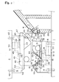
- Fig. 1 is a front elevational view showing a cross section of a part of the present double acting cam die in a state of a top dead center
- Fig. 2 is a front elevational view showing a cross section of a part of the present double acting cam die in a state of a bottom dead center
- Fig. 3 is a perspective view of the present double acting cam die in the state of the bottom dead center.
- a lower die main body 1 is provided with a slide cam base 2, a slide cam 3 which is guided by the slide cam base 2 and has a first processing member such as a punch or the like mounted thereto, an energizing body which is interposed between the slide cam base 2 and the slide cam 3 so as to energize the slide cam 3, and a supporting member 7.
- An upper die main body 4 is provided with an actuating cam 5 which is brought into contact with the slide cam base 2 and the slide cam 3 so as to drive the slide cam 3, and has a second processing member such as a punch or the like mounted thereto, a guiding member 6 which guides the actuating cam 5, and an energizing body which is interposed between the guiding member 6 and the actuating cam 5 so as to energize the actuating cam 5.
- a second processing member such as a punch or the like mounted thereto
- a guiding member 6 which guides the actuating cam 5
- an energizing body which is interposed between the guiding member 6 and the actuating cam 5 so as to energize the actuating cam 5.
- Reference symbol W denotes a work.
- the slide cam base 2 is firmly fixed to the lower die main body 1 by bolts 8.
- Wear plates 10 structuring sliding surfaces, formed in an inward downward slope and having a trapezoidal cross section are firmly fixed to both side bottom portions of a groove 9 guiding the slide cam 3 of the slide cam base 2.
- the slide cam 3 is structured such that a protruding piece 11 having a rectangular cross section is protruded to a lower side, sliding surfaces are structured in both sides of the protruding piece 11, and wear plates 12 formed in an outward upward slope and having a trapezoidal cross section are firmly fixed to the both sides.
- the wear plates 12 slide on the wear plates 10.
- a side end portion of the wear plate 12 is protruded to an outer side from a side surface of the slide cam 3, a lower surface of the guide plate 13 is brought into contact with an upper surface of an outward protruding portion of the wear plate 12, and the guide plate 13 is firmly fixed to the slide cam base 2 by bolts 14.
- the slide cam 3 slides on the slide cam base 2 in the manner mentioned above. Further, the wear plate 10 having the inward downward slope is firmly fixed to the slide cam base 2, and the wear plate 12 having the outward upward slope and sliding on the wear plate 10 is firmly fixed to the slide cam 3. Accordingly, the slide cam 3 is urged to a center side and accurately slides.
- a bracket 15 is firmly fixed to a bottom surface of the slide cam 3 by a bolt 16, and a leading end of a rod 18 of a gas spring 17 having a base end firmly fixed to the slide cam base 2 is brought into contact with the bracket 15.
- the rod 18 of the gas spring 17 is contracted, however, in accordance with an upward movement of the actuating cam 5, the rod 18 of the gas spring 17 is gradually extended, whereby the slide cam 3 is not brought into contact with the cam slope surface 19 of the slide cam base 2 and the cam slope surface 20 of the slide cam 3.
- the rod 18 of the gas spring 17 is extended so as to bring a rear end surface 21 of the slide cam 3 into contact with a stop surface 22 of the slide cam base 2. Accordingly, the slide cam 3 stops.
- the gas spring 17 is structured such that a high pressure gas in correspondence to an intended use, for example, a high pressure gas of 150 kgf/cm 2 is received within a cylinder 23, and an approximately uniform output, for example, 150 kgf/cm 2 can be obtained all the length of a rod contraction stroke even in the case that the rod 18 protruding from the cylinder 23 is expanded and contracted.
- Two tanks are installed within the cylinder 23, however, when the rod 18 is contracted and the pressure is applied to one tank, the high pressure gas flows out from one tank so as to flow into another tank, whereby the approximately uniform output (the output may be slightly increased due to compression) can be obtained all the stroke of the rod 18.
- the high output can be obtained all the stroke from the operation start as is different from the coil spring, whereby it is possible to securely return the slide cam 3 and a safety operation can be achieved.
- a wear plate 24 is firmly fixed to the slide cam base 2 by a bolt 25
- a wear plate 26 is firmly fixed to the slide cam 3 by a bolt 27.
- the work W is mounted on the supporting member 7 which is fixed to the lower die main body 1 by a bolt 28.
- a first hole 29 and a second hole 30 are pierced on the work W.
- An angle ⁇ 1 of incline for processing a first processing member is 0 degree, and an angle ⁇ 2 of incline for processing a second processing member is 50 degree.
- the first hole 29 is formed on a vertical surface of the work W.
- Both the first processing member and the second processing member are exemplified by the piercing in the present embodiment, however, the present invention is not limited to this, and includes a notching, a forming and the other processing.
- angle ⁇ 1 of incline for processing the first processing member is 0 means that a first processing member mounting surface 31 of the slide cam 3 is a vertical surface.
- a punch plate 33 holding a punch 32 is firmly fixed to the first processing member mounting surface 31 by a bolt 34 in such a manner as to rise up while opposing to the first hole 29.
- the first hole 29 forms a hole by the punch 32 and a die bush 35 buried in the supporting member 7.
- the actuating cam 5 has a slope surface 36 which is brought into contact with the cam slope surface 19 of the slide cam base 2, and a slope surface 37 which is brought into contact with the cam slope surface 20 of the slide cam 3.
- the actuating cam 5 has a second working member mounting surface 38 in addition to the slope surfaces 36 and 37.
- the angle ⁇ 2 of incline for processing the second processing member is 50 degree, and in order to pierce the second hole 30 of the work W, a punch 39 is raised up by a punch holder 40 so as to be orthogonal to the second hole 30, and the punch holder 40 is firmly fixed to the second working member mounting surface 38 by a bolt 41.
- An angle of incline of the cam slope surface of the slide cam base 2 is set to 50 degree which is equal to the angle ⁇ 2 of incline for processing the second processing member such that the punch 39 moves in a direction of processing the second member having the angle ⁇ 2 of incline for processing the second member.
- the guide member 6 for guiding the actuating cam 5 is firmly fixed to the upper die main body 4 by a bolt 42.
- a groove 43 for guiding the actuating cam 5 of the guiding member 6 is provided, the upper portion of the actuating cam 5 is inserted into the groove 43, and a suspended piece 47 is protruded to an upper side portion of the actuating cam 5 so as to be slidably hanged down to a supporting piece 44 of the guiding member 6.
- a wear plate 45 is firmly fixed to an upper surface of the guiding member 6 by a bolt 46.
- a bracket 48 is firmly fixed to an upper surface of the actuating cam 5 by a bolt 49, and a leading end of a rod 51 of a gas spring 50 having a base end firmly fixed to the guiding member 6 is brought into contact with the bracket 48.
- the rod 51 of the gas spring 50 is contracted, however, in accordance with an upward movement of the actuating cam 5, the rod 51 of the gas spring 50 is gradually extended, whereby the slide cam 3 is not brought into contact with the cam slope surface 19 of the slide cam base 2 and the cam slope surface 20 of the slide cam 3.
- the rod 51 of the gas spring 50 is extended so as to bring a rear end surface 52 of the actuating cam 5 into contact with a stop surface 53 of the guiding member 6. Accordingly, the actuating cam 5 stops.
- the angle ⁇ 1 of incline for processing the first processing member includes 0 degree, 10 degree, 20 degree and the like
- the angle ⁇ 2 of incline for processing the second processing member includes 40 degree, 50 degree, 60 degree, 70 degree, 80 degree and the like.
- Various combinations between the angle ⁇ 1 of incline for processing the first processing member and the angle ⁇ 2 of incline for processing the second processing member can be considered.
- Setting the angle ⁇ 1 of incline for processing the first processing member to 0 degree, 10 degree and 20 degree means arranging the first processing member mounting surface 31 so as to correspond to the angle ⁇ 1 of incline of 0 degree, 10 degree and 20 degree.
- the second processing member mounting surface 38 so as to correspond to the angle ⁇ 2 of incline of 40 degree, 50 degree, 60 degree, 70 degree and 80 degree.
- ⁇ 2 50 degree corresponds to an illustrated state
- ⁇ 2 40 degree, 50 degree, 60 degree, 70 degree and 80 degree requires reshaping a new actuating cam 3. It is necessary to change the slide cam base 2 in correspondence to the angle ⁇ 2 of incline.
- a hatched replacement member 54 of the slide cam base 2 is structured so as to be replaceable. The replacement member 54 in which the cam slope surface 19 matches to the angle ⁇ 2 is used.
- the required member can be processed by four members comprising the guiding member in addition to the slide cam base, the slide cam and the actuating cam.
- the number of the members can be reduced and a cost reduction can be achieved.
- the present invention can be applied to a notching process, a bending process, a forming process and the other press dying process in addition to the piercing in the different processing directions.
- the present invention provides the double acting cam die comprising the slide cam base, the slide cam which is guided by the slide cam base and has the first processing member such as the punch or the like mounted thereto, the energizing body which is interposed between the slide cam base and the slide cam so as to energize the slide cam, the actuating cam which is brought into contact with the slide cam base and the slide cam so as to drive the slide cam, and has the second processing member such as the punch or the like mounted thereto, the guiding member which guides the actuating cam, and the energizing body which is interposed between the guiding member and the actuating cam so as to energize the actuating cam, it is possible to process in the same step even in the case that the processing directions are different, it is possible to reduce the number of the constituting parts of the die required for all the steps of the press dying, the design can be easily executed, and it is possible to easily correspond to the design change.
- the actuating cam is hanged by the guiding member and is slidably provided.
- the wear plate is provided in each of the sliding surfaces between the slide cam and the slide cam base.
- the wear plate is interposed in the sliding surface between the slide cam and the guiding member.
- the energizing body is constituted by the gas spring.
Landscapes
- Engineering & Computer Science (AREA)
- Mechanical Engineering (AREA)
- Mounting, Exchange, And Manufacturing Of Dies (AREA)
- Punching Or Piercing (AREA)
Applications Claiming Priority (2)
| Application Number | Priority Date | Filing Date | Title |
|---|---|---|---|
| JP2003384825 | 2003-11-14 | ||
| JP2003384825A JP2005144493A (ja) | 2003-11-14 | 2003-11-14 | 複動カム型 |
Publications (2)
| Publication Number | Publication Date |
|---|---|
| EP1531015A1 true EP1531015A1 (fr) | 2005-05-18 |
| EP1531015B1 EP1531015B1 (fr) | 2006-06-07 |
Family
ID=34431492
Family Applications (1)
| Application Number | Title | Priority Date | Filing Date |
|---|---|---|---|
| EP20040015328 Expired - Lifetime EP1531015B1 (fr) | 2003-11-14 | 2004-06-30 | Outil de presse à double action à came |
Country Status (6)
| Country | Link |
|---|---|
| US (1) | US7111538B2 (fr) |
| EP (1) | EP1531015B1 (fr) |
| JP (1) | JP2005144493A (fr) |
| CA (1) | CA2480746A1 (fr) |
| DE (1) | DE602004001117T2 (fr) |
| ES (1) | ES2265128T3 (fr) |
Cited By (3)
| Publication number | Priority date | Publication date | Assignee | Title |
|---|---|---|---|---|
| DE102006050530A1 (de) * | 2006-10-26 | 2008-04-30 | Wilhelm Karmann Gmbh | Presswerkzeug zur Bearbeitung eines Werkstücks |
| FR3043345A1 (fr) * | 2015-11-06 | 2017-05-12 | Peugeot Citroen Automobiles Sa | Outillage permettant la decoupe d’une piece de tole comprenant deux coulisseaux superposes et procede de decoupe au moyen d’un tel outillage |
| FR3053613A1 (fr) * | 2016-07-06 | 2018-01-12 | Peugeot Citroen Automobiles Sa | Outil de formage d’un flan de tole qui comporte des moyens de poinconnage suivant deux directions distinctes |
Families Citing this family (5)
| Publication number | Priority date | Publication date | Assignee | Title |
|---|---|---|---|---|
| KR101095056B1 (ko) | 2009-04-07 | 2011-12-19 | (주)신영하이테크 | 멀티 캠 유닛 |
| US10406584B2 (en) * | 2014-06-27 | 2019-09-10 | Honda Motor Co., Ltd. | Methods and apparatus to shape a workpiece |
| CN105149418B (zh) * | 2015-07-31 | 2017-03-08 | 苏州飞华铝制工业有限公司 | 一种多角度冲孔结构 |
| CN107737833A (zh) * | 2017-11-30 | 2018-02-27 | 重庆安亚模具制造有限公司 | 一种多角度孔冲压模具的上模 |
| KR102923039B1 (ko) * | 2020-07-02 | 2026-02-04 | 현대자동차 주식회사 | 다 방향 멀티 캠 방식의 프레스 장치 |
Citations (3)
| Publication number | Priority date | Publication date | Assignee | Title |
|---|---|---|---|---|
| JPS617024A (ja) * | 1985-06-08 | 1986-01-13 | Takatsu Seisakusho:Kk | 自動車のフロントピラー等の製造方法およびその装置 |
| EP0557551A1 (fr) * | 1992-02-26 | 1993-09-01 | UMIX Co., Ltd. | Matrice avec structure triple à glissières |
| EP1238721A2 (fr) * | 2001-03-05 | 2002-09-11 | Umix Co., Ltd. | Outillage de formage pour pliage angulaire négatif |
Family Cites Families (6)
| Publication number | Priority date | Publication date | Assignee | Title |
|---|---|---|---|---|
| GB1422950A (en) * | 1972-05-31 | 1976-01-28 | Harris R E | Apparatus for shearing sheet material |
| IT1190865B (it) * | 1982-06-09 | 1988-02-24 | Salvagnini Transferica Spa | Cesoia per lamiera con lame a squadra a segmenti reciprocamente spostabili |
| ES2069654T3 (es) * | 1990-11-09 | 1995-05-16 | Umix Co Ltd | Matriz con leva deslizante. |
| JP2880490B1 (ja) * | 1997-11-14 | 1999-04-12 | ユミックス株式会社 | プレス装置 |
| DE19855919A1 (de) * | 1998-12-03 | 2000-06-08 | Umix Co Ltd | Preßvorrichtung |
| EP1172185A1 (fr) * | 2000-07-14 | 2002-01-16 | Adolf Mohr Maschinenfabrik GmbH & Co. KG | Dispositif pour la coupe de matériaux en feuille |
-
2003
- 2003-11-14 JP JP2003384825A patent/JP2005144493A/ja active Pending
-
2004
- 2004-06-30 EP EP20040015328 patent/EP1531015B1/fr not_active Expired - Lifetime
- 2004-06-30 DE DE200460001117 patent/DE602004001117T2/de not_active Expired - Fee Related
- 2004-06-30 ES ES04015328T patent/ES2265128T3/es not_active Expired - Lifetime
- 2004-07-08 US US10/885,646 patent/US7111538B2/en not_active Expired - Fee Related
- 2004-09-07 CA CA 2480746 patent/CA2480746A1/fr not_active Abandoned
Patent Citations (3)
| Publication number | Priority date | Publication date | Assignee | Title |
|---|---|---|---|---|
| JPS617024A (ja) * | 1985-06-08 | 1986-01-13 | Takatsu Seisakusho:Kk | 自動車のフロントピラー等の製造方法およびその装置 |
| EP0557551A1 (fr) * | 1992-02-26 | 1993-09-01 | UMIX Co., Ltd. | Matrice avec structure triple à glissières |
| EP1238721A2 (fr) * | 2001-03-05 | 2002-09-11 | Umix Co., Ltd. | Outillage de formage pour pliage angulaire négatif |
Non-Patent Citations (1)
| Title |
|---|
| PATENT ABSTRACTS OF JAPAN vol. 010, no. 153 (M - 484) 3 June 1986 (1986-06-03) * |
Cited By (3)
| Publication number | Priority date | Publication date | Assignee | Title |
|---|---|---|---|---|
| DE102006050530A1 (de) * | 2006-10-26 | 2008-04-30 | Wilhelm Karmann Gmbh | Presswerkzeug zur Bearbeitung eines Werkstücks |
| FR3043345A1 (fr) * | 2015-11-06 | 2017-05-12 | Peugeot Citroen Automobiles Sa | Outillage permettant la decoupe d’une piece de tole comprenant deux coulisseaux superposes et procede de decoupe au moyen d’un tel outillage |
| FR3053613A1 (fr) * | 2016-07-06 | 2018-01-12 | Peugeot Citroen Automobiles Sa | Outil de formage d’un flan de tole qui comporte des moyens de poinconnage suivant deux directions distinctes |
Also Published As
| Publication number | Publication date |
|---|---|
| US7111538B2 (en) | 2006-09-26 |
| ES2265128T3 (es) | 2007-02-01 |
| DE602004001117T2 (de) | 2007-01-04 |
| US20050103177A1 (en) | 2005-05-19 |
| JP2005144493A (ja) | 2005-06-09 |
| EP1531015B1 (fr) | 2006-06-07 |
| DE602004001117D1 (de) | 2006-07-20 |
| CA2480746A1 (fr) | 2005-05-14 |
Similar Documents
| Publication | Publication Date | Title |
|---|---|---|
| US7434443B2 (en) | Compound press-forming apparatus and compound press-forming method | |
| US5711180A (en) | Pressing cam die | |
| US5598635A (en) | Hydraulic puncher | |
| US4510789A (en) | Press brake | |
| JP2000233239A (ja) | 複合加工プレス型 | |
| EP1238721A2 (fr) | Outillage de formage pour pliage angulaire négatif | |
| EP1531015B1 (fr) | Outil de presse à double action à came | |
| US6220137B1 (en) | Press apparatus | |
| US11253902B2 (en) | Hemming apparatus | |
| US4082026A (en) | Portable press | |
| US6993952B2 (en) | Multipurpose horizontal press having a fixed workpiece-holder for a tubular workpiece to be drawn or tapered | |
| CN104707908A (zh) | 一种翻孔模具 | |
| CN210648102U (zh) | 一种冲压模具及冲压设备 | |
| KR101566902B1 (ko) | C-형강류 다공 자동 가공기 | |
| US4392400A (en) | Trimming and piercing apparatus | |
| CN112238184A (zh) | 一种管夹冲压模具 | |
| CN213645751U (zh) | 一种用于锻造金属器件的液压锻造装置 | |
| US5440912A (en) | Form and punch apparatus | |
| KR101272545B1 (ko) | 플랜지 음각 가공을 위한 프레스의 캠 구동장치 각도 조절 장치 | |
| JP2003230921A (ja) | 複合加工プレス型 | |
| JP2004122231A (ja) | 複合プレス成形装置及び複合プレス成形方法 | |
| JP2003326326A (ja) | プレス装置 | |
| CN217121449U (zh) | 一种背门内板模具 | |
| KR101562358B1 (ko) | 프레스의 경사캠 장치 | |
| US6467144B1 (en) | Multifunction insert press |
Legal Events
| Date | Code | Title | Description |
|---|---|---|---|
| PUAI | Public reference made under article 153(3) epc to a published international application that has entered the european phase |
Free format text: ORIGINAL CODE: 0009012 |
|
| AK | Designated contracting states |
Kind code of ref document: A1 Designated state(s): AT BE BG CH CY CZ DE DK EE ES FI FR GB GR HU IE IT LI LU MC NL PL PT RO SE SI SK TR |
|
| AX | Request for extension of the european patent |
Extension state: AL HR LT LV MK |
|
| 17P | Request for examination filed |
Effective date: 20050405 |
|
| GRAP | Despatch of communication of intention to grant a patent |
Free format text: ORIGINAL CODE: EPIDOSNIGR1 |
|
| AKX | Designation fees paid |
Designated state(s): DE ES FR GB IT SE |
|
| GRAS | Grant fee paid |
Free format text: ORIGINAL CODE: EPIDOSNIGR3 |
|
| GRAA | (expected) grant |
Free format text: ORIGINAL CODE: 0009210 |
|
| AK | Designated contracting states |
Kind code of ref document: B1 Designated state(s): DE ES FR GB IT SE |
|
| REG | Reference to a national code |
Ref country code: GB Ref legal event code: FG4D |
|
| REF | Corresponds to: |
Ref document number: 602004001117 Country of ref document: DE Date of ref document: 20060720 Kind code of ref document: P |
|
| REG | Reference to a national code |
Ref country code: SE Ref legal event code: TRGR |
|
| ET | Fr: translation filed | ||
| REG | Reference to a national code |
Ref country code: ES Ref legal event code: FG2A Ref document number: 2265128 Country of ref document: ES Kind code of ref document: T3 |
|
| PLBE | No opposition filed within time limit |
Free format text: ORIGINAL CODE: 0009261 |
|
| STAA | Information on the status of an ep patent application or granted ep patent |
Free format text: STATUS: NO OPPOSITION FILED WITHIN TIME LIMIT |
|
| 26N | No opposition filed |
Effective date: 20070308 |
|
| PGFP | Annual fee paid to national office [announced via postgrant information from national office to epo] |
Ref country code: ES Payment date: 20070620 Year of fee payment: 4 |
|
| PGFP | Annual fee paid to national office [announced via postgrant information from national office to epo] |
Ref country code: SE Payment date: 20070626 Year of fee payment: 4 |
|
| PGFP | Annual fee paid to national office [announced via postgrant information from national office to epo] |
Ref country code: DE Payment date: 20070830 Year of fee payment: 4 |
|
| PGFP | Annual fee paid to national office [announced via postgrant information from national office to epo] |
Ref country code: FR Payment date: 20070619 Year of fee payment: 4 |
|
| GBPC | Gb: european patent ceased through non-payment of renewal fee |
Effective date: 20080630 |
|
| EUG | Se: european patent has lapsed | ||
| REG | Reference to a national code |
Ref country code: FR Ref legal event code: ST Effective date: 20090228 |
|
| PG25 | Lapsed in a contracting state [announced via postgrant information from national office to epo] |
Ref country code: DE Free format text: LAPSE BECAUSE OF NON-PAYMENT OF DUE FEES Effective date: 20090101 |
|
| PG25 | Lapsed in a contracting state [announced via postgrant information from national office to epo] |
Ref country code: GB Free format text: LAPSE BECAUSE OF NON-PAYMENT OF DUE FEES Effective date: 20080630 |
|
| REG | Reference to a national code |
Ref country code: ES Ref legal event code: FD2A Effective date: 20080701 |
|
| PG25 | Lapsed in a contracting state [announced via postgrant information from national office to epo] |
Ref country code: FR Free format text: LAPSE BECAUSE OF NON-PAYMENT OF DUE FEES Effective date: 20080630 Ref country code: IT Free format text: LAPSE BECAUSE OF NON-PAYMENT OF DUE FEES Effective date: 20080630 |
|
| PG25 | Lapsed in a contracting state [announced via postgrant information from national office to epo] |
Ref country code: ES Free format text: LAPSE BECAUSE OF NON-PAYMENT OF DUE FEES Effective date: 20080701 |
|
| PGFP | Annual fee paid to national office [announced via postgrant information from national office to epo] |
Ref country code: IT Payment date: 20070630 Year of fee payment: 4 |
|
| PG25 | Lapsed in a contracting state [announced via postgrant information from national office to epo] |
Ref country code: SE Free format text: LAPSE BECAUSE OF NON-PAYMENT OF DUE FEES Effective date: 20080701 |