EP1531364A2 - Lithographisches Gerät und Verfahren zur Herstellung einer Vorrichtung - Google Patents
Lithographisches Gerät und Verfahren zur Herstellung einer Vorrichtung Download PDFInfo
- Publication number
- EP1531364A2 EP1531364A2 EP04078004A EP04078004A EP1531364A2 EP 1531364 A2 EP1531364 A2 EP 1531364A2 EP 04078004 A EP04078004 A EP 04078004A EP 04078004 A EP04078004 A EP 04078004A EP 1531364 A2 EP1531364 A2 EP 1531364A2
- Authority
- EP
- European Patent Office
- Prior art keywords
- reference frame
- lithographic apparatus
- temperature
- substrate
- projection
- Prior art date
- Legal status (The legal status is an assumption and is not a legal conclusion. Google has not performed a legal analysis and makes no representation as to the accuracy of the status listed.)
- Granted
Links
- 238000004519 manufacturing process Methods 0.000 title claims description 12
- 239000000758 substrate Substances 0.000 claims abstract description 73
- 239000000463 material Substances 0.000 claims abstract description 48
- 230000003750 conditioning effect Effects 0.000 claims description 35
- 230000005855 radiation Effects 0.000 claims description 23
- 238000000059 patterning Methods 0.000 claims description 19
- 230000001105 regulatory effect Effects 0.000 claims description 18
- 230000007613 environmental effect Effects 0.000 claims description 16
- 238000002955 isolation Methods 0.000 claims description 16
- 239000004411 aluminium Substances 0.000 claims description 15
- 229910052782 aluminium Inorganic materials 0.000 claims description 15
- XAGFODPZIPBFFR-UHFFFAOYSA-N aluminium Chemical compound [Al] XAGFODPZIPBFFR-UHFFFAOYSA-N 0.000 claims description 15
- 230000007774 longterm Effects 0.000 claims description 13
- 230000001276 controlling effect Effects 0.000 claims description 11
- 239000012530 fluid Substances 0.000 claims description 10
- XEEYBQQBJWHFJM-UHFFFAOYSA-N Iron Chemical compound [Fe] XEEYBQQBJWHFJM-UHFFFAOYSA-N 0.000 claims description 9
- 229910000838 Al alloy Inorganic materials 0.000 claims description 8
- 239000007787 solid Substances 0.000 claims description 8
- PXHVJJICTQNCMI-UHFFFAOYSA-N Nickel Chemical compound [Ni] PXHVJJICTQNCMI-UHFFFAOYSA-N 0.000 claims description 6
- 238000005286 illumination Methods 0.000 claims description 6
- 239000011248 coating agent Substances 0.000 claims description 5
- 238000000576 coating method Methods 0.000 claims description 5
- 229910001220 stainless steel Inorganic materials 0.000 claims description 5
- 239000010935 stainless steel Substances 0.000 claims description 5
- 229910001018 Cast iron Inorganic materials 0.000 claims description 4
- RYGMFSIKBFXOCR-UHFFFAOYSA-N Copper Chemical compound [Cu] RYGMFSIKBFXOCR-UHFFFAOYSA-N 0.000 claims description 4
- 229910000831 Steel Inorganic materials 0.000 claims description 4
- 229910010293 ceramic material Inorganic materials 0.000 claims description 4
- 229910052802 copper Inorganic materials 0.000 claims description 4
- 239000010949 copper Substances 0.000 claims description 4
- 239000010438 granite Substances 0.000 claims description 4
- 229910052742 iron Inorganic materials 0.000 claims description 4
- 229910052573 porcelain Inorganic materials 0.000 claims description 4
- 239000010959 steel Substances 0.000 claims description 4
- RTAQQCXQSZGOHL-UHFFFAOYSA-N Titanium Chemical compound [Ti] RTAQQCXQSZGOHL-UHFFFAOYSA-N 0.000 claims description 3
- 239000002131 composite material Substances 0.000 claims description 3
- 239000004567 concrete Substances 0.000 claims description 3
- 229910052759 nickel Inorganic materials 0.000 claims description 3
- 239000010936 titanium Substances 0.000 claims description 3
- 229910052719 titanium Inorganic materials 0.000 claims description 3
- 230000032258 transport Effects 0.000 claims description 3
- 230000001419 dependent effect Effects 0.000 claims description 2
- 229910052751 metal Inorganic materials 0.000 claims 1
- 239000002184 metal Substances 0.000 claims 1
- 238000001816 cooling Methods 0.000 description 17
- 230000003287 optical effect Effects 0.000 description 9
- XLYOFNOQVPJJNP-UHFFFAOYSA-N water Substances O XLYOFNOQVPJJNP-UHFFFAOYSA-N 0.000 description 9
- 238000005259 measurement Methods 0.000 description 7
- 229910001374 Invar Inorganic materials 0.000 description 6
- 239000010410 layer Substances 0.000 description 5
- 239000000956 alloy Substances 0.000 description 4
- 230000008901 benefit Effects 0.000 description 4
- 230000001143 conditioned effect Effects 0.000 description 4
- 238000003384 imaging method Methods 0.000 description 4
- 229910045601 alloy Inorganic materials 0.000 description 3
- 238000013461 design Methods 0.000 description 3
- 238000009826 distribution Methods 0.000 description 3
- 230000000694 effects Effects 0.000 description 3
- 230000006870 function Effects 0.000 description 3
- 238000007654 immersion Methods 0.000 description 3
- 239000005022 packaging material Substances 0.000 description 3
- 238000011084 recovery Methods 0.000 description 3
- 239000000110 cooling liquid Substances 0.000 description 2
- 239000000498 cooling water Substances 0.000 description 2
- 238000009434 installation Methods 0.000 description 2
- 239000007788 liquid Substances 0.000 description 2
- 238000001459 lithography Methods 0.000 description 2
- 238000003754 machining Methods 0.000 description 2
- 238000012423 maintenance Methods 0.000 description 2
- 239000007769 metal material Substances 0.000 description 2
- 238000000034 method Methods 0.000 description 2
- 230000010363 phase shift Effects 0.000 description 2
- 230000003068 static effect Effects 0.000 description 2
- 238000003466 welding Methods 0.000 description 2
- XUIMIQQOPSSXEZ-UHFFFAOYSA-N Silicon Chemical compound [Si] XUIMIQQOPSSXEZ-UHFFFAOYSA-N 0.000 description 1
- 230000009471 action Effects 0.000 description 1
- 238000003491 array Methods 0.000 description 1
- 230000002238 attenuated effect Effects 0.000 description 1
- 238000005266 casting Methods 0.000 description 1
- 238000010276 construction Methods 0.000 description 1
- 239000004035 construction material Substances 0.000 description 1
- 238000011109 contamination Methods 0.000 description 1
- 239000012809 cooling fluid Substances 0.000 description 1
- 238000012937 correction Methods 0.000 description 1
- 238000001514 detection method Methods 0.000 description 1
- 238000011161 development Methods 0.000 description 1
- 230000009977 dual effect Effects 0.000 description 1
- 230000005670 electromagnetic radiation Effects 0.000 description 1
- 238000010894 electron beam technology Methods 0.000 description 1
- 230000005484 gravity Effects 0.000 description 1
- 238000010438 heat treatment Methods 0.000 description 1
- 238000007689 inspection Methods 0.000 description 1
- 230000010354 integration Effects 0.000 description 1
- 238000010884 ion-beam technique Methods 0.000 description 1
- 239000002346 layers by function Substances 0.000 description 1
- 239000004973 liquid crystal related substance Substances 0.000 description 1
- 230000005381 magnetic domain Effects 0.000 description 1
- 239000011159 matrix material Substances 0.000 description 1
- 230000015654 memory Effects 0.000 description 1
- QSHDDOUJBYECFT-UHFFFAOYSA-N mercury Chemical compound [Hg] QSHDDOUJBYECFT-UHFFFAOYSA-N 0.000 description 1
- 229910052753 mercury Inorganic materials 0.000 description 1
- 239000002245 particle Substances 0.000 description 1
- 238000005498 polishing Methods 0.000 description 1
- 238000012545 processing Methods 0.000 description 1
- 210000001747 pupil Anatomy 0.000 description 1
- 230000009467 reduction Effects 0.000 description 1
- 238000007493 shaping process Methods 0.000 description 1
- 229910052710 silicon Inorganic materials 0.000 description 1
- 239000010703 silicon Substances 0.000 description 1
- 230000006641 stabilisation Effects 0.000 description 1
- 238000011105 stabilization Methods 0.000 description 1
- 238000003860 storage Methods 0.000 description 1
- 230000002277 temperature effect Effects 0.000 description 1
- 239000010409 thin film Substances 0.000 description 1
- 238000011144 upstream manufacturing Methods 0.000 description 1
Images



Classifications
-
- G—PHYSICS
- G03—PHOTOGRAPHY; CINEMATOGRAPHY; ANALOGOUS TECHNIQUES USING WAVES OTHER THAN OPTICAL WAVES; ELECTROGRAPHY; HOLOGRAPHY
- G03F—PHOTOMECHANICAL PRODUCTION OF TEXTURED OR PATTERNED SURFACES, e.g. FOR PRINTING, FOR PROCESSING OF SEMICONDUCTOR DEVICES; MATERIALS THEREFOR; ORIGINALS THEREFOR; APPARATUS SPECIALLY ADAPTED THEREFOR
- G03F7/00—Photomechanical, e.g. photolithographic, production of textured or patterned surfaces, e.g. printing surfaces; Materials therefor, e.g. comprising photoresists; Apparatus specially adapted therefor
- G03F7/70—Microphotolithographic exposure; Apparatus therefor
- G03F7/708—Construction of apparatus, e.g. environment aspects, hygiene aspects or materials
- G03F7/70808—Construction details, e.g. housing, load-lock, seals or windows for passing light in or out of apparatus
- G03F7/70825—Mounting of individual elements, e.g. mounts, holders or supports
-
- G—PHYSICS
- G02—OPTICS
- G02B—OPTICAL ELEMENTS, SYSTEMS OR APPARATUS
- G02B7/00—Mountings, adjusting means, or light-tight connections, for optical elements
- G02B7/02—Mountings, adjusting means, or light-tight connections, for optical elements for lenses
- G02B7/028—Mountings, adjusting means, or light-tight connections, for optical elements for lenses with means for compensating for changes in temperature or for controlling the temperature; thermal stabilisation
-
- G—PHYSICS
- G03—PHOTOGRAPHY; CINEMATOGRAPHY; ANALOGOUS TECHNIQUES USING WAVES OTHER THAN OPTICAL WAVES; ELECTROGRAPHY; HOLOGRAPHY
- G03F—PHOTOMECHANICAL PRODUCTION OF TEXTURED OR PATTERNED SURFACES, e.g. FOR PRINTING, FOR PROCESSING OF SEMICONDUCTOR DEVICES; MATERIALS THEREFOR; ORIGINALS THEREFOR; APPARATUS SPECIALLY ADAPTED THEREFOR
- G03F7/00—Photomechanical, e.g. photolithographic, production of textured or patterned surfaces, e.g. printing surfaces; Materials therefor, e.g. comprising photoresists; Apparatus specially adapted therefor
- G03F7/70—Microphotolithographic exposure; Apparatus therefor
- G03F7/708—Construction of apparatus, e.g. environment aspects, hygiene aspects or materials
- G03F7/70808—Construction details, e.g. housing, load-lock, seals or windows for passing light in or out of apparatus
- G03F7/70833—Mounting of optical systems, e.g. mounting of illumination system, projection system or stage systems on base-plate or ground
-
- G—PHYSICS
- G03—PHOTOGRAPHY; CINEMATOGRAPHY; ANALOGOUS TECHNIQUES USING WAVES OTHER THAN OPTICAL WAVES; ELECTROGRAPHY; HOLOGRAPHY
- G03F—PHOTOMECHANICAL PRODUCTION OF TEXTURED OR PATTERNED SURFACES, e.g. FOR PRINTING, FOR PROCESSING OF SEMICONDUCTOR DEVICES; MATERIALS THEREFOR; ORIGINALS THEREFOR; APPARATUS SPECIALLY ADAPTED THEREFOR
- G03F7/00—Photomechanical, e.g. photolithographic, production of textured or patterned surfaces, e.g. printing surfaces; Materials therefor, e.g. comprising photoresists; Apparatus specially adapted therefor
- G03F7/70—Microphotolithographic exposure; Apparatus therefor
- G03F7/708—Construction of apparatus, e.g. environment aspects, hygiene aspects or materials
- G03F7/70858—Environment aspects, e.g. pressure of beam-path gas, temperature
-
- G—PHYSICS
- G03—PHOTOGRAPHY; CINEMATOGRAPHY; ANALOGOUS TECHNIQUES USING WAVES OTHER THAN OPTICAL WAVES; ELECTROGRAPHY; HOLOGRAPHY
- G03F—PHOTOMECHANICAL PRODUCTION OF TEXTURED OR PATTERNED SURFACES, e.g. FOR PRINTING, FOR PROCESSING OF SEMICONDUCTOR DEVICES; MATERIALS THEREFOR; ORIGINALS THEREFOR; APPARATUS SPECIALLY ADAPTED THEREFOR
- G03F7/00—Photomechanical, e.g. photolithographic, production of textured or patterned surfaces, e.g. printing surfaces; Materials therefor, e.g. comprising photoresists; Apparatus specially adapted therefor
- G03F7/70—Microphotolithographic exposure; Apparatus therefor
- G03F7/708—Construction of apparatus, e.g. environment aspects, hygiene aspects or materials
- G03F7/70858—Environment aspects, e.g. pressure of beam-path gas, temperature
- G03F7/709—Vibration, e.g. vibration detection, compensation, suppression or isolation
-
- G—PHYSICS
- G03—PHOTOGRAPHY; CINEMATOGRAPHY; ANALOGOUS TECHNIQUES USING WAVES OTHER THAN OPTICAL WAVES; ELECTROGRAPHY; HOLOGRAPHY
- G03F—PHOTOMECHANICAL PRODUCTION OF TEXTURED OR PATTERNED SURFACES, e.g. FOR PRINTING, FOR PROCESSING OF SEMICONDUCTOR DEVICES; MATERIALS THEREFOR; ORIGINALS THEREFOR; APPARATUS SPECIALLY ADAPTED THEREFOR
- G03F7/00—Photomechanical, e.g. photolithographic, production of textured or patterned surfaces, e.g. printing surfaces; Materials therefor, e.g. comprising photoresists; Apparatus specially adapted therefor
- G03F7/70—Microphotolithographic exposure; Apparatus therefor
- G03F7/708—Construction of apparatus, e.g. environment aspects, hygiene aspects or materials
- G03F7/7095—Materials, e.g. materials for housing, stage or other support having particular properties, e.g. weight, strength, conductivity, thermal expansion coefficient
-
- G—PHYSICS
- G03—PHOTOGRAPHY; CINEMATOGRAPHY; ANALOGOUS TECHNIQUES USING WAVES OTHER THAN OPTICAL WAVES; ELECTROGRAPHY; HOLOGRAPHY
- G03F—PHOTOMECHANICAL PRODUCTION OF TEXTURED OR PATTERNED SURFACES, e.g. FOR PRINTING, FOR PROCESSING OF SEMICONDUCTOR DEVICES; MATERIALS THEREFOR; ORIGINALS THEREFOR; APPARATUS SPECIALLY ADAPTED THEREFOR
- G03F7/00—Photomechanical, e.g. photolithographic, production of textured or patterned surfaces, e.g. printing surfaces; Materials therefor, e.g. comprising photoresists; Apparatus specially adapted therefor
- G03F7/70—Microphotolithographic exposure; Apparatus therefor
- G03F7/708—Construction of apparatus, e.g. environment aspects, hygiene aspects or materials
- G03F7/70991—Connection with other apparatus, e.g. multiple exposure stations, particular arrangement of exposure apparatus and pre-exposure and/or post-exposure apparatus; Shared apparatus, e.g. having shared radiation source, shared mask or workpiece stage, shared base-plate; Utilities, e.g. cable, pipe or wireless arrangements for data, power, fluids or vacuum
Definitions
- a lithographic apparatus is a machine that applies a desired pattern onto a target portion of a substrate.
- Lithographic apparatus can be used, for example, in the manufacture of integrated circuits (ICs).
- a patterning means such as a mask, may be used to generate a circuit pattern corresponding to an individual layer of the IC, and this pattern can be imaged onto a target portion (e.g. comprising part of, one or several dies) on a substrate (e.g. a silicon wafer) that has a layer of radiation-sensitive material (resist).
- a single substrate will contain a network of adjacent target portions that are successively exposed.
- lithographic apparatus include so-called steppers, in which each target portion is irradiated by exposing an entire pattern onto the target portion in one go, and so-called scanners, in which each target portion is irradiated by scanning the pattern through the projection beam in a given direction (the "scanning"-direction) while synchronously scanning the substrate parallel or anti-parallel to this direction.
- Lithographic apparatuses comprise a reference frame, which may also be referred as a metrology frame in the art.
- the reference frame provides support for the projection system.
- the reference frame is isolated from disturbances caused by other components of the lithographic apparatus, such as the long and short stroke motors used to drive the reticle and wafer stages.
- Reference frames are conventionally made from materials having a low coefficient of thermal expansion, such as alloys including Invar. Until now, it has been assumed that such materials having a low coefficient of thermal expansion are required in order to meet the thermal demands of the reference frame. Unfortunately, these materials are expensive resulting in a high manufacture cost. Furthermore, such materials are in limited supply and have a limited manufacturability.
- US-A-6 529 264 discloses a frame for connecting parts of an optical system, comprising two barrels disposed on top of their own flange-connection to an assembly frame.
- the patent addresses the problem that movements between certain points of the optical axis that are relatively weakly connected result in imaging performance loss.
- this patent addresses the problem of reducing these movements in the frame
- the frame is made of materials including aluminium and stainless steel.
- the frame does not constitute a reference frame, but can be seen as part of a projection optics assembly, where it provides the function of improving the imaging performance of this assembly.
- a lithographic apparatus comprising:
- the present invention provides the additional surprising effect that the dynamic performance of the reference frame is equal or better than reference frames made of conventional materials, such as Invar.
- said reference frame supports a measuring system for determining certain dimensions of said substrate prior to its exposure and said projection system.
- said coefficient of thermal expansion is greater than approximately 2.9x10 -6 /K
- materials having a coefficient of thermal expansion greater than approximately 2.9x10 -6 /K provide a reference frame having sufficient mechanical and thermal stability.
- SiSiC having a coefficient of thermal expansion of approximately 2.9x10 -6 /K, is a material fulfilling these requirements.
- the reference frame comprises any one of the materials aluminium, aluminium alloy, titanium, iron, cast-iron, steel, stainless steel, copper, a ceramic material, concrete, granite, porcelain or combinations of these materials, for example, in a composite, sandwich or laminated structure.
- the production costs of the reference frame are reduced.
- an increase in design freedom is provided.
- the use of more versatile materials results in less technical production documentation with less mechanical development required for design changes in the reference frame and new frame designs.
- aluminium or aluminium alloy for example, are particularly dynamically robust.
- the reference frame comprises a solid block of material.
- a solid block provides a low internal thermal resistance and high thermal capacity. This results in only small temperature fluctuations from dynamic heat load variations and as a result small thermal drift of the reference frame.
- the solid block is machined to form said reference frame. By machining a solid block, time consuming and expensive welding procedures are avoided.
- the reference frame is provided with a thermal conditioning system for controlling the temperature of the projection system with respect to the reference frame.
- a thermal conditioning system for controlling the temperature of the projection system with respect to the reference frame.
- the reference frame is provided with a highly infrared reflective surface.
- the contamination risk is reduced, and/or the infrared reflection can be increased, and /or the friction coefficient can be enlarged.
- the surface may be provided in the form of a coating of a metal material of, for example, nickel.
- the reference frame is made of a material having a high specific heat and/or a high thermal conductivity. In particular, a material having a specific heat higher than about 600 J(kgK) and/or said thermal conductivity higher than about 20 W/(m K). By providing of reference frame of a material having a high specific heat and/or a high thermal conductivity, the thermal stability of the frame is improved.
- the reference frame is provided with a first temperature sensor for sensing a temperature of the reference frame.
- the projection system comprises a projection lens, wherein said projection lens is provided with a second temperature sensor for sensing a temperature of said projection lens.
- a further embodiment comprises a thermal conditioning system for thermally conditioning at least one of the reference frame and the projection system based on the temperatures sensed by at least one of the first and second temperature sensors. In this way both short and long term temperature fluctuations can be compensated for.
- the thermal conditioning system comprises a control circuit for controlling an amount of heat transported to or from at least one of the reference frame and projection lens, a temperature regulating element and a heat transporting system, wherein the temperature regulating element regulates the amount of heat transported by said heat transporting system, wherein the heat transporting system is in thermal contact with at least one of the reference frame and the projection lens, for transporting heat to or from the at least one of said reference frame and the projection lens, wherein the control circuit is arranged to be responsive to the temperature sensed by at least one of the first and second temperature sensors, the temperature regulating element is responsive to the control circuit and is in thermal contact with the heat transporting system, so that a set temperature is reached in at least one of the reference frame and the projection lens. In this way, the temperature control of at least one of the reference frame and projection lens is improved.
- control circuit is arranged to take the temperature sensed by the first temperature sensor into account in compensating for a short term environmental temperature fluctuation. In this way the thermal stability of the apparatus is improved.
- control circuit is arranged to take the temperature sensed by the second temperature sensor into account in compensating for a long term environmental temperature fluctuation. In this way the thermal stability of the apparatus is further improved.
- the thermal conditioning system comprises a single control loop for controlling the temperature of the reference frame and the projection lens. In this way both the long and short term environmental temperature fluctuations may be accounted for without adding significantly to the complexity and cost of the apparatus.
- the heat transporting system comprises a conditioning fluid which is heated or cooled to said set temperature.
- the thermal conditioning system provides a versatile and effective temperature control of the apparatus.
- lithographic apparatus in the manufacture of ICs, it should be understood that the lithographic apparatus described herein may have other applications, such as the manufacture of integrated optical systems, guidance and detection patterns for magnetic domain memories, liquid-crystal displays (LCDs), thin-film magnetic heads, etc.
- LCDs liquid-crystal displays
- any use of the terms “wafer” or “die” herein may be considered as synonymous with the more general terms “substrate” or "target portion”, respectively.
- the substrate referred to herein may be processed, before or after exposure, in for example a track (a tool that typically applies a layer of resist to a substrate and develops the exposed resist) or a metrology or inspection tool.
- the disclosure herein may be applied to such and other substrate processing tools.
- the substrate may be processed more than once, for example in order to create a multi-layer IC, so that the term substrate used herein may also refer to a substrate that already contains multiple processed layers.
- UV radiation e.g. having a wavelength of 365, 248, 193, 157 or 126 nm
- EUV extreme ultra-violet
- particle beams such as ion beams or electron beams.
- patterning means used herein should be broadly interpreted as referring to means that can be used to impart a projection beam with a pattern in its cross-section such as to create a pattern in a target portion of the substrate. It should be noted that the pattern imparted to the projection beam may not exactly correspond to the desired pattern in the target portion of the substrate. Generally, the pattern imparted to the projection beam will correspond to a particular functional layer in a device being created in the target portion, such as an integrated circuit.
- Patterning means may be transmissive or reflective.
- Examples of patterning means include masks, programmable mirror arrays, and programmable LCD panels.
- Masks are well known in lithography, and include mask types such as binary, alternating phase-shift, and attenuated phase-shift, as well as various hybrid mask types.
- An example of a programmable mirror array employs a matrix arrangement of small mirrors, each of which can be individually tilted so as to reflect an incoming radiation beam in different directions; in this manner, the reflected beam is patterned.
- the support structure may be a frame or table, for example, which may be fixed or movable as required and which may ensure that the patterning means is at a desired position, for example with respect to the projection system. Any use of the terms "reticle” or “mask” herein may be considered synonymous with the more general term "patterning means”.
- projection system used herein should be broadly interpreted as encompassing various types of projection system, including refractive optical systems, reflective optical systems, and catadioptric optical systems, as appropriate for example for the exposure radiation being used, or for other factors such as the use of an immersion fluid or the use of a vacuum. Any use of the term “lens” herein may be considered as synonymous with the more general term “projection system”.
- the illumination system may also encompass various types of optical components, including refractive, reflective, and catadioptric optical components for directing, shaping, or controlling the projection beam of radiation, and such components may also be referred to below, collectively or singularly, as a "lens”.
- the lithographic apparatus may be of a type having two (dual stage) or more substrate tables (and/or two or more mask tables). In such "multiple stage” machines the additional tables may be used in parallel, or preparatory steps may be carried out on one or more tables while one or more other tables are being used for exposure.
- the lithographic apparatus may also be of a type wherein the substrate is immersed in a liquid having a relatively high refractive index, e.g. water, so as to fill a space between the final element of the projection system and the substrate.
- Immersion liquids may also be applied to other spaces in the lithographic apparatus, for example, between the mask and the first element of the projection system. Immersion techniques are well known in the art for increasing the numerical aperture of projection systems.
- Figure 1 schematically depicts a lithographic apparatus according to a particular embodiment of the invention.
- the apparatus comprises:
- the apparatus is of a transmissive type (e.g. employing a transmissive mask).
- the apparatus may be of a reflective type (e.g. employing a programmable mirror array of a type as referred to above).
- the illuminator IL receives a beam of radiation from a radiation source SO.
- the source and the lithographic apparatus may be separate entities, for example when the source is an excimer laser. In such cases, the source is not considered to form part of the lithographic apparatus and the radiation beam is passed from the source SO to the illuminator IL with the aid of a beam delivery system BD comprising for example suitable directing mirrors and/or a beam expander. In other cases the source may be integral part of the apparatus, for example when the source is a mercury lamp.
- the source SO and the illuminator IL, together with the beam delivery system BD if required, may be referred to as a radiation system.
- the illuminator IL may comprise adjusting means AM for adjusting the angular intensity distribution of the beam.
- adjusting means AM for adjusting the angular intensity distribution of the beam.
- the illuminator IL generally comprises various other components, such as an integrator IN and a condenser CO.
- the illuminator provides a conditioned beam of radiation, referred to as the projection beam PB, having a desired uniformity and intensity distribution in its cross-section.
- the projection beam PB is incident on the mask MA, which is held on the mask table MT. Having traversed the mask MA, the projection beam PB passes through the lens PL, which focuses the beam onto a target portion C of the substrate W.
- the substrate table WT can be moved accurately, e.g. so as to position different target portions C in the path of the beam PB.
- the first positioning means PM and another position sensor can be used to accurately position the mask MA with respect to the path of the beam PB, e.g. after mechanical retrieval from a mask library, or during a scan.
- the mask table MT may be connected to a short stroke actuator only, or may be fixed.
- Mask MA and substrate W may be aligned using mask alignment marks M1, M2 and substrate alignment marks P1, P2.
- a reference frame MF which is also known as a so-called "metrology" frame
- a base frame BF provides a reference surface with respect to which the wafer is measured, and is mechanically isolated from the main apparatus structure.
- the reference frame MF is dynamically and thermally isolated.
- the reference frame MF is isolated from the base frame BF shown in Figure 1.
- the reference frame MF supports sensitive components such as the interferometer IF and other position sensors. Additionally, depending on the particular lithographic apparatus, the reference frame may also support the projections system PL. Further, the reference frame isolates those components supported thereon from vibration.
- the base frame BF Whilst the reference frame MF supports a metrology system, such as interferometer IF, and optionally also the projection system PL the base frame supports other components.
- the base frame BF supports a vibration isolation system VI for mechanically isolating the reference frame MF from the main apparatus structure.
- the base frame may support other components, such as the wafer stage WT (not shown in Figure 1) including the long stroke motor, and the reticle stage MT.
- the base frame BF is in contact with the fabrication floor, alternatively, it is not.
- the vibration isolation system VI may be realised for example, as airmounts or other equivalent systems, such as a magnetic system, a mechanical system comprising low stiffness mechanical beams, or a fluid based system, which provide a resilient support for the reference frame MF with a low elastic coefficient,
- the vibration isolation system is disposed between the base frame BF and the reference frame RF.
- the airmounts are suitable for use in a lithographic apparatus operating under a vacuum or atmospheric conditions.
- the reference frame MF may be realised for example as a heavy table.
- the reference frame MF is made of a material having a high coefficient of thermal expansion.
- Such materials may include, but are not limited to aluminium, aluminium alloy, titanium, iron, cast-iron, steel, stainless steel, copper, a ceramic material, concrete, granite, porcelain or combinations of these materials, for example, in a composite, sandwich or laminated structure.
- Table 1 shows some typical properties of some suitable construction materials are shown. Additionally, to aid comparision, values of the same properties are shown for Invar, which is a conventional material. It is further noted that aluminium alloys have a coefficient of thermal expansion typically in the region or around 23 to 24.5 x10 -6 /K.
- the reference frame MF is built up from a monolithic part, in other words a solid block. It may be cast or machined out of one block.
- a reference frame MF made in this way from aluminium, for example has approximately the same mass as a conventional reference frame.
- its integration into the lithographic apparatus, in particular, with respect to its interface with the vibration isolation system VI is very easily achieved.
- the temperature environment around the reference frame is stable, which leads to an expected 2 nanometres drift over minutes for 5 metres,., which matches the tolerances achieved by conventional reference frame materials, such as Invar, which have a much lower coefficient of thermal expansion than those materials considered according to the present invention.
- the dynamic performance of the reference frame made from materials which might be expected to exhibit poor dynamic performance due to their higher coefficient of thermal expansion, contrary to expectations exhibit a dynamic performance within those tolerances required in conventional lithographic apparatuses. Further, the centre of gravity can readily be adapted without sinificant influence on the dynamical performance.
- the reference frame MF is provided which is heavier than conventional reference frames. This is achieved, for example, by increasing its dimensions and/or by selecting a material, such as iron, which has a higher density. It has been found although such a heavier reference frame requires recalibration of the vibrational isolation system VI, it provides the further advantage that the dynamic performance of the reference frame MF is improved.
- aluminium alloy of the type AA5083 Al-4.4Mg-0.7Mn-0.15Cr. It is noted with respect to AA5083 or similar alloys, that it has the advantage that it has a very low internal stress level. This provides advantages in terms of machining a block of the material to form a reference frame MF and in terms of the long term stability of the reference frame.
- the specific heat is preferably higher than about 600 J(kgK) and/or the thermal conductivity is preferably higher than about 20 W/(m K).
- a cooling system may be incorporated either in or on the reference frame MF to improve the thermal stability.
- a fluid cooling system such as water or air cooling, may be used to cool the reference structure.
- the cooling system may be adapted in or on the reference frame to additionally cool the projection system.
- a cooling system provides long term stability and provides short recovery time after thermal drift (for example, as experience after service, maintenance, installation, etc.).
- Figure 2 depicts details of a lithographic apparatus according to a further embodiment of the invention.
- Figure 2 shows a reference frame MF which is suitable for use in a TwinScan lithographic apparatus.
- a TwinScan apparatus allows measurement at a measurement station 2 of one substrate W1 prior to exposure whilst exposure at an exposure station 4 of a different substrate W2 takes place.
- a first interferometer IF1 including a first Z-mirror ZM1 is provided to produce a "substrate map" of the substrate, that is the interferometer IF1 maps the contours of the substrates surface, so that in the exposure stage distortions in the surface of the substrate can be compensated for.
- a second interferometer IF2 including a second Z-mirror ZM2 ensures that the "substrate map" produced in the measurement stage for substrate W2 is faithfully reproduced.
- the reference frame MF supports both the metrology system IF and the projection system PL.
- the reference frame MF may comprise a first reference frame portion on which the components providing measuring functionality are mounted and a second reference frame portion on which the components providing the exposure measuring functionality are mounted. These two frame portions are then typically mounted, for example, by bolting either to each other or to an additional mounting frame.
- each frame portion may be provided with its own vibration isolation system, respectively.
- a single vibration isolation system may be provided.
- Figure 2 further shows an example of thermal conditioning system WC, for example, a cooling system, in particular a water cooling system WC which is formed in the reference frame MF.
- the reference frame MF is provided with ducts within the frame structure into which via inlets 6 a cooling liquid is introduced, and out of which via outlets 8 the cooling liquid leaves the structure.
- the ducts are formed so as to provide circulating cooling around that portion of the reference frame MF disposed opposite the measurement station 2 and exposure station 4, respectively.
- the cooling system includes one or more cooling circuits. In the particular embodiment shown in Figure 2, two cooling circuits are shown. In an alternative embodiment cooling may be provided by one cooling circuit. In a particular embodiment, a single cooling circuit may provide a cooling fluid to both the projection lens PL and the reference frame MF.
- the remaining components shown in Figure 2 correspond to those shown and described with respect to Figure 1 and are not described here further.
- Figure 3 depicts a top view of a reference frame isolated from a base frame according to an embodiment of the present invention showing certain components supported on the reference frame MF.
- Figure 3 shows more detail with respect to the isolated relationship between the reference frame MF and the base frame BF and shows in greater detail the reference frame Mf and those components mounted thereon.
- the reference frame MF comprises a first portion 3 and a second portion 5, wherein the first portion and the second portion are machined from first and second blocks respectively. Alternatively, they may be cast.
- the first and second portions 3,5 cooperate with one another to form the reference frame MF.
- the first portion serves to support inter alia those components for carrying out the measuring stage and the exposing stage.
- the second portion 5 supports the vibration isolation system VI, which serves to isolate the reference frame MF from the base frame BF. It is in the form of a bridge wherein bridge support portions 7, 8 are disposed on the first portion 3. A portion 10 extending the length of the bridge is supported by bridge support portions 7, 8. At opposite ends 9 of the extending portion 10 are vibration isolation system supporting portions 9.
- the airmounts AM which form the vibration isolation system VI in Figure 3 are disposed between portions 9 and the base frame BF. Via the bridge 5, the vibration isolation from the base frame BF afforded by the airmounts AM is transferred to the components mounted on the first portion 3.
- three airmounts are provided: one at either end of the bridge portion, a third (not shown in Figure 3, but shown in Figure 4), is disposed between the reference frame MF and the base frame BF at the opposite end in a longitudinal direction of the first portion of the reference frame MF.
- the invention is not however, limited in this respect, and it will be understood that the vibration isolation system VI may be realised in a number of alternative ways, with respect both to the nature of the system and the number and arrangement of the system components.
- the reference frame MF is comprises of a single portion, wherein the functionalities described above with respect to the first and second portion are combined into a single portion.
- the reference frame has a highly infrared reflective surface CO. This may be achieved by applying a coating to at least a part of the outer surface of the reference frame The coating covers the surface of the reference frame. It may cover at least the surface of a part of the reference frame MF.
- the coating is of a metal material such as nickel.
- a highly infrared reflective surface may be formed by polishing or surface treating the surface of the reference frame MF.
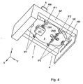
- Figure 4 depicts an underside view of the reference frame MF isolated from the base frame BF as shown in Figure 3.
- those components mounted on the underside of the reference frame are shown.
- These include the interferometers IF1 arranged to carry out functions at the measuring station 2 and the interferometers IF2 arranged to carry out functions at the exposing station 4.
- Associated with each of these interferometers IF1, IF2 are associated Z-mirrors ZM1, ZM2, respectively.
- Also shown at the measuring station 2 is a substrate chuck SC which serves to support a substrate W. Once the measuring stage has been carried out, the substrate chuck SC moves from an aligned position with the measuring station 2 to an aligned position with respect to the exposing station 4.
- FIG. 4 shows the vibrational isolation of the reference frame MF with respect to the base frame BF by virtue of a further airmount AM which is provided between part of the first portion 3 of the reference frame MF and the base frame BF. Also seen, is one of the airmounts AM mounted between the second portion 5 and the base frame BF.
- the temperature control of the projection lens PL, the reference frame MF, interferometers IF and other sensors is at the milliKelvin level and below.
- the temperature control is of the order of 0.1 mK/5 minutes. It is further desirable that the temperature stability of the environment of the projection lens PL, reference frame MF, interferometers IF and other sensors is in the order of 30 mK. It has been found that conventional lithographic apparatuses do not provide such temperature control.
- a temperature sensor is provided only on the projection system. Only such a lens sensor is used for determination of the temperature set point for the thermal conditioning system for the supply of water in a lens circuit water cabinet (LCWC) and a motor circuit water circuit (MCWC) and air in an air control cabinet (ACC). Due to the large time constant and because of the thermal isolation of the lens, it has been found that the lens is insensitive to environmental temperature fluctuations. On the other hand, the reference frame MF and other temperature critical components are much more sensitive. Therefore, by sensing the temperature of the reference frame MF as well as the projection lens, both long term and short term fluctuations can be detected and accounted for.
- LCWC lens circuit water cabinet
- MCWC motor circuit water circuit
- ACC air control cabinet
- a reference frame MF of a material such as aluminium, which has a high coefficient of thermal expansion may be thermally conditioned, for example, with a water conditioning system.
- the reference frame MF is conditioned with the same water that conditions the projection system, in particular, the projection lens. Since the aluminium reference frame MF is more sensitive to environmental temperature fluctuations than a conventional reference frame, to compensate for a short term environmental temperature fluctuation, for example, the effect of actuator or a cover opening and closing, the temperature of the reference frame MF is sensed, and the temperature sensed is preferably used in the temperature control algorithm for compensation of the short term environmental temperature fluctuations.
- the temperature of the projection system PL is sensed with a sensor, for example, disposed on the projection lens, the temperature sensed is preferably used in combination with the temperature of the reference frame in the control algorithm for compensation of the long term environmental temperature fluctuations. It is desired to control the long term temperature of the apparatus, because the temperature of, in particular, the projection system is preferably to be kept stable at an operating temperature. A typical operating temperature being around 22 degrees Celcius. It has been found that both the long and short term temperature fluctuations may be controlled in a single control loop, as described in more detail below.
- Figure 5 depicts details of a reference frame MF, a projection lens PL and a thermal conditioning system 20.
- the thermal stability of the lithographic apparatus is improved.
- the thermal stability of the frame is improved. Since a reference frame MF of aluminium is more sensitive to environmental temperature fluctuations than conventional reference frames made of invar.
- a control loop is used to regulate the temperature of at least one of the projection lens PL and the reference frame MF.
- at least one first temperature sensor 21 is provided for sensing a temperature of the reference frame MF.
- a further second temperature sensor 22 may be provided on the projection lens PL for sensing a temperature of the projection lens PL.
- the temperature sensors may comprise a device whose resistance is dependent on a temperature.
- the thermal conditioning system 20 is provided for controlling the temperature of at least one of the reference frame MF and the projection system PL based on the temperatures sensed by at least one of the first and second temperature sensors 21, 22. In one embodiment, the temperature of the reference frame MF and the projection lens PL are controlled on the basis of the temperatures sensed by both the first and second temperature sensors 21, 22.
- the thermal conditioning system 20 comprises a control circuit 24 for controlling an amount of heat transported to or from at least one of the reference frame MF and the projection lens PL.
- a temperature regulating element 26 is provided.
- the temperature regulating element 26 is arranged to heat and/or cool a fluid transported in a heat transporting system.
- the control circuit 24 is disposed between the temperature sensors 21, 22 and the temperature regulating element.
- the control circuit 24 is arranged to regulate the amount of heating so that a sensed temperature is regulated towards a set temperature.
- the control circuit 24 provides a control signal to the temperature regulating element 26 to control the heater and/or cooler depending on the control signal.
- the thermal conditioning system 20 further comprises a heat transporting system 28, 30, 32, 34, 36, 38.
- the temperature regulating element 26 is disposed in thermal contact with a heat transporting system 28, 30, 32, 34, 36, 38.
- the temperature regulating system 26 regulates the amount of heat transported by the heat transporting system 28, 30, 32, 34, 36, 38.
- the heat transporting system 28, 30, 32, 34, 36, 38 is further disposed in thermal contact with at least one of the reference frame MF and the projection lens PL, for transporting heat to or from the at least one of the reference frame MF and the projection lens PL.
- the heat transporting system 28, 30, 32, 34, 36, 38 comprises a supply duct 28, 36, 38 for supplying a conditioning medium 34 to the reference frame MF and the projection lens PL.
- the conditioning medium may be a fluid, such as water.
- the supply duct 28, 36, 38 is arranged to extend through portions of the reference frame MF and projection lens PL.
- the supply duct 38 comprises an enclosed channel formed in the reference frame MF
- the supply duct 36 comprises an enclosed channel formed in the projection lens or projection system PL.
- the enclosed channels 36, 38 are arranged to extend within the reference frame MF and projection system PL so that they do not affect the functionality of these components.
- a circulation pump 30 is provided in the supply duct 28, 36, 38.
- a cooling element (not shown) upstream of the temperature regulating system 26, arranged to remove excess heat from the conditioning medium 34.
- one first and second temperature sensor 21, 22 are shown.
- a plurality of first temperature sensors and a plurality of second temperature sensors are provided. In this case, the average control circuit determines and regulates an average sensed temperature.
- the conditioning medium 34 may be cooled by a regulated amount instead of heated.
- the conditioning medium 34 is flowing sequentially through the reference frame MF and projection lens PL, in an alternative embodiment this flow can also be parallel towards the reference frame MF and the projection lens PL.
- a flow rate of the conditioning medium 34 may be regulated in order to control the heat transported by the heat transporting system.
- the supply duct 28 may comprise an open pipe through which fresh conditioning medium is introduced. The heat transport system does not require that the conditioning medium be circulated through the system.
- control circuit 24 is arranged to be responsive to the temperature sensed by at least one of the first and second temperature sensors 21, 22, the temperature regulating element 26 is responsive to the control circuit 24 and is in thermal contact with the heat transporting system 28, 30, 32, 34, 36, 38 , so that a set temperature is reached in at least one of the reference frame MF and the projection lens PL.
- control circuit 20 is arranged to take the temperature sensed by the first temperature sensor 21 into account in compensating for a short term environmental temperature fluctuation. In this way, short term temperature fluctuations, such as the effect of actuator, covers opening and closing can be compensated for. In particular, short term environmental temperature effects on the reference frame are compensated to prevent short term thermal drift of the frame and sensors.
- control circuit 20 is arranged to take the temperature sensed by the second temperature sensor 22 into account in compensating for a long term environmental temperature fluctuation.
- the temperature of in particular, the projection lens PL is maintained at a constant temperature, since for consistent imaging quality, it is desirable that the projection lens PL be maintained at a constant reference temperature.
- the lens may be maintained at a reference temperature of, for example, 22 degrees Celcius.
- the compensation of short and long term fluctuations is achieved in a single control loop.
- the heat transporting system 28, 30, 32, 34, 36, 38 transports heat to or from the reference frame MF and the projection lens PL.
- a gas supply such as an air shower, provides a gas to a location between the projection system PL and the substrate W, wherein a temperature of the gas supplied to the location is determined by the temperature of said conditioning fluid. Since the airshower temperature is determined by the lens cooling water as supplied by supply duct 36, a more thermally stable overall system is achieved.
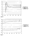
- Figures 6-8 show results obtained according to an embodiment of the present invention.
- the trace 60 is the lens temperature (CtLnsTempFM)
- trace 61 is the temperature of the setpoint of the lens cooling water (CtLcsSetp)
- trace 62 is the temperature of the reference frame at the measure side (CtMfMeasTemp)
- trace 63 is the temperature of the reference frame at the expose side (CtMfExpTemp).
- Figure 6 shows experimental results achieved according to an embodiment of the present invention, in which the reference frame MF was aluminium.
- the temperature recovery is achieved using the lens sensor 22 and during exposure of a substrate W the reference frame MF sensor 21 is used. It is seen that the long term drift of the lens PL is not corrected in this measurement.
- both the sensor 21 which senses the temperature of the reference frame MF and the sensor 22 which senses the temperature of the projection lens PL are used in the control algorithm to prevent this long term lens temperature drift observed in Figure 6.
- Figure 7 shows detail of the results shown in Figure 6.
- Figure 7 shows the results around the exposure phase. The correction for the short term experimental drift can be seen.
- an exposure was started resulting in an environmental temperature increase of about 20 mK, this results in a temperature decrease of the LCW setpoint.
- the covers were removed from the electronic cabinets resulting in a sudden decrease of the environmental air. This is accounted for by the control by a sudden temperature increase of the setpoint.
- the temperature of the reference frame MF is seen to remain stable.
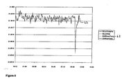
- Figure 8 shows detail of the results shown in Figure 6.
- Figure 8 shows the experimental results zoomed in at the reference frame MF temperature. It can be seen that at all times the temperature fluctuation are in the order of 0.1 mK, which corresponds to a measurement error of 1 nm, except when the covers are removed. It is commented that the removal of the covers can be regarded as an exceptional situation. Even then, the results shown in Figure 8 show that the recovery for this action is very quick. While specific embodiments of the invention have been described above, it will be appreciated that the invention may be practiced otherwise than as described. The description is not intended to limit the invention.
Landscapes
- Physics & Mathematics (AREA)
- Health & Medical Sciences (AREA)
- General Physics & Mathematics (AREA)
- Engineering & Computer Science (AREA)
- Environmental & Geological Engineering (AREA)
- Public Health (AREA)
- Epidemiology (AREA)
- Life Sciences & Earth Sciences (AREA)
- Atmospheric Sciences (AREA)
- Toxicology (AREA)
- Optics & Photonics (AREA)
- Computer Networks & Wireless Communication (AREA)
- Exposure And Positioning Against Photoresist Photosensitive Materials (AREA)
- Exposure Of Semiconductors, Excluding Electron Or Ion Beam Exposure (AREA)
- Container, Conveyance, Adherence, Positioning, Of Wafer (AREA)
Applications Claiming Priority (4)
| Application Number | Priority Date | Filing Date | Title |
|---|---|---|---|
| US735847 | 1985-05-20 | ||
| NL0300798 | 2003-11-13 | ||
| WOPCT/NL03/00798 | 2003-11-13 | ||
| US10/735,847 US7061579B2 (en) | 2003-11-13 | 2003-12-16 | Lithographic apparatus and device manufacturing method |
Publications (3)
| Publication Number | Publication Date |
|---|---|
| EP1531364A2 true EP1531364A2 (de) | 2005-05-18 |
| EP1531364A3 EP1531364A3 (de) | 2005-05-25 |
| EP1531364B1 EP1531364B1 (de) | 2013-07-17 |
Family
ID=34437049
Family Applications (1)
| Application Number | Title | Priority Date | Filing Date |
|---|---|---|---|
| EP04078004.1A Expired - Lifetime EP1531364B1 (de) | 2003-11-13 | 2004-11-02 | Lithographisches Gerät und Verfahren zur Herstellung einer Vorrichtung |
Country Status (7)
| Country | Link |
|---|---|
| US (2) | US7061579B2 (de) |
| EP (1) | EP1531364B1 (de) |
| JP (3) | JP4452160B2 (de) |
| KR (1) | KR100632424B1 (de) |
| CN (1) | CN100595674C (de) |
| SG (1) | SG112064A1 (de) |
| TW (1) | TWI251131B (de) |
Cited By (10)
| Publication number | Priority date | Publication date | Assignee | Title |
|---|---|---|---|---|
| EP1542076A2 (de) * | 2003-12-08 | 2005-06-15 | ASML Netherlands B.V. | Lithographischer Apparat und Verfahren zur Herstellung einer Vorrichtung |
| WO2007128835A1 (en) * | 2006-05-09 | 2007-11-15 | Carl Zeiss Smt Ag | Optical imaging device with thermal attenuation |
| WO2010017952A3 (en) * | 2008-08-11 | 2010-04-22 | Carl Zeiss Smt Ag | Low-contamination optical arrangement |
| US8107052B2 (en) | 2006-04-04 | 2012-01-31 | Canon Kabushiki Kaisha | Exposure apparatus and device manufacturing method |
| WO2016041573A1 (de) * | 2014-09-15 | 2016-03-24 | Carl Zeiss Smt Gmbh | Verbindungsanordnung zum kraftschlüssigen verbinden von keramikbauteilen |
| DE102017219151A1 (de) | 2017-10-25 | 2019-04-25 | Carl Zeiss Smt Gmbh | Verfahren zum Temperieren einer Komponente |
| US10345710B2 (en) | 2004-01-20 | 2019-07-09 | Carl Zeiss Smt Gmbh | Microlithographic projection exposure apparatus and measuring device for a projection lens |
| DE102018201320A1 (de) | 2018-01-29 | 2019-08-01 | Carl Zeiss Smt Gmbh | Verfahren zum Temperieren einer Komponente |
| WO2020164868A1 (en) * | 2019-02-11 | 2020-08-20 | Asml Netherlands B.V. | Lithographic apparatus and method with a thermal control system |
| US11022903B2 (en) | 2017-10-25 | 2021-06-01 | Carl Zeiss Smt Gmbh | Method for temperature control of a component |
Families Citing this family (21)
| Publication number | Priority date | Publication date | Assignee | Title |
|---|---|---|---|---|
| JP4371822B2 (ja) * | 2004-01-06 | 2009-11-25 | キヤノン株式会社 | 露光装置 |
| JP4429023B2 (ja) * | 2004-01-07 | 2010-03-10 | キヤノン株式会社 | 露光装置及びデバイス製造方法 |
| EP1898241A4 (de) * | 2005-06-14 | 2010-11-03 | Nikon Corp | Optisches element, haltevorrichtung für ein optisches element, belichtungsvorrichtung und bauelementherstellungsverfahren |
| KR100647517B1 (ko) | 2005-08-26 | 2006-11-23 | (주)마스터이미지 | 셀 구조 패러랙스-배리어 및 이를 이용하는 입체영상 표시장치 |
| JP2009517627A (ja) * | 2005-11-30 | 2009-04-30 | コーニンクレッカ フィリップス エレクトロニクス エヌ ヴィ | 機械温度をより正確に調節するための熱流の局部的制御 |
| US20070185216A1 (en) | 2006-02-09 | 2007-08-09 | Marcia Snyder | Antiviral method |
| US8760621B2 (en) * | 2007-03-12 | 2014-06-24 | Asml Netherlands B.V. | Lithographic apparatus and method |
| US7804579B2 (en) * | 2007-06-21 | 2010-09-28 | Asml Netherlands B.V. | Control system, lithographic projection apparatus, method of controlling a support structure, and a computer program product |
| WO2009046955A2 (en) | 2007-10-09 | 2009-04-16 | Carl Zeiss Smt Ag | Device for controlling temperature of an optical element |
| KR101768983B1 (ko) | 2008-06-10 | 2017-08-17 | 에이에스엠엘 네델란즈 비.브이. | 광학 요소를 열적으로 컨디셔닝하는 방법 및 시스템 |
| WO2010037575A1 (en) | 2008-09-30 | 2010-04-08 | Asml Netherlands B.V. | Projection system and lithographic apparatus |
| JP5783811B2 (ja) * | 2010-07-06 | 2015-09-24 | キヤノン株式会社 | 成膜装置 |
| CN102841507B (zh) * | 2011-06-23 | 2014-06-25 | 虎尾科技大学 | 激光直写式纳米周期性结构图案制造设备 |
| DE102011114254B4 (de) * | 2011-09-26 | 2014-11-27 | Carl Zeiss Smt Gmbh | Messvorrichtung und optisches System mit einer solchen |
| CN103324032B (zh) * | 2012-03-22 | 2015-07-22 | 上海微电子装备有限公司 | 一种多面体主基板及其制造方法和加工方法 |
| CN103777303B (zh) * | 2012-10-19 | 2016-02-03 | 上海微电子装备有限公司 | 长条镜安装装置 |
| DE102015211286A1 (de) * | 2015-06-18 | 2016-12-22 | Carl Zeiss Smt Gmbh | Abbildungssystem und verfahren |
| CN106931878A (zh) | 2015-12-31 | 2017-07-07 | 上海微电子装备有限公司 | 一种干涉仪测量装置及其控制方法 |
| CN109791380B (zh) * | 2016-10-04 | 2021-04-16 | Asml荷兰有限公司 | 对准系统的无热化 |
| CN109856921A (zh) * | 2017-11-30 | 2019-06-07 | 上海微电子装备(集团)股份有限公司 | 光刻装置及其主基板结构与主基板单元 |
| DE102021201258A1 (de) | 2021-02-10 | 2022-08-11 | Carl Zeiss Smt Gmbh | Verfahren zum Heizen eines optischen Elements in einer mikrolithographischen Projektionsbelichtungsanlage, sowie optisches System |
Family Cites Families (34)
| Publication number | Priority date | Publication date | Assignee | Title |
|---|---|---|---|---|
| JPH03198320A (ja) * | 1989-12-27 | 1991-08-29 | Nikon Corp | 投影光学装置 |
| US6020950A (en) * | 1992-02-24 | 2000-02-01 | Nikon Corporation | Exposure method and projection exposure apparatus |
| KR0139039B1 (ko) * | 1993-06-30 | 1998-06-01 | 미타라이 하지메 | 노광장치와 이것을 이용한 디바이스 제조방법 |
| US5953105A (en) * | 1995-05-30 | 1999-09-14 | U.S. Philips Corporation | Positioning device with a reference frame for a measuring system, and a lithographic device provided with such a positioning device |
| US5883704A (en) * | 1995-08-07 | 1999-03-16 | Nikon Corporation | Projection exposure apparatus wherein focusing of the apparatus is changed by controlling the temperature of a lens element of the projection optical system |
| US5877843A (en) * | 1995-09-12 | 1999-03-02 | Nikon Corporation | Exposure apparatus |
| US5644137A (en) * | 1996-03-04 | 1997-07-01 | Waggener; Herbert A. | Stabilizing support mechanism for electron beam apparatus |
| JPH10209040A (ja) * | 1996-11-25 | 1998-08-07 | Nikon Corp | 露光装置 |
| WO1998028665A1 (en) * | 1996-12-24 | 1998-07-02 | Koninklijke Philips Electronics N.V. | Two-dimensionally balanced positioning device with two object holders, and lithographic device provided with such a positioning device |
| JP3437406B2 (ja) * | 1997-04-22 | 2003-08-18 | キヤノン株式会社 | 投影露光装置 |
| KR100250152B1 (ko) * | 1997-11-15 | 2000-03-15 | 유무성 | 노광장치 |
| AU1260099A (en) | 1997-11-25 | 1999-06-15 | Nikon Corporation | Projection exposure system |
| AU1261699A (en) * | 1997-11-28 | 1999-06-16 | Nikon Corporation | Substrate retaining apparatus and exposure apparatus using the same |
| JPH11354431A (ja) * | 1998-06-11 | 1999-12-24 | Nikon Corp | 投影露光装置及び半導体デバイスの製造方法 |
| US6262795B1 (en) * | 1998-08-28 | 2001-07-17 | Philip Semiconductors, Inc. | Apparatus and method for the improvement of illumination uniformity in photolithographic systems |
| US6118599A (en) * | 1998-11-03 | 2000-09-12 | Nikon Corporation | Hybrid optical barrel |
| JP2001126977A (ja) * | 1999-10-27 | 2001-05-11 | Nikon Corp | ステージ装置および露光装置ならびに回路デバイス製造方法 |
| TWI231405B (en) * | 1999-12-22 | 2005-04-21 | Asml Netherlands Bv | Lithographic projection apparatus, position detection device, and method of manufacturing a device using a lithographic projection apparatus |
| US6621556B2 (en) * | 2000-02-28 | 2003-09-16 | Nikon Corporation | Projection exposure apparatus and manufacturing and adjusting methods thereof |
| JP2001244178A (ja) * | 2000-02-29 | 2001-09-07 | Canon Inc | 露光装置および露光方法ならびにデバイス製造方法 |
| US6630984B2 (en) * | 2000-08-03 | 2003-10-07 | Asml Netherlands B.V. | Lithographic apparatus, device manufacturing method, and device manufactured thereby |
| EP1178357A1 (de) * | 2000-08-03 | 2002-02-06 | Asm Lithography B.V. | Lithographischer Apparat |
| US6473245B1 (en) * | 2000-08-10 | 2002-10-29 | Nikon Corporation | Catadioptric lens barrel structure having a plurality of support platforms and method of making the same |
| US6577457B1 (en) * | 2000-08-10 | 2003-06-10 | Nikon Corporation | Catadioptric lens barrel structure having a kinematic alignment structure and method for aligning two planar surfaces |
| US6549347B1 (en) * | 2000-08-10 | 2003-04-15 | Nikon Corporation | Catadioptric lens barrel structure |
| US6449106B1 (en) * | 2000-08-10 | 2002-09-10 | Nikon Corporation | Catadioptric lens barrel structure having a support structure to maintain alignment of a plurality of sub-barrels |
| US6774981B1 (en) | 2000-09-08 | 2004-08-10 | Nikon Corporation | Modular exposure apparatus with removable optical device and improved isolation of the optical device |
| JP2002217095A (ja) * | 2000-11-14 | 2002-08-02 | Canon Inc | 露光装置、半導体デバイス製造方法、半導体製造工場及び露光装置の保守方法並びに位置検出装置 |
| JP2002190438A (ja) * | 2000-12-21 | 2002-07-05 | Nikon Corp | 露光装置 |
| US6538720B2 (en) * | 2001-02-28 | 2003-03-25 | Silicon Valley Group, Inc. | Lithographic tool with dual isolation system and method for configuring the same |
| US20020155364A1 (en) * | 2001-04-20 | 2002-10-24 | David Trost | Method and system to achieve thermal transfer between a workpiece and a heated body disposed in a chamber |
| US6674512B2 (en) * | 2001-08-07 | 2004-01-06 | Nikon Corporation | Interferometer system for a semiconductor exposure system |
| US6876452B2 (en) * | 2001-12-13 | 2005-04-05 | Zygo Corporation | Apparatus and methods for high accuracy metrology and positioning of a body |
| US20040204777A1 (en) * | 2003-04-14 | 2004-10-14 | Alon Harpaz | Precision motion control using feed forward of acceleration |
-
2003
- 2003-12-16 US US10/735,847 patent/US7061579B2/en not_active Expired - Lifetime
-
2004
- 2004-11-02 EP EP04078004.1A patent/EP1531364B1/de not_active Expired - Lifetime
- 2004-11-10 SG SG200406895A patent/SG112064A1/en unknown
- 2004-11-12 US US10/986,182 patent/US7130019B2/en not_active Expired - Lifetime
- 2004-11-12 KR KR1020040092548A patent/KR100632424B1/ko not_active Expired - Fee Related
- 2004-11-12 CN CN200410094716.9A patent/CN100595674C/zh not_active Expired - Lifetime
- 2004-11-12 TW TW093134730A patent/TWI251131B/zh not_active IP Right Cessation
- 2004-11-12 JP JP2004328305A patent/JP4452160B2/ja not_active Expired - Fee Related
-
2008
- 2008-09-29 JP JP2008251029A patent/JP4900970B2/ja not_active Expired - Fee Related
-
2011
- 2011-09-13 JP JP2011199359A patent/JP5619699B2/ja not_active Expired - Fee Related
Non-Patent Citations (1)
| Title |
|---|
| None |
Cited By (21)
| Publication number | Priority date | Publication date | Assignee | Title |
|---|---|---|---|---|
| EP1542076A2 (de) * | 2003-12-08 | 2005-06-15 | ASML Netherlands B.V. | Lithographischer Apparat und Verfahren zur Herstellung einer Vorrichtung |
| US10345710B2 (en) | 2004-01-20 | 2019-07-09 | Carl Zeiss Smt Gmbh | Microlithographic projection exposure apparatus and measuring device for a projection lens |
| TWI397778B (zh) * | 2006-04-04 | 2013-06-01 | 佳能股份有限公司 | 曝光設備和製造裝置的方法 |
| US8107052B2 (en) | 2006-04-04 | 2012-01-31 | Canon Kabushiki Kaisha | Exposure apparatus and device manufacturing method |
| US20180181007A1 (en) * | 2006-05-09 | 2018-06-28 | Carl Zeiss Smt Gmbh | Optical imaging device with thermal attenuation |
| CN101479665B (zh) * | 2006-05-09 | 2012-07-11 | 卡尔蔡司Smt有限责任公司 | 带热衰减装置的光学成像装置 |
| US9810996B2 (en) | 2006-05-09 | 2017-11-07 | Carl Zeiss Smt Gmbh | Optical imaging device with thermal attenuation |
| WO2007128835A1 (en) * | 2006-05-09 | 2007-11-15 | Carl Zeiss Smt Ag | Optical imaging device with thermal attenuation |
| US9316930B2 (en) | 2008-08-11 | 2016-04-19 | Carl Zeiss Smt Gmbh | Low-contamination optical arrangement |
| WO2010017952A3 (en) * | 2008-08-11 | 2010-04-22 | Carl Zeiss Smt Ag | Low-contamination optical arrangement |
| WO2016041573A1 (de) * | 2014-09-15 | 2016-03-24 | Carl Zeiss Smt Gmbh | Verbindungsanordnung zum kraftschlüssigen verbinden von keramikbauteilen |
| TWI694310B (zh) * | 2014-09-15 | 2020-05-21 | 德商卡爾蔡司Smt有限公司 | 陶瓷元件之間力合連接的連接配置及力合連接的方法 |
| TWI737268B (zh) * | 2014-09-15 | 2021-08-21 | 德商卡爾蔡司Smt有限公司 | 陶瓷元件之間力合連接的連接配置及力合連接的方法 |
| US10571813B2 (en) | 2014-09-15 | 2020-02-25 | Carl Zeiss Smt Gmbh | Connection arrangement for a force-fit connection between ceramic components |
| DE102017219151A1 (de) | 2017-10-25 | 2019-04-25 | Carl Zeiss Smt Gmbh | Verfahren zum Temperieren einer Komponente |
| US11022903B2 (en) | 2017-10-25 | 2021-06-01 | Carl Zeiss Smt Gmbh | Method for temperature control of a component |
| US11372341B2 (en) | 2017-10-25 | 2022-06-28 | Carl Zeiss Smt Gmbh | Method for temperature control of a component |
| DE102018201320A1 (de) | 2018-01-29 | 2019-08-01 | Carl Zeiss Smt Gmbh | Verfahren zum Temperieren einer Komponente |
| WO2020164868A1 (en) * | 2019-02-11 | 2020-08-20 | Asml Netherlands B.V. | Lithographic apparatus and method with a thermal control system |
| KR20210124998A (ko) * | 2019-02-11 | 2021-10-15 | 에이에스엠엘 네델란즈 비.브이. | 열 제어 시스템을 갖는 리소그래피 장치 및 방법 |
| TWI849052B (zh) * | 2019-02-11 | 2024-07-21 | 荷蘭商Asml荷蘭公司 | 具有熱控制系統之微影裝置及方法 |
Also Published As
| Publication number | Publication date |
|---|---|
| JP5619699B2 (ja) | 2014-11-05 |
| TW200528930A (en) | 2005-09-01 |
| JP2009016868A (ja) | 2009-01-22 |
| CN1617048A (zh) | 2005-05-18 |
| US20050105070A1 (en) | 2005-05-19 |
| SG112064A1 (en) | 2005-06-29 |
| US7130019B2 (en) | 2006-10-31 |
| CN100595674C (zh) | 2010-03-24 |
| JP4452160B2 (ja) | 2010-04-21 |
| JP2012028797A (ja) | 2012-02-09 |
| JP4900970B2 (ja) | 2012-03-21 |
| EP1531364B1 (de) | 2013-07-17 |
| US7061579B2 (en) | 2006-06-13 |
| TWI251131B (en) | 2006-03-11 |
| KR20050046626A (ko) | 2005-05-18 |
| JP2005150732A (ja) | 2005-06-09 |
| EP1531364A3 (de) | 2005-05-25 |
| US20050151954A1 (en) | 2005-07-14 |
| KR100632424B1 (ko) | 2006-10-09 |
Similar Documents
| Publication | Publication Date | Title |
|---|---|---|
| US7130019B2 (en) | Lithographic apparatus and device manufacturing method | |
| US6977713B2 (en) | Lithographic apparatus and device manufacturing method | |
| US7738074B2 (en) | Lithographic apparatus and device manufacturing method | |
| US9164401B2 (en) | Projection system and lithographic apparatus | |
| US7489388B2 (en) | Lithographic apparatus and device manufacturing method | |
| US7545478B2 (en) | Lithographic apparatus, thermal conditioning system, and method for manufacturing a device | |
| EP1498781B1 (de) | Lithografisches Immersionsgerät und Verfahren zur Herstellung einer Vorrichtung |
Legal Events
| Date | Code | Title | Description |
|---|---|---|---|
| PUAI | Public reference made under article 153(3) epc to a published international application that has entered the european phase |
Free format text: ORIGINAL CODE: 0009012 |
|
| PUAL | Search report despatched |
Free format text: ORIGINAL CODE: 0009013 |
|
| AK | Designated contracting states |
Kind code of ref document: A2 Designated state(s): AT BE BG CH CY CZ DE DK EE ES FI FR GB GR HU IE IS IT LI LU MC NL PL PT RO SE SI SK TR |
|
| AX | Request for extension of the european patent |
Extension state: AL HR LT LV MK YU |
|
| AK | Designated contracting states |
Kind code of ref document: A3 Designated state(s): AT BE BG CH CY CZ DE DK EE ES FI FR GB GR HU IE IS IT LI LU MC NL PL PT RO SE SI SK TR |
|
| AX | Request for extension of the european patent |
Extension state: AL HR LT LV MK YU |
|
| 17P | Request for examination filed |
Effective date: 20051027 |
|
| AKX | Designation fees paid |
Designated state(s): DE FR GB IT NL |
|
| 17Q | First examination report despatched |
Effective date: 20110222 |
|
| GRAP | Despatch of communication of intention to grant a patent |
Free format text: ORIGINAL CODE: EPIDOSNIGR1 |
|
| GRAP | Despatch of communication of intention to grant a patent |
Free format text: ORIGINAL CODE: EPIDOSNIGR1 |
|
| GRAS | Grant fee paid |
Free format text: ORIGINAL CODE: EPIDOSNIGR3 |
|
| GRAA | (expected) grant |
Free format text: ORIGINAL CODE: 0009210 |
|
| AK | Designated contracting states |
Kind code of ref document: B1 Designated state(s): DE FR GB IT NL |
|
| REG | Reference to a national code |
Ref country code: GB Ref legal event code: FG4D |
|
| REG | Reference to a national code |
Ref country code: DE Ref legal event code: R096 Ref document number: 602004042730 Country of ref document: DE Effective date: 20130912 |
|
| REG | Reference to a national code |
Ref country code: NL Ref legal event code: VDEP Effective date: 20130717 |
|
| PG25 | Lapsed in a contracting state [announced via postgrant information from national office to epo] |
Ref country code: NL Free format text: LAPSE BECAUSE OF FAILURE TO SUBMIT A TRANSLATION OF THE DESCRIPTION OR TO PAY THE FEE WITHIN THE PRESCRIBED TIME-LIMIT Effective date: 20130717 |
|
| PLBE | No opposition filed within time limit |
Free format text: ORIGINAL CODE: 0009261 |
|
| STAA | Information on the status of an ep patent application or granted ep patent |
Free format text: STATUS: NO OPPOSITION FILED WITHIN TIME LIMIT |
|
| PG25 | Lapsed in a contracting state [announced via postgrant information from national office to epo] |
Ref country code: IT Free format text: LAPSE BECAUSE OF FAILURE TO SUBMIT A TRANSLATION OF THE DESCRIPTION OR TO PAY THE FEE WITHIN THE PRESCRIBED TIME-LIMIT Effective date: 20130717 |
|
| 26N | No opposition filed |
Effective date: 20140422 |
|
| GBPC | Gb: european patent ceased through non-payment of renewal fee |
Effective date: 20131102 |
|
| REG | Reference to a national code |
Ref country code: DE Ref legal event code: R097 Ref document number: 602004042730 Country of ref document: DE Effective date: 20140422 |
|
| PG25 | Lapsed in a contracting state [announced via postgrant information from national office to epo] |
Ref country code: GB Free format text: LAPSE BECAUSE OF NON-PAYMENT OF DUE FEES Effective date: 20131102 |
|
| REG | Reference to a national code |
Ref country code: FR Ref legal event code: PLFP Year of fee payment: 12 |
|
| REG | Reference to a national code |
Ref country code: FR Ref legal event code: PLFP Year of fee payment: 13 |
|
| REG | Reference to a national code |
Ref country code: FR Ref legal event code: PLFP Year of fee payment: 14 |
|
| PGFP | Annual fee paid to national office [announced via postgrant information from national office to epo] |
Ref country code: DE Payment date: 20191121 Year of fee payment: 16 |
|
| PGFP | Annual fee paid to national office [announced via postgrant information from national office to epo] |
Ref country code: FR Payment date: 20191120 Year of fee payment: 16 |
|
| REG | Reference to a national code |
Ref country code: DE Ref legal event code: R119 Ref document number: 602004042730 Country of ref document: DE |
|
| PG25 | Lapsed in a contracting state [announced via postgrant information from national office to epo] |
Ref country code: FR Free format text: LAPSE BECAUSE OF NON-PAYMENT OF DUE FEES Effective date: 20201130 |
|
| PG25 | Lapsed in a contracting state [announced via postgrant information from national office to epo] |
Ref country code: DE Free format text: LAPSE BECAUSE OF NON-PAYMENT OF DUE FEES Effective date: 20210601 |