EP1531425A2 - Computerunterstützte Bildaufnahme und Diagnosesystem - Google Patents
Computerunterstützte Bildaufnahme und Diagnosesystem Download PDFInfo
- Publication number
- EP1531425A2 EP1531425A2 EP04256955A EP04256955A EP1531425A2 EP 1531425 A2 EP1531425 A2 EP 1531425A2 EP 04256955 A EP04256955 A EP 04256955A EP 04256955 A EP04256955 A EP 04256955A EP 1531425 A2 EP1531425 A2 EP 1531425A2
- Authority
- EP
- European Patent Office
- Prior art keywords
- image
- detection object
- unit
- computer aided
- diagnosis system
- Prior art date
- Legal status (The legal status is an assumption and is not a legal conclusion. Google has not performed a legal analysis and makes no representation as to the accuracy of the status listed.)
- Granted
Links
Images



Classifications
-
- A—HUMAN NECESSITIES
- A61—MEDICAL OR VETERINARY SCIENCE; HYGIENE
- A61B—DIAGNOSIS; SURGERY; IDENTIFICATION
- A61B6/00—Apparatus or devices for radiation diagnosis; Apparatus or devices for radiation diagnosis combined with radiation therapy equipment
- A61B6/02—Arrangements for diagnosis sequentially in different planes; Stereoscopic radiation diagnosis
- A61B6/03—Computed tomography [CT]
-
- G—PHYSICS
- G06—COMPUTING OR CALCULATING; COUNTING
- G06T—IMAGE DATA PROCESSING OR GENERATION, IN GENERAL
- G06T7/00—Image analysis
- G06T7/0002—Inspection of images, e.g. flaw detection
- G06T7/0012—Biomedical image inspection
-
- G—PHYSICS
- G06—COMPUTING OR CALCULATING; COUNTING
- G06T—IMAGE DATA PROCESSING OR GENERATION, IN GENERAL
- G06T12/00—Tomographic reconstruction from projections
- G06T12/30—Image post-processing, e.g. metal artefact correction
-
- G—PHYSICS
- G06—COMPUTING OR CALCULATING; COUNTING
- G06T—IMAGE DATA PROCESSING OR GENERATION, IN GENERAL
- G06T2207/00—Indexing scheme for image analysis or image enhancement
- G06T2207/10—Image acquisition modality
- G06T2207/10072—Tomographic images
- G06T2207/10081—Computed x-ray tomography [CT]
-
- G—PHYSICS
- G06—COMPUTING OR CALCULATING; COUNTING
- G06T—IMAGE DATA PROCESSING OR GENERATION, IN GENERAL
- G06T2207/00—Indexing scheme for image analysis or image enhancement
- G06T2207/30—Subject of image; Context of image processing
- G06T2207/30004—Biomedical image processing
Definitions
- the present invention is related to a computer aided image acquisition and diagnosis system, and more specifically to a computer aided image acquisition and diagnosis system for imaging an object to obtain a diagnosis image from the projection data.
- X-ray CT computed tomography
- An X-ray CT is capable of imaging a number of tomographic images at once, thanks to the speed-up and parallelization of a scanned range.
- the tomographic images obtained from an X-ray CT or an MRI (magnetic resonance imaging) apparatuses may be processed with the methods such as three dimensional (3D) rendering, Colonography, and 3D MIP (minimum intensity projection) to reconstruct a 3D image.
- 3D three dimensional
- 3D MIP minimum intensity projection
- CAD computer aided diagnosis
- the tomographic imaging using an image acquisition system and the image processing using the CAD is being performed on a single shared console.
- the user may image the object and immediately process the tomographic image thus obtained without moving to another place, or waiting for a while.
- the reconstruction of image is facilitated by sharing the hard disk drive unit for storing the projection data of the X-ray CT apparatus.
- an object of the present invention is to provide a computer aided image acquisition and diagnosis system, which can generate images easily for reading and diagnosis from the tomographic images and filing.
- the computer aided image acquisition and diagnosis system in accordance with the present invention relates to an computer aided image acquisition and diagnosis system for imaging an object and for obtaining a diagnostic image from the projection data thereof, and includes a selector means for selecting a detection object to be anticipated prior to imaging; a scanner means for scanning the object placed in position; an image processing means for generating a tomographic image of the object from the projection data obtained by the scanner means; an extractor means for extracting the detection object selected in the selector means from within the tomographic image generated; and a display means for displaying the detection object extracted by the tomographic image and the extractor means.
- the selector means selects the detection object to be anticipated prior to scanning.
- the scanning means scans the object placed in position.
- the image processing means generates a tomographic image of the object from the projection data obtained from the scanner means.
- the extractor means extracts the detection object selected by the selector means from within the tomographic image generated.
- the display means displays the detection object thus extracted by the extractor means.
- FIG. 1 there is shown a schematic block diagram of an X-ray CT apparatus 1 in accordance with the preferred embodiment.
- the X-ray CT apparatus 1 corresponds to one preferred embodiment of the computer aided image acquisition and diagnosis system in accordance with the present invention.
- the X-ray CT apparatus 1 includes a scanning gantry 10, a cradle 20, and an operator console 30.
- the scanning gantry 10 is also referred to as simply a "gantry" 10.
- the scanning gantry 10 corresponds to one preferred embodiment of the scanning means in accordance with the present invention.
- the scanning gantry 10 includes an X-ray irradiation source 12, and an X-ray detector 14 mounted in opposition to the X-ray source 12 on the other side of the object.
- the scanning gantry 10 revolves around the object with a predetermined rotating axis being as a center, to irradiate X-ray from the X-ray source 12 and to detect the X-ray transmitted through the object by the X-ray detector 14.
- the X-ray source 12 corresponds to a preferred embodiment of the X-ray irradiation unit in accordance with the present invention
- the X-ray detector 14 corresponds to a preferred embodiment of the X-ray detector unit.
- the cradle 20 mounts a subject.
- the cradle 20 is placed such that the imaging area of the subject can be placed within the movable range of the scanning gantry 10.
- the cradle 20 is controlled by the operator console 30 of the relative distance to the scanning gantry 10.
- the operator console 30 is connected to both the scanning gantry 10 and to the cradle 20.
- the operator console 30 is provided for controlling the movement and scanning of the scanning gantry 10 as well as the relative distance between the cradle 20 and the scanning gantry 10.
- the operator console 30 may be achieved with a console table, a display screen, a keyboard, and so on.
- the operator console 30 includes a control unit 32, a display device unit 34, a central processing unit 36, a storage device unit 38, and an image processing unit 40, a data collector unit 46, and CAD 50.
- the data collector unit 46 is connected to the X-ray detector 14 of the scanning gantry 10 and to the central processing unit 36.
- the data collector unit 46 collects the projection data detected by the X-ray detector 14 of the scanning gantry 10 to output to the central processing unit 36.
- the storage device unit 38 is connected to the central processing unit 36.
- the storage device unit 38 stores data such as date, name of subject, imaging region along with the reconstructed image.
- the data and image stored therein can be retrieved according to the instruction from the central processing unit 36.
- the storage device unit 38 can be achieved by for example a memory.
- the control unit 32 is connected to the scanning gantry 10, cradle 20, and the central processing unit 36.
- the control unit 32 controls the operation and positioning of the scanning gantry 10 and the cradle 20 according to the instruction from the central processing unit 36.
- the control unit 32 can be achieved by for example a CPU.
- the CAD 50 includes a selector unit 52 and an extractor unit 54.
- the CAD 50 is connected to the central processing unit 36 and is operated by the instruction from the central processing unit 36.
- the CAD 50 for example selects a detection object to be anticipated.
- the CAD 50 also extracts the detection object in the image output from the central processing unit 36.
- the CAD 50 can be achieved by for example a program.
- the selector unit 52 includes a database which stores parameters including typical forms and tones of shades known in various detection objects.
- the selector unit 52 corresponds to a preferred embodiment of the selector means in accordance with the present invention.
- the extractor unit 54 extracts the detection object selected by the selector unit 52 from the tomographic image data output from the central processing unit 36.
- the extractor unit 54 corresponds to a preferred embodiment of the extractor means in accordance with the present invention.
- the image-processing unit 40 includes a first reconstruction unit 42 and a second reconstruction unit 44.
- the image-processing unit 40 receives the projection data from the central processing unit 36 to generate a tomographic image of the object.
- the image-processing unit 40 receives the tomographic image data with the detection object extracted in the CAD 50 through the central processing unit 36 to generate the image of the detection object based on the set conditions in the CAD 50.
- the image-processing unit 40 transmits thus generated images to the central processing unit 36.
- the image-processing unit 40 can be achieved by for example a program. It should be noted here that the first reconstruction unit 42 and the second reconstruction unit 44 in the image-processing unit 40 may be formed by independent programs.
- the image-processing unit 40 corresponds to a preferred embodiment of the image processing means in accordance with the present invention.
- the first reconstruction unit 42 performs the image reconstruction processing on the projection data output from the central processing unit 36, based on the tomographic image generation conditions predetermined in the selector unit 52, to generate the tomographic image of each slice plane.
- the first reconstruction unit 42 outputs thus generated tomographic image to the central processing unit 36.
- the image generated in the first reconstruction unit 42 is referred to as the "tomographic image" herein below.
- the second reconstruction unit 44 receives the image data of the detection object extracted in the CAD 50 through the central processing unit 36.
- the second reconstruction unit 44 performs the image reconstruction processing on the image data or the projection data extracted by the CAD 50, based on the conditions set in the selector unit 52. More specifically, the second reconstruction unit 44 generates an image of detection object with the altered imaging view area and shade range of the tomographic image generated by the first reconstruction unit 42. The second reconstruction unit 44 further distinguishes the interface between the detection object and its surroundings.
- the second reconstruction unit 44 outputs thus generated image to the central processing unit 36.
- the image generated by the second reconstruction unit 44 is referred to as a "detection object image" herein below.
- the display device unit 34 is connected to the central processing unit 36.
- the display device unit 34 displays, based on the instruction from the central processing unit 36, images generated by the image processing unit 40, detection objects extracted by the CAD 50, and any other information.
- the display device unit 34 displays the detection object in a different color from the surrounding area, based on the instruction from the central processing unit 36.
- the display device unit 34 corresponds to a preferred embodiment of the display means in accordance with the present invention.
- the central processing unit 36 outputs the projection data input into the data collector unit 46 to the image-processing unit 40.
- the central processing unit 36 outputs the image data from the image-processing unit 40 to the CAD 50.
- the central processing unit 36 also outputs the image generated and extracted by the image-processing unit 40 and the CAD 50 to the storage device unit 38.
- the central processing unit 36 outputs to the display device unit 34 the image generated by the image processing unit 40 and the detection object detected by the CAD 50.
- the central processing unit 36 calculates a volume of the detection object extracted based on the 3D image.
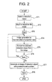
- Fig. 2 shows a flow chart illustrating the operation of the X-ray CT apparatus 1 in accordance with the preferred embodiment of the present invention.
- the user operates the operator console 30 to select in the selector unit 52 of the CAD 50 through the central processing unit 36 the detection object to be anticipated for the subject (ST 1).
- lung tumor is set to the detection object.
- the user sets the field of view (FOV), window level (W/L), window width (W/W), magnification ratio, etc for the parameters to generate the tomographic image and detection object image.
- FOV field of view
- W/L window level
- W/W window width
- magnification ratio magnification ratio
- a condition set shown in Table 1 below can be set for the parameters for generating the tomographic image of subject and detection object image.
- the detection object area will be magnified to obtain an image of higher resolution. Also, by setting a smaller W/W, the upper and lower limits of the CT value is restricted to a narrow range, resulting in a higher contrast in the detection object image.
- the user mounts the subject on the cradle (ST 2). Thereafter, the user operates the operator console 30 to select the completion of steps ST1 and ST2. By doing this, the following steps will be performed under the control of the central processing unit 36.
- the scanning gantry 10 moves under the control of the central processing unit 36 while at the same time irradiating X-ray from the X-ray source 12 to scan the subject (ST 3).
- the X-ray detector 14 in turn collects analog data of the X-ray intensity.
- the X-ray detector 14 converts thus collected analog data to output to the data collector unit 46 as projection data.
- the data collector unit 46 outputs the projection data through the central processing unit 36 to the image-processing unit 40. At this point, the central processing unit 36 may output the projection data to the storage device unit 38. The storage device unit 38 may store the projection data.
- the first reconstruction unit 42 of the image processing unit 40 reconstruct the projection data based on the parameters shown in Table 1 to generate a plurality of tomographic images corresponding to the slice thickness in the imaging field of the subject (ST 4).
- the image-processing unit 40 outputs the generated tomographic image data to the central processing unit 36.
- the central processing unit 36 outputs the tomographic image data to the display device unit 34 to display the tomographic image on the display device unit 34 if necessary.
- the user may decide whether or not to proceed to the following processing based on the observation of the tomographic image.
- the central processing unit 36 outputs data of a plurality of generated tomographic images to the extractor unit 54 of the CAD 50.
- the extractor unit 54 extracts the detection object set by the selector unit 52 of the CAD 50 from within the tomographic image data (ST 5).
- the extractor unit 54 uses the characteristics parameters such as the form, partial form, and shadow of the lung tumor, stored in the selector unit 52 to seek any match in every tomographic image data.
- the selector unit 52 sets a predetermined threshold for each of characteristics parameters.
- the extractor unit 54 extracts a matrix that has a CT value beyond the set threshold from the tomographic image data.
- the extractor unit 54 then computes a continuous region in the extracted matrix to form candidates of tumor form and partial form, and compares them with the stored form in the selector unit 52.
- the extractor unit 54 selects a matched form as the detection object.
- the extractor unit 54 may otherwise compute the surface area of the continuous area to select as the detection object.
- the CAD 50 After the detection object is extracted from the tomographic image data, The CAD 50 outputs the tomographic image data to the central processing unit 36. The central processing unit 36 then outputs the tomographic image having the detection object extracted to the display device unit 34, and the user may determine whether or not to proceed to the following steps while observing the tomographic image with the detection object extracted.
- the central processing unit 36 retrieves the stored projection data from the storage device unit 38 based on the instruction from the extractor unit 54, to output the projection data to the first reconstruction unit 42 to redo the processing from the tomographic image generation (ST 4) step (ST 6).
- the data storage in the storage device unit 38 will be described later.
- the processing can be performed again from the desired step according to the decision of the user, as have been described above.
- an anticipated detection object might be selected in the step ST 1 to extract the detection object from the projection data stored in the first reconstruction unit 42, or the projection data might be retrieved again by changing the scanning area in the step ST 2.
- the central processing unit 36 outputs the tomographic image data with the detection object extracted to the second reconstruction unit 44.
- the second reconstruction unit 44 in turn follows the conditions set in the selector unit 52 in the step ST 1 (see Table 1) to generate an image having the region around the extracted detection object enlarged from the tomographic image data or projection data (ST 7).
- the image generated by the first reconstruction unit 42 and the image generated by the second reconstruction unit 44 may be generated such that the conditions such as FOV and W/W will be different.
- the second reconstruction unit 44 can detect the value beyond a predetermined threshold when the threshold of the CT value corresponding to each matrix is set for the generated detection object image, or identify the detection object from the surrounding area by determining the difference of CT values between the adjoining matrices.
- the second reconstruction unit 44 outputs thus generated enlarged image of the detection object to the central processing unit 36.
- the central processing unit 36 in turn outputs the enlarged image of the detection object to the display device unit 34, which displays the image.
- the display device unit 34 uses a different color for the detection object from the color for the surroundings.
- the user may read and diagnose the detection object displayed on the display unit.
- the user needs only selecting the imaging conditions in step ST 1 and step ST 2 and mounting the subject, and selecting whether or not proceeding the image processing, extracted and enlarged image of the detection object can be obtained.
- the central processing unit 36 outputs to the storage device unit 38 the image data including the projection data and the two dimensional images generated by the first reconstruction unit 42 and the second reconstruction unit 44.
- the storage device unit 38 stores the data (ST 8).
- the image data means the projection data, two dimensional image data, and three-dimensional image data that will be described later.
- the storage device unit 38 stores along with the image data, any data including the imaging condition such as computed volume of the detection object, imaging date, imaging purpose, subject name, imaging angle, as well as the number of images.
- the imaging condition such as computed volume of the detection object, imaging date, imaging purpose, subject name, imaging angle, as well as the number of images.
- the data stored in the storage device unit 38 can be retrieved under the control of the central processing unit 36.
- Fig. 3 shows a flow chart illustrating the operation of the computer aided image acquisition and diagnosis system 1 in accordance with the preferred embodiment.
- the user sets the conditions in a similar manner to the step ST 1 of Fig. 2, and specifies the display area and display magnification of the detection object.
- the detection object will be extracted on the operator console 30.
- the second reconstruction unit 44 generates a three-dimensional image of the detection object extracted.
- the user selects the generation of a three dimensional image in the step ST 1 of selecting the detection object, and previously selects any one of two methods of three dimensional image generation. Accordingly, the second reconstruction unit 44 will generate a three-dimensional image based on the previously selected process method at the time when the above step ST 6 is completed.
- Fig. 4 (a) and Fig. 4 (b) are schematic diagrams illustrating the first processing method A.
- the second reconstruction unit 44 uses every tomographic image with the detection object extracted, as similar to step ST 7, in accordance with the condition defined in step ST 1, to generate a plurality of two-dimensional images (ST 21).
- the generating condition of two-dimensional image can be as shown in Table 1.
- the second reconstruction unit 44 performs the interpolation on the plurality of two dimensional images with the detection object enlarged to generate a three dimensional image of the detection object (ST 22).
- the second reconstruction unit 44 outputs thus generated three-dimensional image to the display device unit 34 through the central processing unit 36, to display the image according to the display condition determined in step ST 1.
- the central processing unit 36 computes the volume of the detection object from the generated three-dimensional image (ST 25).
- Fig. 5 (a) and Fig. 5 (b) are schematic diagrams illustrating the second processing method B.
- the second reconstruction unit 44 receives from the central processing unit 36 the data of two dimensional images, reconstructed by the first reconstruction unit 42 and having the detection object extracted by the extractor unit 54.
- the second reconstruction unit 44 performs the interpolation on the received two dimensional image data to generate a three dimensional image (ST 23).
- the second reconstruction unit 44 generates the detection object image based on the condition set in step ST 1 for the generated three-dimensional image (ST 24).
- the central processing unit 36 outputs the detection object image to the display device unit 34, which in turn displays the generated three-dimensional image according to the specified area or magnification.
- the central processing unit 36 computes the volume of the detection object from within the generated three-dimensional image (ST 25).
- Fig. 6 shows a flow chart illustrating the operation of the X-ray CT apparatus 1 in accordance with the preferred embodiment of the present invention.
- the process steps will be performed under the control of the central processing unit 36 when the user decides whether or not to compare in step ST 1 and after the second reconstruction unit 44 generates the two or three-dimensional image of the detection object in the step ST 7 or ST 25.
- the storage device unit 38 seeks the image data of the same name of subject with reference to the image data, according to the instruction from the central processing unit 36 (ST 41).
- the storage device unit 38 furthermore seeks the image data of the same detection object of the same name of subject.
- the past image data will be processed in accordance with the current selection and display conditions to display on the display device unit 34 (ST 42).
- the central processing unit 36 outputs from the first reconstruction unit 42 to the first reconstruction unit 42 the stored past image data for example such as the projection data.
- the storage device unit 38 generates a tomographic image in a manner similar to step ST 4 shown in Fig. 2.
- the first reconstruction unit 42 outputs to the extractor unit 54 of the CAD 50 through the central processing unit 36 thus generated tomographic image data. Thereafter, in a manner similar to step ST 5 of Fig. 2, the extractor unit 54 extracts the detection object from within the tomographic image generated from the past image data, in accordance with the condition defined in step ST 1.
- the central processing unit 36 outputs from the extractor unit 54 to the second reconstruction unit 44 the image with the detection object extracted. Then, based on the currently selected condition in the selector unit 52, the second reconstruction unit 44 generates the image of the detection object. For example, the second reconstruction unit 44 will generate a three dimensional image, the central processing unit 36 will compute the volume of the detection object from thus generated three dimensional image.
- the central processing unit 36 outputs from the second reconstruction unit 44 to the display device unit 34 the past image and data having processed.
- the central processing unit 36 compares the image data and information data of the current imaging session with the image data and information data processed of the past imaging session (ST 43).
- the central processing unit 36 overlays the three dimensional image of the detection object imaged in the current session over the three dimensional image of the detection object imaged in the past session to identify the overlapped area of two three dimensional images. Then the central processing unit 36 outputs the identification result to the display device unit 34.
- the display device unit 34 based on the data received from the central processing unit 36, displays the overlapped area and unoverlapped area of two three dimensional images with different colors.
- the image-processing unit 40 uses the three-dimensional images to compute the volume of the detection object of both sessions to display the computation result on the display device unit 34.
- the operator console 30 compares the size and the like of the detection object and displays the result so as to facilitate the identification of the growth of the detection object such as a tumor by the user.
- the comparison may be performed with a typical case of the detection object to be anticipated.
- the user selects the image generation conditions including the detection object to be anticipated, FOV, W/W, W/L of the tomographic image and detection object image, and the like, prior to scanning the subject to be examined.
- the operator console 30 generates a tomographic image from the projection data obtained from a scan and generate a detection object image with the detection object extracted, which facilitates the user to read and diagnose, from the tomographic image generated.
- the user may need only to select the conditions prior to scanning. Since any operation can be directed from the operator console 30 of the X-ray CT apparatus, imaging efficiency will be improved.
- the imaging and image processing will be performed after the detection object to be anticipated and the image generation conditions will have been previously selected by the user, from the operator console 30, the time taken from the imaging to the reading can be saved even when a lot of images are to be imaged.
- the system facilitates the user to file and save the image.
- the imaging apparatus in accordance with the present invention is not limited to the above preferred embodiments.
- the imaging apparatus in accordance with the present invention has been described with specific embodiments in an X-ray CT apparatus, the present invention is equally applied to the angiographic imaging, MRI, and any imaging apparatuses having a scanning gantry.
Landscapes
- Engineering & Computer Science (AREA)
- Physics & Mathematics (AREA)
- Health & Medical Sciences (AREA)
- General Physics & Mathematics (AREA)
- Theoretical Computer Science (AREA)
- Medical Informatics (AREA)
- General Health & Medical Sciences (AREA)
- Nuclear Medicine, Radiotherapy & Molecular Imaging (AREA)
- Radiology & Medical Imaging (AREA)
- Life Sciences & Earth Sciences (AREA)
- Quality & Reliability (AREA)
- Computer Vision & Pattern Recognition (AREA)
- Biophysics (AREA)
- High Energy & Nuclear Physics (AREA)
- Optics & Photonics (AREA)
- Pathology (AREA)
- Biomedical Technology (AREA)
- Heart & Thoracic Surgery (AREA)
- Molecular Biology (AREA)
- Surgery (AREA)
- Animal Behavior & Ethology (AREA)
- Public Health (AREA)
- Veterinary Medicine (AREA)
- Apparatus For Radiation Diagnosis (AREA)
Applications Claiming Priority (2)
| Application Number | Priority Date | Filing Date | Title |
|---|---|---|---|
| JP2003384562 | 2003-11-14 | ||
| JP2003384562A JP4118786B2 (ja) | 2003-11-14 | 2003-11-14 | 画像撮影診断支援システム |
Publications (3)
| Publication Number | Publication Date |
|---|---|
| EP1531425A2 true EP1531425A2 (de) | 2005-05-18 |
| EP1531425A3 EP1531425A3 (de) | 2010-07-21 |
| EP1531425B1 EP1531425B1 (de) | 2014-05-14 |
Family
ID=34431485
Family Applications (1)
| Application Number | Title | Priority Date | Filing Date |
|---|---|---|---|
| EP04256955.8A Expired - Fee Related EP1531425B1 (de) | 2003-11-14 | 2004-11-10 | Computerunterstützte Bildaufnahme und Diagnosesystem |
Country Status (5)
| Country | Link |
|---|---|
| US (1) | US8194945B2 (de) |
| EP (1) | EP1531425B1 (de) |
| JP (1) | JP4118786B2 (de) |
| KR (1) | KR20050046585A (de) |
| CN (1) | CN100536775C (de) |
Cited By (6)
| Publication number | Priority date | Publication date | Assignee | Title |
|---|---|---|---|---|
| US7860283B2 (en) | 2006-10-25 | 2010-12-28 | Rcadia Medical Imaging Ltd. | Method and system for the presentation of blood vessel structures and identified pathologies |
| US7873194B2 (en) | 2006-10-25 | 2011-01-18 | Rcadia Medical Imaging Ltd. | Method and system for automatic analysis of blood vessel structures and pathologies in support of a triple rule-out procedure |
| US7940977B2 (en) | 2006-10-25 | 2011-05-10 | Rcadia Medical Imaging Ltd. | Method and system for automatic analysis of blood vessel structures to identify calcium or soft plaque pathologies |
| US7940970B2 (en) | 2006-10-25 | 2011-05-10 | Rcadia Medical Imaging, Ltd | Method and system for automatic quality control used in computerized analysis of CT angiography |
| US8103074B2 (en) | 2006-10-25 | 2012-01-24 | Rcadia Medical Imaging Ltd. | Identifying aorta exit points from imaging data |
| JP2021083821A (ja) * | 2019-11-29 | 2021-06-03 | 株式会社日立製作所 | 医用画像診断支援システム及び医用画像処理装置、医用画像処理方法 |
Families Citing this family (10)
| Publication number | Priority date | Publication date | Assignee | Title |
|---|---|---|---|---|
| JP4118786B2 (ja) * | 2003-11-14 | 2008-07-16 | ジーイー・メディカル・システムズ・グローバル・テクノロジー・カンパニー・エルエルシー | 画像撮影診断支援システム |
| JP5196751B2 (ja) * | 2006-09-13 | 2013-05-15 | 株式会社東芝 | コンピュータ支援診断装置 |
| JP5396004B2 (ja) * | 2007-01-31 | 2014-01-22 | オリンパス株式会社 | 蛍光観察装置および蛍光観察装置の作動方法 |
| JP5338420B2 (ja) * | 2009-03-24 | 2013-11-13 | 富士通株式会社 | 画像診断支援プログラム、方法及び装置 |
| DE102010006585A1 (de) * | 2010-02-02 | 2011-08-04 | Siemens Aktiengesellschaft, 80333 | CT-Bildrekonstruktion im erweiterten Messfeld |
| CN102973270A (zh) * | 2012-11-28 | 2013-03-20 | 徐州医学院 | 一种mri影像诊断系统 |
| CN105686839B (zh) * | 2014-11-27 | 2021-12-10 | Ge医疗系统环球技术有限公司 | 参数提取装置、数字x射线成像设备和x射线成像系统 |
| JP6313741B2 (ja) * | 2015-12-25 | 2018-04-18 | キヤノン株式会社 | 画像処理装置及び画像処理装置の作動方法 |
| CN110192858A (zh) * | 2018-02-27 | 2019-09-03 | 鸿海精密工业股份有限公司 | 核磁共振成像仪以及失智症预检系统 |
| CN110215208A (zh) * | 2018-03-01 | 2019-09-10 | 鸿海精密工业股份有限公司 | 头戴式核磁共振成像仪以及失智症预检系统 |
Citations (2)
| Publication number | Priority date | Publication date | Assignee | Title |
|---|---|---|---|---|
| US6055295A (en) | 1998-01-29 | 2000-04-25 | Siemens Corporate Research, Inc. | Method and apparatus for automatic collimation in x-ray peripheral imaging |
| JP2002325761A (ja) | 2000-06-30 | 2002-11-12 | Hitachi Medical Corp | 画像診断支援装置 |
Family Cites Families (41)
| Publication number | Priority date | Publication date | Assignee | Title |
|---|---|---|---|---|
| JPS5458393A (en) * | 1977-10-19 | 1979-05-11 | Hitachi Medical Corp | Radiant ray revolving sectional layer device |
| US5309356A (en) * | 1987-09-29 | 1994-05-03 | Kabushiki Kaisha Toshiba | Three-dimensional reprojected image forming apparatus |
| JPH07104951B2 (ja) | 1988-08-04 | 1995-11-13 | ゼネラル・エレクトリック・カンパニイ | 連結性による3次元物体除去方式 |
| US4991092A (en) * | 1988-08-12 | 1991-02-05 | The Regents Of The University Of California | Image processor for enhancing contrast between subregions of a region of interest |
| US4984157A (en) * | 1988-09-21 | 1991-01-08 | General Electric Company | System and method for displaying oblique planar cross sections of a solid body using tri-linear interpolation to determine pixel position dataes |
| JPH02246930A (ja) * | 1989-03-17 | 1990-10-02 | Hitachi Ltd | Mri装置 |
| US5150427A (en) | 1989-09-29 | 1992-09-22 | General Electric Company | Three dimensional disarticulation |
| JP2845995B2 (ja) | 1989-10-27 | 1999-01-13 | 株式会社日立製作所 | 領域抽出手法 |
| EP0516047B1 (de) | 1991-05-27 | 1998-03-11 | Hitachi, Ltd. | Verfahren und Vorrichtung zur Verarbeitung von multidimensionalen Daten |
| EP0602730B1 (de) * | 1992-12-18 | 2002-06-19 | Koninklijke Philips Electronics N.V. | Ortungszurückstellung von relativ elastisch verformten räumlichen Bildern durch übereinstimmende Flächen |
| US5454371A (en) | 1993-11-29 | 1995-10-03 | London Health Association | Method and system for constructing and displaying three-dimensional images |
| JP3425207B2 (ja) | 1994-02-28 | 2003-07-14 | 東芝医用システムエンジニアリング株式会社 | 診断支援装置 |
| US5724493A (en) | 1994-12-13 | 1998-03-03 | Nippon Telegraph & Telephone Corporation | Method and apparatus for extracting 3D information of feature points |
| US5602891A (en) * | 1995-11-13 | 1997-02-11 | Beth Israel | Imaging apparatus and method with compensation for object motion |
| US5859891A (en) * | 1997-03-07 | 1999-01-12 | Hibbard; Lyn | Autosegmentation/autocontouring system and method for use with three-dimensional radiation therapy treatment planning |
| US6269484B1 (en) * | 1997-06-24 | 2001-07-31 | Ati Technologies | Method and apparatus for de-interlacing interlaced content using motion vectors in compressed video streams |
| JP3723663B2 (ja) * | 1997-07-15 | 2005-12-07 | フクダ電子株式会社 | 超音波診断装置 |
| DE19812749B4 (de) | 1998-03-24 | 2006-05-24 | Perner, Petra, Dr.-Ing. | Verfahren und Anordnung zur automatischen Bestimmung von Objekten und/oder Strukturen in medizinischen Schnittaufnahmen |
| US6515656B1 (en) | 1999-04-14 | 2003-02-04 | Verizon Laboratories Inc. | Synchronized spatial-temporal browsing of images for assessment of content |
| KR100644498B1 (ko) * | 1999-08-25 | 2006-11-10 | 마츠시타 덴끼 산교 가부시키가이샤 | 노이즈 검출방법과 노이즈 검출장치 및 화상 복호화장치 |
| US6370413B1 (en) | 1999-11-02 | 2002-04-09 | Siemens Medical Solutions Usa, Inc. | Ultrasound imaging system and method to archive and review 3-D ultrasound data |
| JP4702971B2 (ja) | 1999-11-10 | 2011-06-15 | 株式会社東芝 | コンピュータ支援診断システム |
| US6944330B2 (en) * | 2000-09-07 | 2005-09-13 | Siemens Corporate Research, Inc. | Interactive computer-aided diagnosis method and system for assisting diagnosis of lung nodules in digital volumetric medical images |
| JP4311598B2 (ja) * | 2000-11-20 | 2009-08-12 | 富士フイルム株式会社 | 異常陰影検出方法および装置 |
| US6754376B1 (en) | 2000-11-22 | 2004-06-22 | General Electric Company | Method for automatic segmentation of medical images |
| JP4460180B2 (ja) | 2001-02-28 | 2010-05-12 | 日本電信電話株式会社 | 医用画像読影支援装置、医用画像読影支援処理用プログラム及びそのプログラムの記録媒体 |
| JP2002360563A (ja) | 2001-06-07 | 2002-12-17 | Hitachi Medical Corp | 医用画像診断装置 |
| JP4498663B2 (ja) * | 2001-07-11 | 2010-07-07 | 学校法人東京理科大学 | 透過型結晶分析体の厚さ設定方法 |
| JP3921971B2 (ja) * | 2001-07-30 | 2007-05-30 | 株式会社島津製作所 | 断層再構成方法と断層撮影装置 |
| US6603990B2 (en) * | 2001-08-10 | 2003-08-05 | Toshiba America Mri, Inc. | Separation and identification of water and fat MR images at mid-field strength with reduced T2/T2* weighting |
| WO2003034176A2 (en) * | 2001-10-16 | 2003-04-24 | The University Of Chicago | Computer-aided detection of three-dimensional lesions |
| US7054040B2 (en) * | 2001-12-14 | 2006-05-30 | Kabushiki Kaisha Toshiba | Image processing device and method for controlling the same |
| JP4313977B2 (ja) | 2002-03-15 | 2009-08-12 | 株式会社東芝 | 検査室の被検体観察装置 |
| US7295691B2 (en) * | 2002-05-15 | 2007-11-13 | Ge Medical Systems Global Technology Company, Llc | Computer aided diagnosis of an image set |
| JP4057892B2 (ja) * | 2002-11-08 | 2008-03-05 | 株式会社キーエンス | 電子顕微鏡、電子顕微鏡の操作方法、電子顕微鏡の操作プログラムおよびコンピュータで読み取り可能な記録媒体 |
| US6950493B2 (en) * | 2003-06-25 | 2005-09-27 | Besson Guy M | Dynamic multi-spectral CT imaging |
| KR100936034B1 (ko) * | 2003-08-11 | 2010-01-11 | 삼성전자주식회사 | 블록 단위로 부호화된 디지털 영상의 블로킹 현상을제거하는 방법 및 그 영상재생장치 |
| JP4118786B2 (ja) * | 2003-11-14 | 2008-07-16 | ジーイー・メディカル・システムズ・グローバル・テクノロジー・カンパニー・エルエルシー | 画像撮影診断支援システム |
| US7536044B2 (en) * | 2003-11-19 | 2009-05-19 | Siemens Medical Solutions Usa, Inc. | System and method for detecting and matching anatomical structures using appearance and shape |
| US7277577B2 (en) * | 2004-04-26 | 2007-10-02 | Analogic Corporation | Method and system for detecting threat objects using computed tomography images |
| DE102004034502A1 (de) * | 2004-07-16 | 2006-02-09 | Siemens Ag | Verfahren zur Rekonstruktion von Schnittbildern aus Detektormessdaten eines Tomographiegerätes |
-
2003
- 2003-11-14 JP JP2003384562A patent/JP4118786B2/ja not_active Expired - Fee Related
-
2004
- 2004-11-04 US US10/982,594 patent/US8194945B2/en not_active Expired - Fee Related
- 2004-11-10 EP EP04256955.8A patent/EP1531425B1/de not_active Expired - Fee Related
- 2004-11-12 KR KR1020040092191A patent/KR20050046585A/ko not_active Withdrawn
- 2004-11-12 CN CNB200410094714XA patent/CN100536775C/zh not_active Expired - Fee Related
Patent Citations (2)
| Publication number | Priority date | Publication date | Assignee | Title |
|---|---|---|---|---|
| US6055295A (en) | 1998-01-29 | 2000-04-25 | Siemens Corporate Research, Inc. | Method and apparatus for automatic collimation in x-ray peripheral imaging |
| JP2002325761A (ja) | 2000-06-30 | 2002-11-12 | Hitachi Medical Corp | 画像診断支援装置 |
Non-Patent Citations (1)
| Title |
|---|
| QIAN, J.: "Intelligent Diagnostic Imaging and Analysis for Radiology", FRONTIERS IN BIOMEDICAL ENGINEERING, 1 January 2003 (2003-01-01), pages 315 - 325 |
Cited By (6)
| Publication number | Priority date | Publication date | Assignee | Title |
|---|---|---|---|---|
| US7860283B2 (en) | 2006-10-25 | 2010-12-28 | Rcadia Medical Imaging Ltd. | Method and system for the presentation of blood vessel structures and identified pathologies |
| US7873194B2 (en) | 2006-10-25 | 2011-01-18 | Rcadia Medical Imaging Ltd. | Method and system for automatic analysis of blood vessel structures and pathologies in support of a triple rule-out procedure |
| US7940977B2 (en) | 2006-10-25 | 2011-05-10 | Rcadia Medical Imaging Ltd. | Method and system for automatic analysis of blood vessel structures to identify calcium or soft plaque pathologies |
| US7940970B2 (en) | 2006-10-25 | 2011-05-10 | Rcadia Medical Imaging, Ltd | Method and system for automatic quality control used in computerized analysis of CT angiography |
| US8103074B2 (en) | 2006-10-25 | 2012-01-24 | Rcadia Medical Imaging Ltd. | Identifying aorta exit points from imaging data |
| JP2021083821A (ja) * | 2019-11-29 | 2021-06-03 | 株式会社日立製作所 | 医用画像診断支援システム及び医用画像処理装置、医用画像処理方法 |
Also Published As
| Publication number | Publication date |
|---|---|
| CN1615801A (zh) | 2005-05-18 |
| KR20050046585A (ko) | 2005-05-18 |
| EP1531425A3 (de) | 2010-07-21 |
| JP4118786B2 (ja) | 2008-07-16 |
| JP2005143777A (ja) | 2005-06-09 |
| CN100536775C (zh) | 2009-09-09 |
| US8194945B2 (en) | 2012-06-05 |
| EP1531425B1 (de) | 2014-05-14 |
| US20050105683A1 (en) | 2005-05-19 |
Similar Documents
| Publication | Publication Date | Title |
|---|---|---|
| US8194945B2 (en) | Computer aided image acquisition and diagnosis system | |
| JP6530456B2 (ja) | トモシンセシスデータセットから2d画像を生成するためのシステムおよび方法 | |
| US9449403B2 (en) | Out of plane artifact reduction in digital breast tomosynthesis and CT | |
| US8244010B2 (en) | Image processing device and a control method and control program thereof | |
| US10319119B2 (en) | Methods and systems for accelerated reading of a 3D medical volume | |
| JP4584553B2 (ja) | 空間的に一致した画像において時間変化を表示する改良型方法 | |
| EP3267894B1 (de) | Wiederauffinden von entsprechenden strukturen in paaren von medizinischen bildern | |
| US7050615B2 (en) | Temporal image comparison method | |
| EP1398722A2 (de) | Rechnergestützte Verarbeitung von medizinischen Bildern | |
| US20060029268A1 (en) | Image displaying apparatus, image displaying method, computer readable medium and computer program product | |
| JP2002330958A (ja) | 医用画像データを選択し表示する方法及び装置 | |
| JPH08166995A (ja) | 医用診断支援システム | |
| WO2007127024A2 (en) | Automatic positioning of matching multi-planar image reformatting (mpr) views of multiple 3d medical images | |
| JPH11235334A (ja) | 医用画像撮影装置 | |
| KR20190090986A (ko) | 흉부 의료 영상 판독 지원 시스템 및 방법 | |
| WO2023052507A2 (en) | Methods relating to survey scanning in diagnostic medical imaging | |
| US20040022425A1 (en) | Temporal image comparison method | |
| US8041087B2 (en) | Radiographic imaging display apparatus and method | |
| US20080101672A1 (en) | Image processing method | |
| JP6768415B2 (ja) | 画像処理装置、画像処理方法およびプログラム | |
| JP2000237185A (ja) | 医用画像診断支援装置および医用画像診断支援方法 | |
| JP2000020628A5 (de) | ||
| US10755454B2 (en) | Clinical task-based processing of images | |
| JPH09262229A (ja) | 放射線断層撮影装置 | |
| JP2007000428A (ja) | 画像判定装置、画像判定方法およびx線ct装置 |
Legal Events
| Date | Code | Title | Description |
|---|---|---|---|
| PUAI | Public reference made under article 153(3) epc to a published international application that has entered the european phase |
Free format text: ORIGINAL CODE: 0009012 |
|
| AK | Designated contracting states |
Kind code of ref document: A2 Designated state(s): AT BE BG CH CY CZ DE DK EE ES FI FR GB GR HU IE IS IT LI LU MC NL PL PT RO SE SI SK TR |
|
| AX | Request for extension of the european patent |
Extension state: AL HR LT LV MK YU |
|
| PUAL | Search report despatched |
Free format text: ORIGINAL CODE: 0009013 |
|
| AK | Designated contracting states |
Kind code of ref document: A3 Designated state(s): AT BE BG CH CY CZ DE DK EE ES FI FR GB GR HU IE IS IT LI LU MC NL PL PT RO SE SI SK TR |
|
| AX | Request for extension of the european patent |
Extension state: AL HR LT LV MK YU |
|
| 17P | Request for examination filed |
Effective date: 20110121 |
|
| AKX | Designation fees paid |
Designated state(s): DE FR GB |
|
| 17Q | First examination report despatched |
Effective date: 20111117 |
|
| GRAP | Despatch of communication of intention to grant a patent |
Free format text: ORIGINAL CODE: EPIDOSNIGR1 |
|
| INTG | Intention to grant announced |
Effective date: 20140117 |
|
| GRAS | Grant fee paid |
Free format text: ORIGINAL CODE: EPIDOSNIGR3 |
|
| GRAA | (expected) grant |
Free format text: ORIGINAL CODE: 0009210 |
|
| AK | Designated contracting states |
Kind code of ref document: B1 Designated state(s): DE FR GB |
|
| REG | Reference to a national code |
Ref country code: GB Ref legal event code: FG4D |
|
| REG | Reference to a national code |
Ref country code: DE Ref legal event code: R096 Ref document number: 602004045090 Country of ref document: DE Effective date: 20140626 |
|
| REG | Reference to a national code |
Ref country code: DE Ref legal event code: R097 Ref document number: 602004045090 Country of ref document: DE |
|
| PLBE | No opposition filed within time limit |
Free format text: ORIGINAL CODE: 0009261 |
|
| STAA | Information on the status of an ep patent application or granted ep patent |
Free format text: STATUS: NO OPPOSITION FILED WITHIN TIME LIMIT |
|
| 26N | No opposition filed |
Effective date: 20150217 |
|
| REG | Reference to a national code |
Ref country code: DE Ref legal event code: R097 Ref document number: 602004045090 Country of ref document: DE Effective date: 20150217 |
|
| REG | Reference to a national code |
Ref country code: DE Ref legal event code: R119 Ref document number: 602004045090 Country of ref document: DE |
|
| GBPC | Gb: european patent ceased through non-payment of renewal fee |
Effective date: 20141110 |
|
| REG | Reference to a national code |
Ref country code: FR Ref legal event code: ST Effective date: 20150731 |
|
| PG25 | Lapsed in a contracting state [announced via postgrant information from national office to epo] |
Ref country code: GB Free format text: LAPSE BECAUSE OF NON-PAYMENT OF DUE FEES Effective date: 20141110 Ref country code: DE Free format text: LAPSE BECAUSE OF NON-PAYMENT OF DUE FEES Effective date: 20150602 |
|
| PG25 | Lapsed in a contracting state [announced via postgrant information from national office to epo] |
Ref country code: FR Free format text: LAPSE BECAUSE OF NON-PAYMENT OF DUE FEES Effective date: 20141201 |