EP1532062B1 - Speichereinheit für längliche produkte - Google Patents
Speichereinheit für längliche produkte Download PDFInfo
- Publication number
- EP1532062B1 EP1532062B1 EP03741097A EP03741097A EP1532062B1 EP 1532062 B1 EP1532062 B1 EP 1532062B1 EP 03741097 A EP03741097 A EP 03741097A EP 03741097 A EP03741097 A EP 03741097A EP 1532062 B1 EP1532062 B1 EP 1532062B1
- Authority
- EP
- European Patent Office
- Prior art keywords
- storage unit
- supports
- wheels
- moving
- flexible member
- Prior art date
- Legal status (The legal status is an assumption and is not a legal conclusion. Google has not performed a legal analysis and makes no representation as to the accuracy of the status listed.)
- Expired - Lifetime
Links
- 238000003860 storage Methods 0.000 title claims abstract description 69
- 238000011144 upstream manufacturing Methods 0.000 claims abstract description 10
- 230000000284 resting effect Effects 0.000 claims description 13
- 230000005484 gravity Effects 0.000 claims description 4
- 239000000047 product Substances 0.000 description 26
- 239000000463 material Substances 0.000 description 12
- 230000001174 ascending effect Effects 0.000 description 11
- 239000000123 paper Substances 0.000 description 7
- 238000004804 winding Methods 0.000 description 7
- 238000004519 manufacturing process Methods 0.000 description 3
- 239000000126 substance Substances 0.000 description 3
- 230000004323 axial length Effects 0.000 description 2
- 238000004026 adhesive bonding Methods 0.000 description 1
- 238000010276 construction Methods 0.000 description 1
- 238000005520 cutting process Methods 0.000 description 1
- 239000004744 fabric Substances 0.000 description 1
- 239000012467 final product Substances 0.000 description 1
- 230000002452 interceptive effect Effects 0.000 description 1
- 230000001788 irregular Effects 0.000 description 1
- 239000002184 metal Substances 0.000 description 1
- 239000004745 nonwoven fabric Substances 0.000 description 1
- 238000011017 operating method Methods 0.000 description 1
- 238000004806 packaging method and process Methods 0.000 description 1
- 239000004033 plastic Substances 0.000 description 1
- 239000002985 plastic film Substances 0.000 description 1
- 229920006255 plastic film Polymers 0.000 description 1
- 230000001360 synchronised effect Effects 0.000 description 1
Images


Classifications
-
- B—PERFORMING OPERATIONS; TRANSPORTING
- B65—CONVEYING; PACKING; STORING; HANDLING THIN OR FILAMENTARY MATERIAL
- B65G—TRANSPORT OR STORAGE DEVICES, e.g. CONVEYORS FOR LOADING OR TIPPING, SHOP CONVEYOR SYSTEMS OR PNEUMATIC TUBE CONVEYORS
- B65G47/00—Article or material-handling devices associated with conveyors; Methods employing such devices
- B65G47/34—Devices for discharging articles or materials from conveyor
- B65G47/46—Devices for discharging articles or materials from conveyor and distributing, e.g. automatically, to desired points
- B65G47/51—Devices for discharging articles or materials from conveyor and distributing, e.g. automatically, to desired points according to unprogrammed signals, e.g. influenced by supply situation at destination
- B65G47/5104—Devices for discharging articles or materials from conveyor and distributing, e.g. automatically, to desired points according to unprogrammed signals, e.g. influenced by supply situation at destination for articles
- B65G47/5109—Devices for discharging articles or materials from conveyor and distributing, e.g. automatically, to desired points according to unprogrammed signals, e.g. influenced by supply situation at destination for articles first In - First Out systems: FIFO
- B65G47/5113—Devices for discharging articles or materials from conveyor and distributing, e.g. automatically, to desired points according to unprogrammed signals, e.g. influenced by supply situation at destination for articles first In - First Out systems: FIFO using endless conveyors
- B65G47/5118—Devices for discharging articles or materials from conveyor and distributing, e.g. automatically, to desired points according to unprogrammed signals, e.g. influenced by supply situation at destination for articles first In - First Out systems: FIFO using endless conveyors with variable accumulation capacity
- B65G47/5122—Devices for discharging articles or materials from conveyor and distributing, e.g. automatically, to desired points according to unprogrammed signals, e.g. influenced by supply situation at destination for articles first In - First Out systems: FIFO using endless conveyors with variable accumulation capacity by displacement of the conveyor-guiding means, e.g. of the loose pulley-type
Definitions
- the present invention relates to a storage unit to store elongated products, according to the preamble of claim 1.
- the invention relates to a storage unit in which the flexible members are continuous and extend along respective closed paths.
- tubular winding cores made of plastic, cardboard or another material. These tubular winding cores (hereinafter also simply called «cores»), are stored in a storage unit and gradually fed to the machine that winds the filiform or web material.
- the products wound on the cores may for example be plastic films, fabrics, non-wovens, paper, tissue paper, or other products in films or in sheets of various types.
- the logs formed by the rewinder have a diameter equal to the diameter of the final product destined for sale and a length equal to a multiple of the length of the finished product. The logs are therefore subsequently cut to form small finished rolls.
- Analogous problems may occur in other sectors in which products of elongated shape and especially products with limited flexural strength must be accumulated and stored in a storage unit.
- Storage units for temporarily storing logs produced by rewinders are currently known, provided with two flexible members in the form of parallel chains, secured to which are continuous oscillating supports extending from one flexible member to the other, on each of which a log is placed.
- the flexible members are disposed at a greater distance than the length of the logs to be handled.
- An example of a storage unit of this type is described in US-A-6.053.304.
- This type of storage unit cannot handle elongated objects that have limited transverse dimensions and are light (such as winding cores), as it is necessary to provide costly and cumbersome oscillating supports, which increase the cost of the storage unit.
- the object of the present invention is to produce a unit for temporarily storing elongated products - especially although not exclusively tubes or tubular winding cores, for example in cardboard, for the production of logs of web material - which overcomes the drawbacks of prior art storage units and which also allows extremely long products with limited flexural strength to be handled.
- one object of the present invention is to produce a storage unit particularly suitable for handling light and elongated products.
- a transfer member is positioned to receive products from the supports located on a branch of the respective flexible member upstream of the driving wheel and transfer them to the supports positioned on a branch of the flexible member downstream of said driving wheel in respect of the direction of feed of the flexible members along the respective paths.
- the products are unloaded from the respective supports before they reach the portion of the flexible member driven around the driving wheel; they are transferred, via the transfer member to the opposite branch of the flexible member, following a trajectory that by-passes the driving wheel.
- the products are thus transferred from a descending branch to an ascending branch of the flexible members without interfering with the driving wheel positioned between the descending branch and the ascending branch.
- each of said supports is provided with two opposed surfaces to receive and hold the products on one or other of two sides of the support.
- this makes it possible for each product to rest on a first resting surface of the respective support before being transferred by the transfer member to a corresponding support of the opposed branch, on which the product is supported by the opposite surface.
- the storage unit is provided with ascending and descending branches, the products will rest on a first surface of the supports on the ascending branches and on the opposed surface on the descending branches.
- the supports all project from the same side of the respective flexible member.
- the supports may be oriented in respect of the flexible member so that they are all radially facing towards the axle of the driving wheel or wheels to which the respective transfer members are associated.
- the supports may extend at least partially (and in particular at their supporting surface) more or less according to a plane parallel to the plane on which the flexible member lies, that is the plane along which the path defined and followed by the flexible member in its movement extends.
- This member is preferably a chain, although a belt, especially a toothed belt, may also be used.
- the transfer member comprises a transfer surface intersecting the trajectory of the supports carried by the branches upstream and downstream of the driving wheel to which the transfer member is associated.
- the transfer surface is inclined from the top downwards and from the descending branch to the ascending branch (which lie on a substantially vertical plane) to cause transfer of the products through gravity.
- each of the closed paths along which the continuous flexible members move can be defined by a first and by a second series of driving wheels with fixed axle, and by a first and by a second series of driving wheels with moving axle carried by a carriage or moving unit between the first and the second series of driving wheels with fixed axle.
- An architecture of this type is used in units for temporarily storing logs of web material and is described for example in US-A-6.053.304.
- a respective transfer member, carried by the moving unit is typically associated with each of the driving wheels of the first series of driving wheels with moving axle.
- each wheel of the first series of driving wheels it is possible to dispose each wheel of the first series of driving wheels with moving axle coaxially to a corresponding wheel of the second series of driving wheels with moving axle, so as to reduce the space occupied by the driving wheels with moving axle and thus the dimension of the moving unit, and to simplify the structure thereof, with consequent advantages in terms of overall dimensions of the storage unit and its production costs.
- Fig. 1 summarily shows a layout of a paper processing plant to produce logs of web material.
- the number 1 generically indicates the area housing the unwinders of the parent reels from which the web material is fed, while number 3 indicates the area where the rewinder is located.
- Other stations are disposed downstream of the rewinder, typically one or more gluing units, a log storage unit, one or more cutting machines and a packaging machine.
- a storage unit for the winding cores Disposed at the side of the area 1, 3 occupied by the unwinders and by the rewinder is a storage unit for the winding cores, generically indicated with 5 and which shall be described in detail hereunder.
- the number 7 indicates the overall dimension of a conveyor that feeds the cores to the storage unit 5. These are produced (in the example shown) by three core machines 9, 11, 13, fed by reels of cardboard strips 15. It must be clear that a different number of core machines may be used, according to the productivity of the various machines constituting the system.
- the core machines 9, 11, 13 are not described in detail herein as they are per se known. They may be of any type, for example of the type described in US-A-5,873,806.
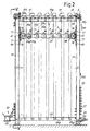
- Fig. 2 shows a side view of the storage unit, generically indicated with 5.
- the cores A produced substantially continuously by the core machines 9, 11, 13, are transported to a chute 23. From here, through gravity, the cores roll to the feed area of the storage unit 5.
- the storage unit 5 comprises a fixed structure 53, carrying a first series of toothed chain wheels 59A in the upper area and a second series of toothed chain wheels 59B in the lower area.
- the axles of the chain wheels 59A and 59B of the two series are fixed in respect of the structure 53 of the storage unit.
- Chains 55 are driven around the toothed wheels.
- the storage unit has two continuous flexible members constituted by chains 55, lying more or less on the same number of vertical planes parallel to each other and defining substantially equal closed paths.
- a single chain 55 and a single path are shown in Fig. 2, it being apparent that the other chain overlaps the one visible in the drawing.
- respective toothed wheels which define the closed paths of the two chains are provided.
- the single chain 55, the relative driving wheels and the closed path along which it extends will be described.
- the storage unit may also have more than two chains or other flexible members parallel to one another, especially when this is required by the length of the products to be handled.
- each chain 55 is defined, as well as by the upper and lower toothed wheels 59A and 59B with fixed axles, carried by the fixed structure 53, also by a first series of toothed chain wheels with moving axle 63A and by a second series of toothed chain wheels with moving axle 63B.
- the toothed wheels with moving axle 63A, 63B are supported by a moving unit or carriage 65 sliding vertically according to the double arrow f65 and guided along vertically extending racks 66, integral with the fixed structure 53, which mesh with pinions 67 carried by the unit 65.
- pinions 67 carried by the unit 65.
- Opposed and coaxial pinions are keyed onto a common shaft 68.
- the arrangement of the racks 66 and pinions 67 with respective shafts allows the moving unit 65 always to translate parallel to itself without tilting.
- lateral guide rollers 77, 78 are provided on corresponding vertical guides.
- the wheels with moving axle of the two series of toothed wheels 63A, 63B are disposed coaxially, so that a toothed wheel 63B of the second series is always coaxial with each toothed wheel of the first series 63A (see Fig.4).
- the driving wheels 63A and 63B with moving axle are coaxial in as much as for each pair of wheels 63A, 63B, the wheel that drives the corresponding branch of the chain 55 coming from the driving wheel 59A with fixed upper axle (indicated with 63A) and the wheel that drives the branch of the chain 55 coming from the respective driving wheel 59B with fixed lower axle are keyed on a single hub 73 supported idle by a corresponding shaft 75 in turn carried projectingly by a beam which is a part of the carriage or moving unit 65 (see Fig.4).
- Supports 57 are integral with each chain 55. Each of these is rigidly fixed to a respective link of the chain 55, as shall be better described with reference to Fig.4. As is visible in Fig. 2, the supports 57 all project from the same side of the chain with which they are integral. More specifically, they extend in a substantially parallel direction to the plane on which the chain 55 to which they are secured lies, that is parallel to the plane of the figure.
- the supports 57 have two opposed and symmetrical V-shaped resting surfaces, indicated with 57V in Fig.3. As shall be more apparent from the description of the operating method of the storage unit, thanks to this layout the supports 57 can receive and support the cores A on one or other of the two opposed V-shaped surfaces, so that in the passage around the upper driving wheels 59A the cores A can pass from a support 57 to the support downstream (in respect of the movement of the chain 55, indicated by the arrow f55). Transfer from a surface 57V to an opposed surface 57V (although of another support) also occurs in proximity to the driving wheels 63A, as shall be described in greater detail hereunder.
- each support 57 is constituted by a laminar component secured to a respective link of the chain 55 and bent in 57X and 57Y so that the resting surfaces 57V are on planes parallel to the median plane of the driving wheels 63A, 63B, but distanced from the wheels so as not to interfere with them.
- the path of the chain 55 and the arrangement of the supports 57 secured to it are such that around the upper driving wheels with fixed axle 59A the supports 57 are located on the outside of the path, that is they extend radially away from the axle of the toothed driving wheels 59A, so as not to interfere with these wheels 59A.
- This is also the case in the stretch of the path of the chain around the lower toothed wheels with fixed axle of the second series 59B.
- a respective guiding surface 61 extends around each of the toothed wheels 59A. This guiding surface 61 prevents the cores A from falling when the supports 57 on which they are resting move around the axle of the wheel 59A.
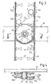
- the arrangement of the chain 55 and of the supports 57 is such that in the driving area around the driving wheels with moving axles of the first and of the second series 63A and 63B, the supports 57 are facing radially inwardly, that is towards the axis of the respective wheel 63A, 63B and are therefore positioned at the side of the plane on which the wheels lie, as can be seen in particular in Figs.3 and 4.
- each transfer member 71 receives the cores A resting on the supports 57 positioned on the branch 55A (see in particular Fig.3) of the chain 55 upstream of the respective driving wheel 63A and transfers them to the supports 57 positioned on the branch 55B of the chain 55 downstream of the driving wheel 63A in respect of the direction of feed f55 of the chain along the path.
- the tubular cores A pass from the descending branch 55A to the ascending branch 55B tangent to each toothed driving wheel 63A, by-passing the wheel.
- the transfer member 71 comprises a transfer surface 71A intersecting the trajectory of the supports 57 carried by the branches upstream and downstream (55A, 55B) of the driving wheel 63A, and inclined from the top downwards and from the branch upstream 55A towards the branch downstream 55B to cause transfer of the tubular cores A through gravity.
- each support 57 deposits the core A on the surface 71A. Due to the inclination of the surface 71A, each core rolls to the other branch 55B of the chain. Here it finds another support 57 that picks it up and conveys it to the subsequent driving wheel with moving axle 63A.
- the supports 57 travel the circumference of the wheels 63A without the cores, as they deposit the cores on the transfer member upstream of the wheel and pick them up again once they are downstream of the wheel.
- the diameter of the driving wheels 63A, 63B and the longitudinal dimension of the supports 57 allow the supports 57 to move around the supporting hub of the driving wheels without knocking against it.
- Fig. 4 shows that the pair of wheels with moving axle 63A, 63B coaxial to each other are supported by a single hub 73, mounted rotatingly on the shaft 75 carried by the moving unit 65, and that this hub has, in an intermediate axial position between the two wheels 63A, 63B keyed on it, an annular groove 79 to increase the space available for the supports 57.
- the transfer members 71 which may be constituted by simple appropriately cut lengths of sheet metal, may advantageously be adjustable in position in respect of the axle of the respective wheels 63A, so that each core A reaches the respective branch 55B of the chain more or less at the moment in which a support 57 integral with the branch 55B transits in front of the surface 71A of the transfer member. This prevents the core from resting on the chain 55 or in any case reduces the contact time with the chain. A sufficiently limited distance between the lower end of the surface 71A and the branch 55B of the chain ensures that the core A does not come into contact with the underlying wheel 63A or 63B.
- the cores A picked up from the chute 23 rotate around the axle of the first driving wheel with fixed axle 59A, that is around the top right wheel in Fig.2.
- the path of the cores then continues until it intercepts the transfer member 71 associated with the first of the driving wheels with moving axle 63A. Thanks to the operation described hereinbefore, before the cores interfere with this wheel they are transferred by the transfer member 71 by-passing the wheel 63A (and the wheel 63B coaxial to it) to the branch 55B of the chain 55 downstream of this wheel.
- each single core is intercepted in an unloading station 83 by a chute 84, formed of two or more inclined section bars, which cause it to drop onto the conveyor 45 (Figs. 1 and 2).
- each chain 55 which extends between the lower driving wheels with fixed axle 59B and the driving wheels with moving axle 63B, has no tubular cores A, and the various supports 57 are thus empty when they reach the lower end of the first ascending stretch of the chain, in front of the chute 23.
- the storage unit thus acts as a FIFO (First In - First Out) unit in the sense that the first core A to be loaded into the storage unit is also the first to be unloaded.
- FIFO First In - First Out
- Movement is imparted to the chains 55 by a pair of motors 101 and 103 disposed on the upper part of the fixed structure 53, which cause the chains to move individually respectively in the feed area and in the unloading area of the cores.
- This makes it possible, in a per se known way, for a different number of cores A to be fed to the inlet than the number of cores unloaded at the outlet during the unit of time.
- the excess is stored in the storage unit if the feed flow rate is above the delivery flow rate. In the opposite case, the shortage in flow will be supplied by the material stored in the storage unit, with consequent reduction in the number of cores contained in the storage unit.
- Modulation of the speed of the first ascending branch of the chain makes it possible to slow down or stop the chain in front of the chute 23 when the number of cores per unit of time reaching it is limited or the flow of cores coming from the core machines actually stops. This guarantees that all the supports 57 located in the stretch of path from the feed station to the delivery station are filled with the respective tubular cores A, to obtain a regular flow of product being delivered.
- the moving unit 65 maintains the same position. However, if the two flow rates are temporarily different from each other, the moving unit 65 will move. It will move upwards if the quantity of cores delivered during the unit of time is greater than the quantity of cores fed and will move downwards in the opposite case.
- the chains 55 are driven around toothed driving wheels 59A, 59B, 63A, 63B, they are usually subject to vibrations, due to inevitable impacts between the links of the chains and the teeth of the toothed wheels, and to the fact that the chains bend according to polygons whose sides correspond to the single chain links.
- an improved embodiment of the storage unit according to the invention may be provided.
- Guiding sliding blocks are associated under each upper toothed driving wheel 59A with fixed axis (if need be excluding the two end wheels).
- Each sliding block is in contact with two parallel branches of the respective flexible member 55, which are in contact with the corresponding driving wheel.
- the width of the sliding block is slightly greater than the distance said two branches would adopt if they were normally extended between the driving wheel 59A and the corresponding underlying wheels 63 carried by the moving unit 65. They have two lateral sides constituted by a rectilinear edge and by two bevels.
- the flexible member is therefore diverted slightly from its normal rectilinear path passing on one or other of the bevels so that each branch is divaricated in respect of the parallel branch driven by the same driving wheel 59A.
- An analogous situation is obtained for the lower driving wheels 59B.
- the same sliding blocks are also mounted on the moving unit 65.
- two series of sliding blocks are disposed on the unit 65, respectively associated with the branches extending from the wheels 65A towards the wheels 59A and, respectively, from the wheels 65B towards the wheels 59B. In both cases they are disposed between parallel branches in contact with two driving wheels 65A or 65B adjacent to each other and not between branches driven by the same wheel.
- the branches of the flexible members 55 are thus held in a slightly divaricated position adjacent to the driving wheels. This contact and slight forcing on the driving members substantially blocks propagation of vibrations from the driving wheels along the free branches of the flexible members.
Landscapes
- Engineering & Computer Science (AREA)
- Mechanical Engineering (AREA)
- Warehouses Or Storage Devices (AREA)
- Packages (AREA)
- Container Filling Or Packaging Operations (AREA)
Claims (27)
- Speichereinheit zum Bevorraten langgestreckter Gegenstände (A) wie etwa Kartonrohre oder dergleichen, mit wenigstens zwei flexiblen Bauteilen (55), die mit Lagern (57) für die Gegenstände ausgerüstet sind und sich längs entsprechender paralleler Pfade erstrecken und bewegen, welche durch mehrere Antriebsräder (59, 63) definiert sind, wobei die Lager (57) seitlich von dem entsprechenden flexiblen Bauteil vorstehen, dadurch gekennzeichnet, dass in jedem der Pfade in Nachbarschaft zu wenigstens einem Antriebsrad ein Übergabeteil (71) positioniert ist, welches die Gegenstände von den Lagern aufnimmt, die auf einem Zweig (55A) des jeweiligen flexiblen Bauteils auf der Aufstromseite des Antriebsrades lokalisiert sind, und sie auf die Lager überträgt, die auf einem abstromseitig des Antriebsrads bezüglich der Vorschubrichtung der flexiblen Bauteile längs der jeweiligen Pfade befindlichen Zweig (55B) des flexiblen Bauteils überträgt, so dass die Gegenstände einer Spur folgen, die an dem Antriebsrad vorbei führt.
- Speichereinheit nach Anspruch 1, dadurch gekennzeichnet, dass die flexiblen Bauteile (55) zusammenhängend sind und sich längs geschlossener Wege erstrecken.
- Speichereinheit nach Anspruch 1 oder 2, dadurch gekennzeichnet, dass jedes der Lager (57) zwei gegenüber liegende Ruheflächen (57V) aufweist, um die Gegenstände aufzunehmen und auf einer oder beiden zweier Seiten des Lagers zu halten.
- Speichereinheit nach Anspruch 1, 2 oder 3, dadurch gekennzeichnet, dass sämtliche Lager aus der gleichen Seite der jeweiligen flexiblen Komponente (55) vorstehen.
- Speichereinheit nach einem oder mehreren der vorstehenden Ansprüche, dadurch gekennzeichnet, dass die Lager (57) sich wenigstens teilweise ungefähr entsprechend einer Ebene erstrecken, die parallel liegt zu derjenigen Ebene, in welcher das flexible Bauteil liegt.
- Speichereinheit nach Anspruch 5, dadurch gekennzeichnet, dass die Lager aus dem relativen flexiblen Bauteil in einer Richtung vorstehen, so dass sie radial gegen die Achse des Antriebsrades oder der Antriebsräder (59, 63) orientiert sind, die den Übergabeteilen zugeordnet sind.
- Speichereinheit nach einem oder mehreren der vorstehenden Ansprüche, dadurch gekennzeichnet, dass das Übergabeteil eine Transferfläche (71A) aufweist, die die Spur der Lager (57) schneidet, die von den aufstromseitigen und abstromseitigen Zweigen wenigstens eines Antriebsrades getragen sind, und von dem oberen Ende abwärts und von dem aufstromseitigen Zweig zum abstromseitigen Zweig geneigt sind, um die Übergabe der Gegenstände durch Schwerkraft zu bewirken, wobei die Wege sich längs Ebenen erstrecken, die im Wesentlichen vertikal liegen.
- Speichereinheit nach einem oder mehreren der vorstehenden Ansprüche, dadurch gekennzeichnet, dass jeder der geschlossenen Pfade durch wenigstens eine erste und durch eine zweite Reihe von Antriebsrädern mit festen Achsen (59A, 59B), und durch eine erste und eine zweite Reihe von Antriebsrädern mit beweglichen Achsen (63A, 63B) definiert sind, die von einer Bewegungseinheit (65) zwischen der ersten und der zweiten Reihe von Antriebsrädern mit festen Achsen getragen sind und dass ein jeweiliges Übertragungsteil (71), welches von der Bewegungseinheit getragen ist, jedem der Antriebsräder der ersten Reihe von Antriebsrädern mit beweglichen Achsen zugeordnet ist.
- Speichereinheit nach Anspruch 8, dadurch gekennzeichnet, dass jedes Übertragungsteil (71) die Gegenstände von einem Zweig zum anderen des flexiblen Bauteils übertragen, und zwar tangential zum Antriebsrad mit beweglicher Achse (63A), der das Übertragungsteil zugeordnet ist.
- Speichereinheit nach Anspruch 8 oder 9, dadurch gekennzeichnet, dass die Lager auf dem jeweiligen flexiblen Bauteil vorstehend befestigt sind, so dass in demjenigen Bereich, in welchem das flexible Bauteil um die Räder mit beweglichen Achsen angetrieben ist, sie radial zur Achse der Räder orientiert sind.
- Speichereinheit nach Anspruch 8, 9 oder 10, dadurch gekennzeichnet, dass jedes Rad der ersten Reihe von Antriebsrädern mit beweglicher Achse koaxial zu einem entsprechenden Rad der zweiten Reihe von Antriebsrädern mit beweglicher Achse ist.
- Speichereinheit nach einem oder mehreren der vorstehenden Ansprüche, dadurch gekennzeichnet, dass das Übertragungsteil in seiner Position bezüglich des Antriebsrades, dem es zugeordnet ist, einstellbar ist.
- Speichereinheit nach einem oder mehreren der vorstehenden Ansprüche, dadurch gekennzeichnet, dass die Lager durch Laminarkomponenten gebildet sind, die an dem jeweiligen flexiblen Bauteil fest befestigt sind.
- Speichereinheit nach Anspruch 13, dadurch gekennzeichnet, dass jede der Lager ein Ende (57Z) aufweist, das mit dem jeweiligen flexiblen Bauteil verbunden ist und einen Abschnitt aufweist, der Ruheflächen für den Gegenstand bildet, wobei das Lager zwischen dem Ende und den Ruheflächen gebogen ist, um die Ruheflächen von der Ebene, auf welcher das jeweilige flexible Bauteil liegt, zu beabstanden.
- Speichereinheit nach einem oder mehreren der vorstehenden Ansprüche, dadurch gekennzeichnet, dass die flexiblen Bauteile (55) durch Ketten gebildet sind.
- Speichereinheit nach Anspruch 15, dadurch gekennzeichnet, dass jedes der Lager an einem jeweiligen Verbindungsglied des flexiblen Bauteils fest befestigt ist.
- Speichereinheit wenigstens nach Anspruch 10, dadurch gekennzeichnet, dass Paare von koaxialen Rädern mit beweglichen Achsen von einer einzigen Nabe (73) getragen sind, die auf einer Welle (75) drehbar befestigt ist, welche von der Bewegungseinheit (65) getragen ist, und dass die Nabe eine Ringnut (79) in einer axialen Zwischenposition zwischen den beiden von ihr getragenen Rädern aufweist.
- Speichereinheit nach einem oder mehreren der Ansprüche 8 bis 11, dadurch gekennzeichnet, dass die Antriebsräder mit beweglicher Achse einen größeren Radius haben als die Antriebsräder mit fester Achse.
- Speichereinheit nach einem oder mehreren der vorstehenden Ansprüche, dadurch gekennzeichnet, dass ein Trennbalken (61) zur Führung und zum Halten der auf den Lagern ruhenden Gegenstände sich um wenigstens einige der Antriebsräder erstreckt.
- Speichereinheit nach einem oder mehreren der vorstehenden Ansprüche, dadurch gekennzeichnet, dass die flexiblen Bauteile sich längs der jeweiligen Wege stets in der gleichen Richtung bewegen, die Gegenstände von einer Beladestation (81) zu einer Ausgabestation (83) übertragen, wobei die Lager, die längs eines Wegabschnittes zwischen der Ladestation und der Ausgabestation lokalisiert sind, mit den Gegenständen beladen werden und die Lager, die sich längs des Wegteiles von der Ausgabestation zur Ladestation befinden, leer sind.
- Speichereinheit nach einem oder mehreren der vorstehenden Ansprüche, dadurch gekennzeichnet, dass wenigstens ein Führungsgleitblock zwischen wenigstens zwei parallelen Zweigen jedes der flexiblen Bauteile in Kontakt mit den beiden Zweigen angeordnet ist.
- Speichereinheit nach Anspruch 21, dadurch gekennzeichnet, dass der Gleitblock in der Nachbarschaft eines oder mehrerer Antriebsräder (57, 63) angeordnet ist, und zwar in Kontakt mit den parallelen Zweigen des jeweiligen flexiblen Bauteils.
- Speichereinheit nach Anspruch 21 oder 22, dadurch gekennzeichnet, dass die Breite des Gleitblockes größer ist als der Abstand zwischen zwei parallelen Zweigen des flexiblen Bauteils, wobei die Zweige durch den Gleitblock leicht gespreizt werden.
- Speichereinheit nach wenigstens Ansprüchen 8 und 21, dadurch gekennzeichnet, dass ein jeweiliger Führungsgleitblock an den Rädern der ersten und zweiten Reihen von Antriebsrädern mit fester Achse in Kontakt mit den beiden Zweigen des flexiblen Bauteils in Kontakt mit dem jeweiligen Antriebsrad mit fester Achse angeordnet ist.
- Speichereinheit nach wenigstens Anspruch 8 und 21, dadurch gekennzeichnet, dass die Bewegungseinheit (65) jeweilige Führungsgleitblöcke trägt, die zwischen parallelen Zweigen des Antriebsteils zwischen zwei benachbarten Antriebsrädern, die von der Bewegungseinheit getragen sind, angeordnet sind.
- Speichereinheit nach einem oder mehreren der Ansprüche 21 bis 25, dadurch gekennzeichnet, dass die Führungsgleitblöcke mit Fasen versehene Seiten aufweisen.
- Speichereinheit nach Anspruch 26, dadurch gekennzeichnet, dass die Gleitblöcke Seiten mit parallelen geradlinigen Abschnitten zwischen den Fasen aufweisen.
Applications Claiming Priority (5)
| Application Number | Priority Date | Filing Date | Title |
|---|---|---|---|
| ITFI20020130 | 2002-07-18 | ||
| ITFI20020130 ITFI20020130A1 (it) | 2002-07-18 | 2002-07-18 | Dispositivo accumulatore con organi scambiatori per prodotti allungati, come tubi di cartone o simili |
| IT000066A ITFI20030066A1 (it) | 2003-03-13 | 2003-03-13 | Dispositivo accumulatore a catene per prodotti e mezzi |
| ITFI20030066 | 2003-03-13 | ||
| PCT/IT2003/000423 WO2004009479A1 (en) | 2002-07-18 | 2003-07-04 | Storage unit for elongated products |
Publications (2)
| Publication Number | Publication Date |
|---|---|
| EP1532062A1 EP1532062A1 (de) | 2005-05-25 |
| EP1532062B1 true EP1532062B1 (de) | 2006-09-06 |
Family
ID=30772082
Family Applications (1)
| Application Number | Title | Priority Date | Filing Date |
|---|---|---|---|
| EP03741097A Expired - Lifetime EP1532062B1 (de) | 2002-07-18 | 2003-07-04 | Speichereinheit für längliche produkte |
Country Status (9)
| Country | Link |
|---|---|
| US (1) | US7258221B2 (de) |
| EP (1) | EP1532062B1 (de) |
| AT (1) | ATE338713T1 (de) |
| AU (1) | AU2003281528A1 (de) |
| BR (1) | BR0312767A (de) |
| CA (1) | CA2492232A1 (de) |
| DE (1) | DE60308196T2 (de) |
| ES (1) | ES2271610T3 (de) |
| WO (1) | WO2004009479A1 (de) |
Families Citing this family (11)
| Publication number | Priority date | Publication date | Assignee | Title |
|---|---|---|---|---|
| ITFI20030066A1 (it) * | 2003-03-13 | 2004-09-14 | Perini Fabio Spa | Dispositivo accumulatore a catene per prodotti e mezzi |
| BR112012004777A2 (pt) | 2009-09-03 | 2019-09-24 | Genentech Inc | métodos para tratar diagnósticar e monitorar artrite reumatoide |
| IT1397711B1 (it) | 2010-01-22 | 2013-01-24 | Perini Fabio Spa | Polmone di accumulo per anime tubolari di avvolgimento. |
| EP3409289B1 (de) | 2010-02-26 | 2020-09-30 | Novo Nordisk A/S | Stabile, antikörperhaltige zusammensetzungen |
| RU2012153786A (ru) | 2010-05-28 | 2014-07-10 | Ново Нордиск А/С | Стабильные многодозовые композиции, содержащие антитело и консервант |
| US8490772B2 (en) | 2010-12-28 | 2013-07-23 | C. G. Bretting Manufacturing Co., Inc. | High speed interfolded log accumulator |
| WO2012118750A2 (en) | 2011-02-28 | 2012-09-07 | Genentech, Inc. | Biological markers and methods for predicting response to b-cell antagonists |
| CN105916785B (zh) * | 2014-02-24 | 2019-04-30 | 未来股份公司 | 用于硬纸管的存储单元和用于存储硬纸管的方法 |
| ITUB20152457A1 (it) * | 2015-07-24 | 2017-01-24 | Elisabetta Tessari | Magazzino accumulatore temporaneo di prodotti allungati, in particolare tubolari |
| US11297777B2 (en) * | 2018-05-01 | 2022-04-12 | John H. Oberthier | Apparatus and methods for growing organic matter |
| CN109512020B (zh) * | 2018-11-17 | 2021-12-03 | 昆明鼎承科技有限公司 | 容积可调的棒状物先进先出箱式存储装置 |
Family Cites Families (16)
| Publication number | Priority date | Publication date | Assignee | Title |
|---|---|---|---|---|
| US3643787A (en) * | 1969-02-20 | 1972-02-22 | Mather & Platt Ltd | Sterilizing machines |
| CH670243A5 (de) * | 1986-07-08 | 1989-05-31 | Ciba Geigy Ag | |
| US4995769A (en) * | 1988-04-05 | 1991-02-26 | Fabriques De Tabac Reunies, S.A. | Rod conveyor and compartment therefor |
| DE3824230A1 (de) * | 1988-07-16 | 1990-01-25 | Spiess Gmbh G | Vorrichtung zum transport von werkstuecken |
| DE9012074U1 (de) * | 1990-06-06 | 1990-12-13 | Rotzinger Ag, Kaiseraugst | Kettenspeicher |
| AT396539B (de) * | 1991-07-25 | 1993-10-25 | Haas Franz Waffelmasch | Waffelblockmagazin zum kurzzeitigen zwischenlagern von waffelblöcken |
| IT1260039B (it) * | 1992-02-24 | 1996-03-28 | Metodo di transito per piccoli oggetti all'interno di camere di trattamento, e suoi mezzi attuatori | |
| ES2068753B1 (es) * | 1993-04-14 | 1998-01-16 | Technological Research Co Ltd | Maquina perfeccionada para el ordenado de tubos textiles, para maquinas continuas de hilar. |
| US5873806A (en) | 1993-10-08 | 1999-02-23 | Fabio Perini, S.P.A. | Machine for producing cardboard or similar tubes, with means for cutting the tube into sections of predetermined lengths |
| FR2719566B1 (fr) * | 1994-05-03 | 1996-07-19 | Sapal Plieuses Automatiques | Installation de stockage pendulaire. |
| IT1278648B1 (it) | 1995-04-21 | 1997-11-27 | Perini Fabio Spa | Polmone per l'accumulo di semilavorati, con mezzi di regolazione della velocita' di avanzamento |
| IT1303054B1 (it) * | 1998-04-30 | 2000-10-23 | Carle & Montanari Spa | Accumulatore per stampi |
| ITFI20010121A1 (it) * | 2001-06-29 | 2002-12-29 | Perini Fabio Spa | Polmone di accumulo per prodotti allungati,come tubi od altro |
| DE50207851D1 (de) * | 2002-06-11 | 2006-09-28 | Rotzinger Ag | Kettenspeicher sowie Verfahren zu dessen Steuerung |
| ITBO20020389A1 (it) * | 2002-06-18 | 2003-12-18 | Gd Spa | Unita a magazzino per prodotti di forma sostanzialmente parallelepipeda |
| DE50205746D1 (de) * | 2002-06-25 | 2006-04-13 | Rotzinger Ag Kaiseraugst | Kettenspeicher sowie Verfahren zum Beladen des Speichers |
-
2003
- 2003-07-04 BR BR0312767-2A patent/BR0312767A/pt active Search and Examination
- 2003-07-04 DE DE60308196T patent/DE60308196T2/de not_active Expired - Lifetime
- 2003-07-04 WO PCT/IT2003/000423 patent/WO2004009479A1/en not_active Ceased
- 2003-07-04 AU AU2003281528A patent/AU2003281528A1/en not_active Abandoned
- 2003-07-04 EP EP03741097A patent/EP1532062B1/de not_active Expired - Lifetime
- 2003-07-04 ES ES03741097T patent/ES2271610T3/es not_active Expired - Lifetime
- 2003-07-04 US US10/520,895 patent/US7258221B2/en not_active Expired - Fee Related
- 2003-07-04 CA CA002492232A patent/CA2492232A1/en not_active Abandoned
- 2003-07-04 AT AT03741097T patent/ATE338713T1/de not_active IP Right Cessation
Also Published As
| Publication number | Publication date |
|---|---|
| WO2004009479A1 (en) | 2004-01-29 |
| ATE338713T1 (de) | 2006-09-15 |
| US7258221B2 (en) | 2007-08-21 |
| DE60308196D1 (de) | 2006-10-19 |
| ES2271610T3 (es) | 2007-04-16 |
| EP1532062A1 (de) | 2005-05-25 |
| AU2003281528A1 (en) | 2004-02-09 |
| BR0312767A (pt) | 2005-05-03 |
| US20050173228A1 (en) | 2005-08-11 |
| DE60308196T2 (de) | 2007-08-02 |
| CA2492232A1 (en) | 2004-01-29 |
Similar Documents
| Publication | Publication Date | Title |
|---|---|---|
| CA1071663A (en) | Apparatus for storing articles discharged at a high rate from production machines | |
| US5255773A (en) | Accumulator for conveyor system | |
| JP3974409B2 (ja) | 搬送装置及びそれを備えた箱詰め装置 | |
| US7258221B2 (en) | Storage unit for elongated products | |
| EP2526037B1 (de) | Speichereinheit für röhrenförmige wickelkerne | |
| ITFI950075A1 (it) | Polmone per l'accumulo di semilavorati,con mezzi di regolazione della velocita' di avanzamento | |
| EP1436219B1 (de) | Stauförderer für längliche produkte, wie rohre und ähnliches | |
| EP1845039B1 (de) | Dynamische Vorrichtung zur vorübergehenden Lagerung von Artikeln, wie etwa Spritzen | |
| JP2004161494A (ja) | 小包体搬送組体 | |
| JPH08504730A (ja) | ローディング・ステーションからアンローディング・ステーションに搬送される間にほぼ螺旋状のラインに沿って製品ユニットの向きを変える積重ね装置及び積重ね方法 | |
| JPH0343323A (ja) | ティッシュペーパーの小型パックのグループのハンドル形態をなす大型ユニット製品の製造装置 | |
| US20060052196A1 (en) | Chain storage unit for products and means to reduce chanin vibrations | |
| US5873450A (en) | Apparatus and method for up-ending workpieces | |
| SK279527B6 (sk) | Spôsob prepravy výrobkov a zariadenie na vykonávan | |
| US4986409A (en) | Assembly and method for stacking articles | |
| CA1107632A (en) | Package forming machine | |
| US5092452A (en) | Cheese stocker | |
| US5176245A (en) | Conveyor device for transporting peg trays | |
| JPH07304121A (ja) | ブランクを保管する方法及び装置 | |
| MX2015006166A (es) | Metodo y sistema para transportar productos absorbentes enrollados. | |
| JPH11199040A (ja) | 容器類の搬送装置 | |
| JP2004168491A (ja) | 物品搬送装置及びそれを備えた箱詰め装置 | |
| GB2091198A (en) | Buffer storage apparatus | |
| JPH07125892A (ja) | ラップ巻取機における原反紙管供給装置 | |
| JP3691232B2 (ja) | 農産物の移送供給装置 |
Legal Events
| Date | Code | Title | Description |
|---|---|---|---|
| PUAI | Public reference made under article 153(3) epc to a published international application that has entered the european phase |
Free format text: ORIGINAL CODE: 0009012 |
|
| 17P | Request for examination filed |
Effective date: 20050114 |
|
| AK | Designated contracting states |
Kind code of ref document: A1 Designated state(s): AT BE BG CH CY CZ DE DK EE ES FI FR GB GR HU IE IT LI LU MC NL PT RO SE SI SK TR |
|
| AX | Request for extension of the european patent |
Extension state: AL LT LV MK |
|
| DAX | Request for extension of the european patent (deleted) | ||
| GRAP | Despatch of communication of intention to grant a patent |
Free format text: ORIGINAL CODE: EPIDOSNIGR1 |
|
| GRAS | Grant fee paid |
Free format text: ORIGINAL CODE: EPIDOSNIGR3 |
|
| GRAA | (expected) grant |
Free format text: ORIGINAL CODE: 0009210 |
|
| AK | Designated contracting states |
Kind code of ref document: B1 Designated state(s): AT BE BG CH CY CZ DE DK EE ES FI FR GB GR HU IE IT LI LU MC NL PT RO SE SI SK TR |
|
| PG25 | Lapsed in a contracting state [announced via postgrant information from national office to epo] |
Ref country code: IT Free format text: LAPSE BECAUSE OF FAILURE TO SUBMIT A TRANSLATION OF THE DESCRIPTION OR TO PAY THE FEE WITHIN THE PRESCRIBED TIME-LIMIT;WARNING: LAPSES OF ITALIAN PATENTS WITH EFFECTIVE DATE BEFORE 2007 MAY HAVE OCCURRED AT ANY TIME BEFORE 2007. THE CORRECT EFFECTIVE DATE MAY BE DIFFERENT FROM THE ONE RECORDED. Effective date: 20060906 Ref country code: CZ Free format text: LAPSE BECAUSE OF FAILURE TO SUBMIT A TRANSLATION OF THE DESCRIPTION OR TO PAY THE FEE WITHIN THE PRESCRIBED TIME-LIMIT Effective date: 20060906 Ref country code: CH Free format text: LAPSE BECAUSE OF FAILURE TO SUBMIT A TRANSLATION OF THE DESCRIPTION OR TO PAY THE FEE WITHIN THE PRESCRIBED TIME-LIMIT Effective date: 20060906 Ref country code: NL Free format text: LAPSE BECAUSE OF FAILURE TO SUBMIT A TRANSLATION OF THE DESCRIPTION OR TO PAY THE FEE WITHIN THE PRESCRIBED TIME-LIMIT Effective date: 20060906 Ref country code: FI Free format text: LAPSE BECAUSE OF FAILURE TO SUBMIT A TRANSLATION OF THE DESCRIPTION OR TO PAY THE FEE WITHIN THE PRESCRIBED TIME-LIMIT Effective date: 20060906 Ref country code: LI Free format text: LAPSE BECAUSE OF FAILURE TO SUBMIT A TRANSLATION OF THE DESCRIPTION OR TO PAY THE FEE WITHIN THE PRESCRIBED TIME-LIMIT Effective date: 20060906 Ref country code: AT Free format text: LAPSE BECAUSE OF FAILURE TO SUBMIT A TRANSLATION OF THE DESCRIPTION OR TO PAY THE FEE WITHIN THE PRESCRIBED TIME-LIMIT Effective date: 20060906 Ref country code: SK Free format text: LAPSE BECAUSE OF FAILURE TO SUBMIT A TRANSLATION OF THE DESCRIPTION OR TO PAY THE FEE WITHIN THE PRESCRIBED TIME-LIMIT Effective date: 20060906 Ref country code: BE Free format text: LAPSE BECAUSE OF FAILURE TO SUBMIT A TRANSLATION OF THE DESCRIPTION OR TO PAY THE FEE WITHIN THE PRESCRIBED TIME-LIMIT Effective date: 20060906 Ref country code: RO Free format text: LAPSE BECAUSE OF FAILURE TO SUBMIT A TRANSLATION OF THE DESCRIPTION OR TO PAY THE FEE WITHIN THE PRESCRIBED TIME-LIMIT Effective date: 20060906 Ref country code: SI Free format text: LAPSE BECAUSE OF FAILURE TO SUBMIT A TRANSLATION OF THE DESCRIPTION OR TO PAY THE FEE WITHIN THE PRESCRIBED TIME-LIMIT Effective date: 20060906 |
|
| REG | Reference to a national code |
Ref country code: GB Ref legal event code: FG4D |
|
| REG | Reference to a national code |
Ref country code: CH Ref legal event code: EP |
|
| REG | Reference to a national code |
Ref country code: IE Ref legal event code: FG4D |
|
| REF | Corresponds to: |
Ref document number: 60308196 Country of ref document: DE Date of ref document: 20061019 Kind code of ref document: P |
|
| PG25 | Lapsed in a contracting state [announced via postgrant information from national office to epo] |
Ref country code: SE Free format text: LAPSE BECAUSE OF FAILURE TO SUBMIT A TRANSLATION OF THE DESCRIPTION OR TO PAY THE FEE WITHIN THE PRESCRIBED TIME-LIMIT Effective date: 20061206 Ref country code: DK Free format text: LAPSE BECAUSE OF FAILURE TO SUBMIT A TRANSLATION OF THE DESCRIPTION OR TO PAY THE FEE WITHIN THE PRESCRIBED TIME-LIMIT Effective date: 20061206 Ref country code: BG Free format text: LAPSE BECAUSE OF FAILURE TO SUBMIT A TRANSLATION OF THE DESCRIPTION OR TO PAY THE FEE WITHIN THE PRESCRIBED TIME-LIMIT Effective date: 20061206 |
|
| PG25 | Lapsed in a contracting state [announced via postgrant information from national office to epo] |
Ref country code: PT Free format text: LAPSE BECAUSE OF FAILURE TO SUBMIT A TRANSLATION OF THE DESCRIPTION OR TO PAY THE FEE WITHIN THE PRESCRIBED TIME-LIMIT Effective date: 20070219 |
|
| NLV1 | Nl: lapsed or annulled due to failure to fulfill the requirements of art. 29p and 29m of the patents act | ||
| REG | Reference to a national code |
Ref country code: CH Ref legal event code: PL |
|
| ET | Fr: translation filed | ||
| REG | Reference to a national code |
Ref country code: ES Ref legal event code: FG2A Ref document number: 2271610 Country of ref document: ES Kind code of ref document: T3 |
|
| PGFP | Annual fee paid to national office [announced via postgrant information from national office to epo] |
Ref country code: ES Payment date: 20070614 Year of fee payment: 5 |
|
| PLBE | No opposition filed within time limit |
Free format text: ORIGINAL CODE: 0009261 |
|
| STAA | Information on the status of an ep patent application or granted ep patent |
Free format text: STATUS: NO OPPOSITION FILED WITHIN TIME LIMIT |
|
| 26N | No opposition filed |
Effective date: 20070607 |
|
| PG25 | Lapsed in a contracting state [announced via postgrant information from national office to epo] |
Ref country code: MC Free format text: LAPSE BECAUSE OF NON-PAYMENT OF DUE FEES Effective date: 20070731 Ref country code: GR Free format text: LAPSE BECAUSE OF FAILURE TO SUBMIT A TRANSLATION OF THE DESCRIPTION OR TO PAY THE FEE WITHIN THE PRESCRIBED TIME-LIMIT Effective date: 20061207 |
|
| PG25 | Lapsed in a contracting state [announced via postgrant information from national office to epo] |
Ref country code: EE Free format text: LAPSE BECAUSE OF FAILURE TO SUBMIT A TRANSLATION OF THE DESCRIPTION OR TO PAY THE FEE WITHIN THE PRESCRIBED TIME-LIMIT Effective date: 20060906 |
|
| PG25 | Lapsed in a contracting state [announced via postgrant information from national office to epo] |
Ref country code: IE Free format text: LAPSE BECAUSE OF NON-PAYMENT OF DUE FEES Effective date: 20070704 |
|
| PGFP | Annual fee paid to national office [announced via postgrant information from national office to epo] |
Ref country code: FR Payment date: 20080716 Year of fee payment: 6 |
|
| PG25 | Lapsed in a contracting state [announced via postgrant information from national office to epo] |
Ref country code: CY Free format text: LAPSE BECAUSE OF FAILURE TO SUBMIT A TRANSLATION OF THE DESCRIPTION OR TO PAY THE FEE WITHIN THE PRESCRIBED TIME-LIMIT Effective date: 20060906 Ref country code: LU Free format text: LAPSE BECAUSE OF NON-PAYMENT OF DUE FEES Effective date: 20070704 |
|
| REG | Reference to a national code |
Ref country code: ES Ref legal event code: FD2A Effective date: 20080705 |
|
| PG25 | Lapsed in a contracting state [announced via postgrant information from national office to epo] |
Ref country code: HU Free format text: LAPSE BECAUSE OF FAILURE TO SUBMIT A TRANSLATION OF THE DESCRIPTION OR TO PAY THE FEE WITHIN THE PRESCRIBED TIME-LIMIT Effective date: 20070307 Ref country code: TR Free format text: LAPSE BECAUSE OF FAILURE TO SUBMIT A TRANSLATION OF THE DESCRIPTION OR TO PAY THE FEE WITHIN THE PRESCRIBED TIME-LIMIT Effective date: 20060906 |
|
| PG25 | Lapsed in a contracting state [announced via postgrant information from national office to epo] |
Ref country code: ES Free format text: LAPSE BECAUSE OF NON-PAYMENT OF DUE FEES Effective date: 20080705 |
|
| REG | Reference to a national code |
Ref country code: FR Ref legal event code: ST Effective date: 20100331 |
|
| PG25 | Lapsed in a contracting state [announced via postgrant information from national office to epo] |
Ref country code: FR Free format text: LAPSE BECAUSE OF NON-PAYMENT OF DUE FEES Effective date: 20090731 |
|
| PGFP | Annual fee paid to national office [announced via postgrant information from national office to epo] |
Ref country code: GB Payment date: 20110629 Year of fee payment: 9 |
|
| PGFP | Annual fee paid to national office [announced via postgrant information from national office to epo] |
Ref country code: DE Payment date: 20110706 Year of fee payment: 9 |
|
| GBPC | Gb: european patent ceased through non-payment of renewal fee |
Effective date: 20120704 |
|
| PG25 | Lapsed in a contracting state [announced via postgrant information from national office to epo] |
Ref country code: DE Free format text: LAPSE BECAUSE OF NON-PAYMENT OF DUE FEES Effective date: 20130201 Ref country code: GB Free format text: LAPSE BECAUSE OF NON-PAYMENT OF DUE FEES Effective date: 20120704 |
|
| REG | Reference to a national code |
Ref country code: DE Ref legal event code: R119 Ref document number: 60308196 Country of ref document: DE Effective date: 20130201 |