EP1532068B1 - Dispositif permettant de monter des housses de siege - Google Patents
Dispositif permettant de monter des housses de siege Download PDFInfo
- Publication number
- EP1532068B1 EP1532068B1 EP03792159A EP03792159A EP1532068B1 EP 1532068 B1 EP1532068 B1 EP 1532068B1 EP 03792159 A EP03792159 A EP 03792159A EP 03792159 A EP03792159 A EP 03792159A EP 1532068 B1 EP1532068 B1 EP 1532068B1
- Authority
- EP
- European Patent Office
- Prior art keywords
- seat
- gripping elements
- foam cushion
- positioning device
- gripping
- Prior art date
- Legal status (The legal status is an assumption and is not a legal conclusion. Google has not performed a legal analysis and makes no representation as to the accuracy of the status listed.)
- Expired - Lifetime
Links
- 239000006260 foam Substances 0.000 claims abstract description 43
- 238000000034 method Methods 0.000 description 5
- 239000004744 fabric Substances 0.000 description 3
- 238000003780 insertion Methods 0.000 description 2
- 230000037431 insertion Effects 0.000 description 2
- 239000010985 leather Substances 0.000 description 2
- 239000000463 material Substances 0.000 description 2
- 238000000465 moulding Methods 0.000 description 2
- 230000002093 peripheral effect Effects 0.000 description 2
- 239000004033 plastic Substances 0.000 description 2
- 229920003023 plastic Polymers 0.000 description 2
- 241000226585 Antennaria plantaginifolia Species 0.000 description 1
- 229920005830 Polyurethane Foam Polymers 0.000 description 1
- 244000309466 calf Species 0.000 description 1
- 239000011248 coating agent Substances 0.000 description 1
- 238000000576 coating method Methods 0.000 description 1
- 230000001419 dependent effect Effects 0.000 description 1
- 238000010586 diagram Methods 0.000 description 1
- 230000000694 effects Effects 0.000 description 1
- 238000005516 engineering process Methods 0.000 description 1
- 238000001125 extrusion Methods 0.000 description 1
- 239000006261 foam material Substances 0.000 description 1
- 238000009434 installation Methods 0.000 description 1
- 239000011496 polyurethane foam Substances 0.000 description 1
- 230000002441 reversible effect Effects 0.000 description 1
- 238000009958 sewing Methods 0.000 description 1
Images


Classifications
-
- B—PERFORMING OPERATIONS; TRANSPORTING
- B68—SADDLERY; UPHOLSTERY
- B68G—METHODS, EQUIPMENT, OR MACHINES FOR USE IN UPHOLSTERING; UPHOLSTERY NOT OTHERWISE PROVIDED FOR
- B68G7/00—Making upholstery
- B68G7/05—Covering or enveloping cores of pads
-
- B—PERFORMING OPERATIONS; TRANSPORTING
- B29—WORKING OF PLASTICS; WORKING OF SUBSTANCES IN A PLASTIC STATE IN GENERAL
- B29C—SHAPING OR JOINING OF PLASTICS; SHAPING OF MATERIAL IN A PLASTIC STATE, NOT OTHERWISE PROVIDED FOR; AFTER-TREATMENT OF THE SHAPED PRODUCTS, e.g. REPAIRING
- B29C63/00—Lining or sheathing, i.e. applying preformed layers or sheathings of plastics; Apparatus therefor
- B29C63/02—Lining or sheathing, i.e. applying preformed layers or sheathings of plastics; Apparatus therefor using sheet or web-like material
-
- Y—GENERAL TAGGING OF NEW TECHNOLOGICAL DEVELOPMENTS; GENERAL TAGGING OF CROSS-SECTIONAL TECHNOLOGIES SPANNING OVER SEVERAL SECTIONS OF THE IPC; TECHNICAL SUBJECTS COVERED BY FORMER USPC CROSS-REFERENCE ART COLLECTIONS [XRACs] AND DIGESTS
- Y10—TECHNICAL SUBJECTS COVERED BY FORMER USPC
- Y10T—TECHNICAL SUBJECTS COVERED BY FORMER US CLASSIFICATION
- Y10T29/00—Metal working
- Y10T29/48—Upholstered article making
-
- Y—GENERAL TAGGING OF NEW TECHNOLOGICAL DEVELOPMENTS; GENERAL TAGGING OF CROSS-SECTIONAL TECHNOLOGIES SPANNING OVER SEVERAL SECTIONS OF THE IPC; TECHNICAL SUBJECTS COVERED BY FORMER USPC CROSS-REFERENCE ART COLLECTIONS [XRACs] AND DIGESTS
- Y10—TECHNICAL SUBJECTS COVERED BY FORMER USPC
- Y10T—TECHNICAL SUBJECTS COVERED BY FORMER US CLASSIFICATION
- Y10T29/00—Metal working
- Y10T29/48—Upholstered article making
- Y10T29/486—Cover stretching
-
- Y—GENERAL TAGGING OF NEW TECHNOLOGICAL DEVELOPMENTS; GENERAL TAGGING OF CROSS-SECTIONAL TECHNOLOGIES SPANNING OVER SEVERAL SECTIONS OF THE IPC; TECHNICAL SUBJECTS COVERED BY FORMER USPC CROSS-REFERENCE ART COLLECTIONS [XRACs] AND DIGESTS
- Y10—TECHNICAL SUBJECTS COVERED BY FORMER USPC
- Y10T—TECHNICAL SUBJECTS COVERED BY FORMER US CLASSIFICATION
- Y10T29/00—Metal working
- Y10T29/48—Upholstered article making
- Y10T29/488—Upholstered article making form or holder
-
- Y—GENERAL TAGGING OF NEW TECHNOLOGICAL DEVELOPMENTS; GENERAL TAGGING OF CROSS-SECTIONAL TECHNOLOGIES SPANNING OVER SEVERAL SECTIONS OF THE IPC; TECHNICAL SUBJECTS COVERED BY FORMER USPC CROSS-REFERENCE ART COLLECTIONS [XRACs] AND DIGESTS
- Y10—TECHNICAL SUBJECTS COVERED BY FORMER USPC
- Y10T—TECHNICAL SUBJECTS COVERED BY FORMER US CLASSIFICATION
- Y10T29/00—Metal working
- Y10T29/49—Method of mechanical manufacture
- Y10T29/49826—Assembling or joining
- Y10T29/49895—Associating parts by use of aligning means [e.g., use of a drift pin or a "fixture"]
-
- Y—GENERAL TAGGING OF NEW TECHNOLOGICAL DEVELOPMENTS; GENERAL TAGGING OF CROSS-SECTIONAL TECHNOLOGIES SPANNING OVER SEVERAL SECTIONS OF THE IPC; TECHNICAL SUBJECTS COVERED BY FORMER USPC CROSS-REFERENCE ART COLLECTIONS [XRACs] AND DIGESTS
- Y10—TECHNICAL SUBJECTS COVERED BY FORMER USPC
- Y10T—TECHNICAL SUBJECTS COVERED BY FORMER US CLASSIFICATION
- Y10T29/00—Metal working
- Y10T29/53—Means to assemble or disassemble
- Y10T29/53039—Means to assemble or disassemble with control means energized in response to activator stimulated by condition sensor
- Y10T29/53061—Responsive to work or work-related machine element
-
- Y—GENERAL TAGGING OF NEW TECHNOLOGICAL DEVELOPMENTS; GENERAL TAGGING OF CROSS-SECTIONAL TECHNOLOGIES SPANNING OVER SEVERAL SECTIONS OF THE IPC; TECHNICAL SUBJECTS COVERED BY FORMER USPC CROSS-REFERENCE ART COLLECTIONS [XRACs] AND DIGESTS
- Y10—TECHNICAL SUBJECTS COVERED BY FORMER USPC
- Y10T—TECHNICAL SUBJECTS COVERED BY FORMER US CLASSIFICATION
- Y10T29/00—Metal working
- Y10T29/53—Means to assemble or disassemble
- Y10T29/53961—Means to assemble or disassemble with work-holder for assembly
-
- Y—GENERAL TAGGING OF NEW TECHNOLOGICAL DEVELOPMENTS; GENERAL TAGGING OF CROSS-SECTIONAL TECHNOLOGIES SPANNING OVER SEVERAL SECTIONS OF THE IPC; TECHNICAL SUBJECTS COVERED BY FORMER USPC CROSS-REFERENCE ART COLLECTIONS [XRACs] AND DIGESTS
- Y10—TECHNICAL SUBJECTS COVERED BY FORMER USPC
- Y10T—TECHNICAL SUBJECTS COVERED BY FORMER US CLASSIFICATION
- Y10T29/00—Metal working
- Y10T29/53—Means to assemble or disassemble
- Y10T29/53978—Means to assemble or disassemble including means to relatively position plural work parts
Definitions
- the invention relates to a device for mounting seat covers of any kind, to foam cushion parts of a seat, in particular vehicle seat according to the feature configuration of the preamble of claim 1.
- the attributable foam cushion parts of the respective seat which are to be obtained, consist of a conventional resilient foam material, such as polyurethane foam and the respective seat part with its foam pad has on its side facing the seat cover channel-shaped recesses, in the example by hand, the respective profile strip for a fixing process of the seat cover on the foam cushion part can be inserted.
- the respective profile used in this way has flank parts on the edge side and the pertinent flank parts engage under the end flanks of the foam cushion part, which delimit a channel-shaped central recess, through which the profile part can be inserted into the pertinent foam channel.
- a major advantage of the pertinent profile fastening systems is that with worn seat covers or foam cushion parts, the pertinent components can be exchanged by disengaging the profile part arranged on the seat cover, with the channel introduced into the foam cushion part.
- the respective insert profile can be produced inexpensively in the manner of an extrusion profile, so that the described fixed solution can be realized inexpensively despite the necessary manual assembly work.
- US 2002/108222 A1 is a generic device for mounting seat covers on foam upholstered parts of a seat known with gripping elements, summarized in groups of actuations serve arranged on the seat cover profile strips and by means of a positioning device that allows a relative movement between the foam cushion part and the respective gripping element, the profile strips in channel-like recesses in the foam cushion part draws to determine the seat cover on the foam cushion part.
- the invention has the object to further improve the known solution to the effect that further time and cost advantages can be obtained.
- a task solves a device with the features of claim 1 in its entirety.
- the device According to the content of the characterizing part of claim 1 is provided in the device according to the invention that all gripping elements are covered by a common frame part of the positioning, which is variable in a linear movement by means of a linear drive in height, that the positioning means a support member for the support the foam cushion part, which is penetrated by the gripping elements in a lowered position and is free in a raised position of the gripping elements, and that for taking the individual positions of the support member is a further linear drive which allows a superimposed movement to the first linear drive.
- the pertinent device essentially an automatic loading operation of the respective profile strip is made possible on the seat cover.
- the moldings which are at the bottom the respective seat cover are sewn, inserted by hand or automatically in the respective receptacles of the gripping elements and held there.
- the pertinent gripping elements pass through in the described setting situation recesses in the foam cushion part, which extend transversely to the mentioned channel-like guides for the respective profile strip.
- the profile strips are set in the respective foam cushion part, wherein the pertinent fixing process is fully automatic.
- the device according to the invention can be specially adapted for special seat parts of the respective seat, for example for the headrest area, the backrest, the actual seat part and optionally for passenger seats in the form of leg, foot or calf pads.
- the device according to the invention is in the Fig. 1 shown in their initial state.
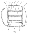
- the pertinent device is used for mounting seat covers of any kind, for example, a pertinent seat cover in the Fig. 6 is shown, from its bottom view.
- Existing seat covers 10 which may consist of a fabric or leather material, and optionally of plastic, are to be determined on foam cushion parts 12 (see, for example Fig. 5 ) so as to obtain a seat part for a vehicle seat or passenger seat.
- Standing seat parts can also be used for treatment chairs, for example in the operating theater or the like.
- the embodiment shown relates directly to the seat part of a motor vehicle seat; However, other seat parts or seat components can be compared in a similar manner, for example headrests, backrests, leg rests, etc.
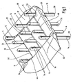
- the device according to the invention has a multiplicity of gripping elements 14, wherein in the present case, twelve gripping elements 14 are in use for drawing a seat part.
- the pertinent twelve gripping elements 14 are arranged in five actuation groups 16, 18, 20, 22 and 24 and summarized in such a way.
- the pertinent gripping elements 14 are used for receiving, arranged on the seat cover profile strips 26, 28, 30, 32 and 34, wherein the pertinent profile strips in the predetermined order the respective groups of actuation of gripping elements 14 are assigned.
- Said profiled strips are fixedly connected to the underside of the seat cover 10 via sewing flags 38 of the usual type and form, with their longitudinal and transverse directions, the corresponding seams 39, 40 on the upper side of the seat part (cf. Fig. 3 ) out.
- the device furthermore has a positioning device, indicated as a whole by 42, which, as a comparison of the FIGS. 1 and 4 makes clear, a relative movement between the foam cushion part 12 and the respective gripping member 14 allowed.
- the task of the automated device is to pull the individual profile strips 26, 28, 30, 32, 34 into the assignable channel-like recesses 44, 46, 48, 50 and 52 in the foam body part 12. In this way, then the seat cover 10 can be reversible, so again set releasably on the foam cushion part 12, which will be shown in more detail below.
- the respective gripping member 14 from a .Art gripping pliers, which each has two relatively movable pliers parts 54.
- the pincushion parts 54 result from a longitudinal slot which completely engages through the respective gripping element 14 along its rod-like longitudinal axis.
- a forceps movement ie for a gripping operation in which the pliers parts 54 towards each other and detachably away from each other are movable, serves a non-illustrated linear drive, for example in the form of a pneumatic servomotor or a linear unit, which allows the pertinent feed movement.
- the pertinent, not shown drive on the foot part 56 engages (see. Fig.
- each gripping element 14 and evidently an individual drive is associated with an actuation group 16, 18, 20, 22, 24, so that with only one drive for an actuation group, the gripping or releasing movement for that controllable gripper element 14 is carried out together. Consequently, a sequential timing of the individual actuation group via the respective, not shown, preferably pneumatic drive is possible.
- the pertinent first linear drive has four working cylinders 62, which are arranged according to the illustration of the figures at the corners of the device, and thus embrace the gripping elements 14 together with the frame part 58 on the outer peripheral side.
- the frame part 58 which comprises the gripping elements 14 on the outer peripheral side, can be relatively moved relative to the gripping elements 14, which are arranged stationary in height.
- the gripping elements 14 would be relatively adjustable via a drive, not shown in the height relative to the frame part 58.
- the gripping elements 14 are arranged stationary in height and allow only in a plane transverse to the already described gripping movement.
- the positioning device 42 has a support part 64 for the support of the foam body part 12 along its underside.
- the pertinent supporting part 64 has recesses which are separated from the gripping elements 14 in a lowered position of the support part 64 (cf. Fig. 1 ) are penetrated. Furthermore, these recesses are released in a raised position by the gripping elements 14 (see. Fig. 4 ).
- the support member 64 in the form of a flat or plate-like support body is another linear actuator 66 with four working cylinders 68, preferably pneumatically driven, the pertinent four cylinders 68 are arranged in pairs facing each other on a U-shaped frame legs 70 are arranged which is at its free ends with the top of the other four working cylinders 62 in connection and which is raised in the outward movement together with the four other working cylinders 68 in height.
- a linear drive 60 with the further linear drive 66 is another linear actuator 66 with four working cylinders 68, preferably pneumatically driven
- the pertinent four cylinders 68 are arranged in pairs facing each other on a U-shaped frame legs 70 are arranged which is at its free ends with the top of the other four working cylinders 62 in connection and which is raised in the outward movement together with the four other working cylinders 68 in height.
- the device according to the invention is in its basic position as shown in the Fig. 1 , In the pertinent position all gripping elements 14 are closed, that is, the described pliers parts 54 of each gripping element 14 are substantially adjacent to each other and the head parts 72 at the upper free end of the gripping elements 14 are also moved together.
- the foam cushion part 12 is then placed in the form of a conventional seat part, which forms a kind of seat pan, on the gripping elements 14 and this pass through channel-shaped recesses in the foam cushion part 12, in a vertical orientation transverse to the channel-like recesses 44, 46th , 48, 50 and 52 in the foam cushioning part 12.
- the underside of the foam cushion part 12 lies on the top of the plate-shaped support member 64.
- the gripping elements 14 are then opened, for example via a foot, hand or the like, and the pliers 54 of each gripping element 14 move apart, so that the head part 72 comes into a receiving position for each open gripping element 14.
- the pertinent gripping elements 14 of the first actuating group 16 can be closed.
- the other profile strips 28, 30, 32, 34 are then inserted into the respective associated actuation groups 18, 20, 22 or 24 and the head parts 72 take in the vertical direction a corresponding axial distance to the associated channel-shaped recess 44, 46, 48, 50th , 52 in the foam cushion part 12.
- the insert for the profile afford in the order 34,32,30,26,28.
- the frame part 58 Upon completion of the insertion procedure and provided that that all the gripping elements 14 are closed and include the associated profiled strip, the frame part 58 is raised together with the Auflegeteil 64 via the first linear actuator 60 with its four working cylinders 62 upwards, as shown in the Fig. 3 , The stationary in the vertical direction arranged gripping elements 14 pull at the pending upward movement then the respective profile strip 26, 28, 30, 32, 34 in the associated channel 44, 46, 48, 50, 52 in the foam cushion part 12 and the pertinent profiled strips engage in the associated channels.
- the edge parts of the seat cover 10 are then pulled over the associated upholstery parts, which surround the foam cushion part 12 on the edge, and the pertinent cover is then according to FIG Fig. 3 complemented. It will then open all the gripping elements and then according to the illustration of the Fig. 4 the further linear drive 66 is activated and the four further working cylinders 68 engage the U-shaped frame leg 70, travel upwards and at least take up the support part 64 upwards.
- the related seat part is further moved up and the meantime moved into the release position head portions 72 of the gripping elements 14 get out of engagement with the associated channels in the foam cushion part 12, so that this then kornplementiert removed from the support member 64 by hand or via a handling unit can be. Subsequently, again all the gripping elements 14 are closed and the two linear drives 60,66 are retracted, so that the device for a new reference operation in its initial position after the Fig. 1 moves. A new reference process can now begin.
Landscapes
- Engineering & Computer Science (AREA)
- Manufacturing & Machinery (AREA)
- Mechanical Engineering (AREA)
- Seats For Vehicles (AREA)
Claims (7)
- Dispositif de montage de housses (10) de siège de tout type sur des parties (12) de rembourrage en mousse d'un siège, notamment d'un siège de véhicule, comprenant des éléments (14) de prise, qui, rassemblés en groupes (16, 18, 20, 22, 24) d'actionnement, servent à la réception de baguettes (26, 28, 30, 32, 34) profilées disposées sur la housse (10) de siège et qui, au moyen d'un dispositif (42) de mise en position, qui permet un mouvement relatif entre la partie (12) de rembourrage en mousse et l'élément (14) de prise respectif, peut tirer les baguettes (16, 18, 20, 22, 24) profilées dans des évidements (44, 46, 48, 50, 52) en forme de canal de la partie (12) de rembourrage en mousse et ainsi fixer la housse (10) de siège à la partie (12) de rembourrage en mousse, caractérisé en ce que tous les éléments (14) de prise sont entourés d'une partie (58) commune formant cadre du dispositif (42) de mise en position, partie dont la hauteur peut être modifiée suivant un mouvement linéaire à l'aide d'un entraînement (60) linéaire, en ce que le dispositif (42) de mise en position comporte une partie (64) d'appui pour l'appui de la partie (12) de rembourrage en mousse, qui est traversée par les éléments (14) de prise en une position abaissée et qui est dégagée des éléments (14) de prise en une position relevée, et en ce qu'un autre entraînement (66) linéaire, qui permet un mouvement superposé au premier entraînement (60) linéaire, sert à la prise des diverses positions de la partie (64) d'appui.
- Dispositif suivant la revendication 1, caractérisé en ce que l'élément (14) de prise respectif est constitué d'une pince de prise, qui a deux parties (54) de pince mobiles l'une par rapport à l'autre, qui peuvent être ouvertes et fermées au moyen d'un entraînement également sous la forme d'un mécanisme à ressort.
- Dispositif suivant la revendication 1 ou 2, caractérisé en ce qu'il y a dans l'ensemble douze éléments (14) de prise, dont les deux rangées longitudinales les plus à l'extérieur, sous forme de respectivement 3 éléments (14) de prise, servent, en temps que groupe (16, 18) d'actionnement respectif, à la réception des barrettes (26, 28) profilées associées aux deux coutures (39) longitudinales de la partie de siège respective et en ce que les éléments (14) de prise se trouvant entre définissent par paire respectivement 3 groupes (20, 22, 24) d'actionnement, qui sont associés aux trois coutures (40) transversales de la partie de siège respective.
- Dispositif suivant l'une des revendications 1 à 3, caractérisé en ce que les deux types d'entraînement (60, 66) linéaires sont constitués respectivement de quatre cylindres (62 à 68) de travail, qui sont disposés du côté du pourtour extérieur, qui attaquent, d'une part, la partie (58) formant cadre et, d'autre part, la partie (64) d'appui du dispositif (42) de mise en position.
- Dispositif suivant la revendication 4, caractérisé en ce que les cylindres (68) de travail du dispositif (42) de mise en position de la partie (64) d'appui peuvent être déplacés en hauteur par les cylindres (62) de travail, qui attaquent la partie (58) formant cadre du dispositif (42) de mise en position.
- Dispositif suivant la revendication 2 et, de préférence, également suivant l'une des revendications 3 à 5, caractérisé en ce que l'élément (14) de prise respectif est constitué sous la forme d'un barreau et a, à son extrémité supérieure, une partie (72) de tête, pour la réception des barrettes (26, 28, 30, 32, 34) profilées respectives de la partie (10) de housse du siège, et attaque à sa partie (5.6) de pied un troisième entraînement linéaire, qui permet le mouvement relatif des deux parties (54) de pince l'une par rapport à l'autre.
- Dispositif suivant la revendication 6, caractérisé en ce que tous les entraînements (60, 66) linéaires peuvent être actionnés pneumatiquement.
Applications Claiming Priority (3)
| Application Number | Priority Date | Filing Date | Title |
|---|---|---|---|
| DE10238400A DE10238400A1 (de) | 2002-08-22 | 2002-08-22 | Vorrichtung zum Montieren von Sitzbezügen |
| DE10238400 | 2002-08-22 | ||
| PCT/EP2003/006362 WO2004018347A1 (fr) | 2002-08-22 | 2003-06-17 | Dispositif permettant de monter des housses de siege |
Publications (2)
| Publication Number | Publication Date |
|---|---|
| EP1532068A1 EP1532068A1 (fr) | 2005-05-25 |
| EP1532068B1 true EP1532068B1 (fr) | 2011-12-28 |
Family
ID=31197206
Family Applications (1)
| Application Number | Title | Priority Date | Filing Date |
|---|---|---|---|
| EP03792159A Expired - Lifetime EP1532068B1 (fr) | 2002-08-22 | 2003-06-17 | Dispositif permettant de monter des housses de siege |
Country Status (6)
| Country | Link |
|---|---|
| US (1) | US7472465B2 (fr) |
| EP (1) | EP1532068B1 (fr) |
| JP (1) | JP2006514841A (fr) |
| AT (1) | ATE539034T1 (fr) |
| DE (1) | DE10238400A1 (fr) |
| WO (1) | WO2004018347A1 (fr) |
Families Citing this family (6)
| Publication number | Priority date | Publication date | Assignee | Title |
|---|---|---|---|---|
| US20100007190A1 (en) * | 2005-03-01 | 2010-01-14 | Eric Johnson | Chair back |
| US7461442B2 (en) * | 2005-06-10 | 2008-12-09 | Haworth, Inc. | Assembly apparatus and process for a chair back |
| CA2550097C (fr) * | 2005-06-10 | 2013-05-14 | Haworth, Inc. | Dispositif et procede d'assemblage d'un dossier de siege |
| US8245377B2 (en) | 2005-06-22 | 2012-08-21 | Automated Solutions | Device for securing trim to a seat |
| US7430793B2 (en) * | 2005-07-25 | 2008-10-07 | Lear Corporation | Apparatus for securing a trim cover with a foam pad and method of using the same |
| FR3128393B1 (fr) * | 2021-10-22 | 2023-10-27 | Faurecia Sieges Dautomobile | Procédé de fixation d’une coiffe à un élément de support de siège |
Family Cites Families (14)
| Publication number | Priority date | Publication date | Assignee | Title |
|---|---|---|---|---|
| US1215618A (en) * | 1913-03-26 | 1917-02-13 | W E Buser | Tufting mechanism. |
| DE2259440A1 (de) | 1972-12-05 | 1974-06-06 | Friedrich Martin | Vorrichtung zum beziehen eines polsterkoerpers |
| US5199144A (en) * | 1991-05-30 | 1993-04-06 | Tachi-S Co. Ltd. | Apparatus for affixing covering member to armrest body used for automotive seat |
| US5327629A (en) * | 1991-11-12 | 1994-07-12 | Findlay Industries | Inverting seat covers |
| US5253401A (en) * | 1991-11-12 | 1993-10-19 | Findlay Industries | Apparatus for inverting seat covers |
| US5603150A (en) * | 1995-01-26 | 1997-02-18 | J. R. Automation Technologies, Inc. | Upholstering apparatus |
| DE19808995C1 (de) * | 1998-03-03 | 1999-05-20 | Binder Gottlieb Gmbh & Co | Befestigungssystem für einen Fahrzeugsitz |
| US6434806B1 (en) * | 1999-07-19 | 2002-08-20 | Lms Walt, Inc. | Machine for installing flexible covers on seat cushions having sliding stanchion carriage for closely following the contour of the seat cushion |
| US6298532B1 (en) * | 1999-07-19 | 2001-10-09 | Lms Walt, Inc. | Seat assembly machine including selectively actuated screw for adjusting axes of the machine to assemble different sizes of seat covers on padded seat frames |
| US6465824B1 (en) * | 2000-03-09 | 2002-10-15 | General Electric Company | Imager structure |
| US6453529B1 (en) * | 2000-05-01 | 2002-09-24 | Labor Aiding Systems, Inc. | Cam controlled cushion assembly system |
| DE10106633A1 (de) * | 2001-02-12 | 2002-09-26 | Thomas Tillner | Verfahren zur Montage eines Sitzbezuges und Sitzbezugmontagevorrichtung zu seiner Durchführung |
| JP3918128B2 (ja) * | 2002-05-31 | 2007-05-23 | テイ・エス テック株式会社 | シート表皮の組付けアシスト機 |
| US7430793B2 (en) * | 2005-07-25 | 2008-10-07 | Lear Corporation | Apparatus for securing a trim cover with a foam pad and method of using the same |
-
2002
- 2002-08-22 DE DE10238400A patent/DE10238400A1/de not_active Withdrawn
-
2003
- 2003-06-17 EP EP03792159A patent/EP1532068B1/fr not_active Expired - Lifetime
- 2003-06-17 JP JP2004529972A patent/JP2006514841A/ja active Pending
- 2003-06-17 WO PCT/EP2003/006362 patent/WO2004018347A1/fr not_active Ceased
- 2003-06-17 US US10/525,049 patent/US7472465B2/en not_active Expired - Lifetime
- 2003-06-17 AT AT03792159T patent/ATE539034T1/de active
Also Published As
| Publication number | Publication date |
|---|---|
| US20050273991A1 (en) | 2005-12-15 |
| EP1532068A1 (fr) | 2005-05-25 |
| ATE539034T1 (de) | 2012-01-15 |
| DE10238400A1 (de) | 2004-03-04 |
| JP2006514841A (ja) | 2006-05-18 |
| WO2004018347A1 (fr) | 2004-03-04 |
| US7472465B2 (en) | 2009-01-06 |
Similar Documents
| Publication | Publication Date | Title |
|---|---|---|
| DE102017116821B4 (de) | Einstückige verbund-polsternase | |
| DE112006002394T5 (de) | Vorrichtung und Verfahren für eine konfigurierbare Sitzgelegenheit | |
| DE4013679A1 (de) | Fahrzeugsitz | |
| EP0180018A2 (fr) | Dispositif pour appliquer des housses à des corps, spécialement à des dossiers pour automobiles ainsi qu'un procédé pour couvrir un corps à l'aide d'un tel dispositif | |
| DE102016101610A1 (de) | Werkzeug zum Drapieren eines Faserzuschnitts und Verfahren zur Herstellung eines dreidimensionalen Vorformlings | |
| DE102009004554A1 (de) | Höhenverstellbare Kopfstütze für einen Fahrzeugsitz | |
| DE10110138A1 (de) | Verfahren zur Herstellung einer Lordosenstütze | |
| DE1155414B (de) | Falzvorrichtung | |
| DE10238400A1 (de) | Vorrichtung zum Montieren von Sitzbezügen | |
| DE102011012971B4 (de) | Arretierungsmechanismus für eine Kopfstütze | |
| DE10009228A1 (de) | Fahrzeugsitz | |
| DE69400647T2 (de) | Verbesserung in einem Blechbiegeverfahren und zugehörige Maschine | |
| DE3633923C1 (de) | Vorrichtung zum Herstellen von mit hinterschaeumten Bezuegen versehenen Polstern,insbesondere Automolbilsitzpolstern | |
| DE69921442T2 (de) | Neigbarer sitz | |
| DE102005024378B4 (de) | Verfahren zur inkrementellen Umformung von dünnwandigen Werkstücken sowie Vorrichtung | |
| EP1056556A1 (fr) | Dispositif de sertissage a elements de pression et de serrage | |
| DE102010062575A1 (de) | Sitzanordnung mit einer verstellbaren Kopfstützenanordnung | |
| WO2016071403A1 (fr) | Dispositif formant carter de siège ayant une matière composite et procede de production de celui-ci | |
| DE10109162B4 (de) | Kopfstütze für ein Fahrzeugsitz | |
| EP3378956A1 (fr) | Procédé et dispositif de fabrication d'un coussinet d'appui-tête couvert de cuir | |
| DE102022131024A1 (de) | Fahrzeugsitzanordnung und Verfahren zur Herstellung | |
| DE10351658B4 (de) | Greifwerkzeug zur automatisierten Montage eines Sitzes | |
| DE2517388C3 (de) | Maschine zum Beziehen von Polsterteilen, insbesondere von Stuhlsitzen | |
| DE102018222808B4 (de) | Träger für eine Kopfstütze und Kopfstütze | |
| DE1457012C3 (de) | Automatisch arbeitende Bürstenherstellungsmaschine |
Legal Events
| Date | Code | Title | Description |
|---|---|---|---|
| PUAI | Public reference made under article 153(3) epc to a published international application that has entered the european phase |
Free format text: ORIGINAL CODE: 0009012 |
|
| 17P | Request for examination filed |
Effective date: 20041222 |
|
| AK | Designated contracting states |
Kind code of ref document: A1 Designated state(s): AT BE BG CH CY CZ DE DK EE ES FI FR GB GR HU IE IT LI LU MC NL PT RO SE SI SK TR |
|
| AX | Request for extension of the european patent |
Extension state: AL LT LV MK |
|
| DAX | Request for extension of the european patent (deleted) | ||
| 17Q | First examination report despatched |
Effective date: 20100709 |
|
| GRAP | Despatch of communication of intention to grant a patent |
Free format text: ORIGINAL CODE: EPIDOSNIGR1 |
|
| GRAC | Information related to communication of intention to grant a patent modified |
Free format text: ORIGINAL CODE: EPIDOSCIGR1 |
|
| GRAJ | Information related to disapproval of communication of intention to grant by the applicant or resumption of examination proceedings by the epo deleted |
Free format text: ORIGINAL CODE: EPIDOSDIGR1 |
|
| GRAP | Despatch of communication of intention to grant a patent |
Free format text: ORIGINAL CODE: EPIDOSNIGR1 |
|
| GRAS | Grant fee paid |
Free format text: ORIGINAL CODE: EPIDOSNIGR3 |
|
| GRAA | (expected) grant |
Free format text: ORIGINAL CODE: 0009210 |
|
| AK | Designated contracting states |
Kind code of ref document: B1 Designated state(s): AT BE BG CH CY CZ DE DK EE ES FI FR GB GR HU IE IT LI LU MC NL PT RO SE SI SK TR |
|
| REG | Reference to a national code |
Ref country code: GB Ref legal event code: FG4D Free format text: NOT ENGLISH |
|
| REG | Reference to a national code |
Ref country code: CH Ref legal event code: EP |
|
| REG | Reference to a national code |
Ref country code: AT Ref legal event code: REF Ref document number: 539034 Country of ref document: AT Kind code of ref document: T Effective date: 20120115 |
|
| REG | Reference to a national code |
Ref country code: IE Ref legal event code: FG4D |
|
| REG | Reference to a national code |
Ref country code: DE Ref legal event code: R096 Ref document number: 50314148 Country of ref document: DE Effective date: 20120301 |
|
| REG | Reference to a national code |
Ref country code: NL Ref legal event code: VDEP Effective date: 20111228 |
|
| PG25 | Lapsed in a contracting state [announced via postgrant information from national office to epo] |
Ref country code: SI Free format text: LAPSE BECAUSE OF FAILURE TO SUBMIT A TRANSLATION OF THE DESCRIPTION OR TO PAY THE FEE WITHIN THE PRESCRIBED TIME-LIMIT Effective date: 20111228 Ref country code: GR Free format text: LAPSE BECAUSE OF FAILURE TO SUBMIT A TRANSLATION OF THE DESCRIPTION OR TO PAY THE FEE WITHIN THE PRESCRIBED TIME-LIMIT Effective date: 20120329 Ref country code: SE Free format text: LAPSE BECAUSE OF FAILURE TO SUBMIT A TRANSLATION OF THE DESCRIPTION OR TO PAY THE FEE WITHIN THE PRESCRIBED TIME-LIMIT Effective date: 20111228 |
|
| PG25 | Lapsed in a contracting state [announced via postgrant information from national office to epo] |
Ref country code: CY Free format text: LAPSE BECAUSE OF FAILURE TO SUBMIT A TRANSLATION OF THE DESCRIPTION OR TO PAY THE FEE WITHIN THE PRESCRIBED TIME-LIMIT Effective date: 20111228 |
|
| REG | Reference to a national code |
Ref country code: IE Ref legal event code: FD4D |
|
| PG25 | Lapsed in a contracting state [announced via postgrant information from national office to epo] |
Ref country code: CZ Free format text: LAPSE BECAUSE OF FAILURE TO SUBMIT A TRANSLATION OF THE DESCRIPTION OR TO PAY THE FEE WITHIN THE PRESCRIBED TIME-LIMIT Effective date: 20111228 Ref country code: IE Free format text: LAPSE BECAUSE OF FAILURE TO SUBMIT A TRANSLATION OF THE DESCRIPTION OR TO PAY THE FEE WITHIN THE PRESCRIBED TIME-LIMIT Effective date: 20111228 Ref country code: EE Free format text: LAPSE BECAUSE OF FAILURE TO SUBMIT A TRANSLATION OF THE DESCRIPTION OR TO PAY THE FEE WITHIN THE PRESCRIBED TIME-LIMIT Effective date: 20111228 Ref country code: SK Free format text: LAPSE BECAUSE OF FAILURE TO SUBMIT A TRANSLATION OF THE DESCRIPTION OR TO PAY THE FEE WITHIN THE PRESCRIBED TIME-LIMIT Effective date: 20111228 Ref country code: BG Free format text: LAPSE BECAUSE OF FAILURE TO SUBMIT A TRANSLATION OF THE DESCRIPTION OR TO PAY THE FEE WITHIN THE PRESCRIBED TIME-LIMIT Effective date: 20120328 Ref country code: NL Free format text: LAPSE BECAUSE OF FAILURE TO SUBMIT A TRANSLATION OF THE DESCRIPTION OR TO PAY THE FEE WITHIN THE PRESCRIBED TIME-LIMIT Effective date: 20111228 |
|
| PG25 | Lapsed in a contracting state [announced via postgrant information from national office to epo] |
Ref country code: PT Free format text: LAPSE BECAUSE OF FAILURE TO SUBMIT A TRANSLATION OF THE DESCRIPTION OR TO PAY THE FEE WITHIN THE PRESCRIBED TIME-LIMIT Effective date: 20120430 Ref country code: RO Free format text: LAPSE BECAUSE OF FAILURE TO SUBMIT A TRANSLATION OF THE DESCRIPTION OR TO PAY THE FEE WITHIN THE PRESCRIBED TIME-LIMIT Effective date: 20111228 |
|
| PG25 | Lapsed in a contracting state [announced via postgrant information from national office to epo] |
Ref country code: DK Free format text: LAPSE BECAUSE OF FAILURE TO SUBMIT A TRANSLATION OF THE DESCRIPTION OR TO PAY THE FEE WITHIN THE PRESCRIBED TIME-LIMIT Effective date: 20111228 |
|
| PLBE | No opposition filed within time limit |
Free format text: ORIGINAL CODE: 0009261 |
|
| STAA | Information on the status of an ep patent application or granted ep patent |
Free format text: STATUS: NO OPPOSITION FILED WITHIN TIME LIMIT |
|
| PG25 | Lapsed in a contracting state [announced via postgrant information from national office to epo] |
Ref country code: IT Free format text: LAPSE BECAUSE OF FAILURE TO SUBMIT A TRANSLATION OF THE DESCRIPTION OR TO PAY THE FEE WITHIN THE PRESCRIBED TIME-LIMIT Effective date: 20111228 |
|
| 26N | No opposition filed |
Effective date: 20121001 |
|
| BERE | Be: lapsed |
Owner name: GOTTLIEB BINDER G.M.B.H. & CO. KG Effective date: 20120630 |
|
| REG | Reference to a national code |
Ref country code: DE Ref legal event code: R097 Ref document number: 50314148 Country of ref document: DE Effective date: 20121001 |
|
| PG25 | Lapsed in a contracting state [announced via postgrant information from national office to epo] |
Ref country code: MC Free format text: LAPSE BECAUSE OF NON-PAYMENT OF DUE FEES Effective date: 20120630 |
|
| REG | Reference to a national code |
Ref country code: CH Ref legal event code: PL |
|
| REG | Reference to a national code |
Ref country code: CH Ref legal event code: PL |
|
| GBPC | Gb: european patent ceased through non-payment of renewal fee |
Effective date: 20120617 |
|
| REG | Reference to a national code |
Ref country code: FR Ref legal event code: ST Effective date: 20130228 |
|
| PG25 | Lapsed in a contracting state [announced via postgrant information from national office to epo] |
Ref country code: LI Free format text: LAPSE BECAUSE OF NON-PAYMENT OF DUE FEES Effective date: 20120630 Ref country code: ES Free format text: LAPSE BECAUSE OF FAILURE TO SUBMIT A TRANSLATION OF THE DESCRIPTION OR TO PAY THE FEE WITHIN THE PRESCRIBED TIME-LIMIT Effective date: 20120408 Ref country code: GB Free format text: LAPSE BECAUSE OF NON-PAYMENT OF DUE FEES Effective date: 20120617 Ref country code: CH Free format text: LAPSE BECAUSE OF NON-PAYMENT OF DUE FEES Effective date: 20120630 Ref country code: FR Free format text: LAPSE BECAUSE OF NON-PAYMENT OF DUE FEES Effective date: 20120702 Ref country code: BE Free format text: LAPSE BECAUSE OF NON-PAYMENT OF DUE FEES Effective date: 20120630 |
|
| PG25 | Lapsed in a contracting state [announced via postgrant information from national office to epo] |
Ref country code: FI Free format text: LAPSE BECAUSE OF FAILURE TO SUBMIT A TRANSLATION OF THE DESCRIPTION OR TO PAY THE FEE WITHIN THE PRESCRIBED TIME-LIMIT Effective date: 20111228 |
|
| REG | Reference to a national code |
Ref country code: AT Ref legal event code: MM01 Ref document number: 539034 Country of ref document: AT Kind code of ref document: T Effective date: 20120617 |
|
| PG25 | Lapsed in a contracting state [announced via postgrant information from national office to epo] |
Ref country code: AT Free format text: LAPSE BECAUSE OF NON-PAYMENT OF DUE FEES Effective date: 20120617 |
|
| PG25 | Lapsed in a contracting state [announced via postgrant information from national office to epo] |
Ref country code: TR Free format text: LAPSE BECAUSE OF FAILURE TO SUBMIT A TRANSLATION OF THE DESCRIPTION OR TO PAY THE FEE WITHIN THE PRESCRIBED TIME-LIMIT Effective date: 20111228 |
|
| PG25 | Lapsed in a contracting state [announced via postgrant information from national office to epo] |
Ref country code: LU Free format text: LAPSE BECAUSE OF NON-PAYMENT OF DUE FEES Effective date: 20120617 |
|
| PG25 | Lapsed in a contracting state [announced via postgrant information from national office to epo] |
Ref country code: HU Free format text: LAPSE BECAUSE OF FAILURE TO SUBMIT A TRANSLATION OF THE DESCRIPTION OR TO PAY THE FEE WITHIN THE PRESCRIBED TIME-LIMIT Effective date: 20030617 |
|
| PGFP | Annual fee paid to national office [announced via postgrant information from national office to epo] |
Ref country code: DE Payment date: 20220630 Year of fee payment: 20 |
|
| REG | Reference to a national code |
Ref country code: DE Ref legal event code: R082 Ref document number: 50314148 Country of ref document: DE Representative=s name: KOHLER SCHMID MOEBUS PATENTANWAELTE PARTNERSCH, DE Ref country code: DE Ref legal event code: R082 Ref document number: 50314148 Country of ref document: DE |
|
| REG | Reference to a national code |
Ref country code: DE Ref legal event code: R082 Ref document number: 50314148 Country of ref document: DE Representative=s name: KOHLER SCHMID MOEBUS PATENTANWAELTE PARTNERSCH, DE |
|
| REG | Reference to a national code |
Ref country code: DE Ref legal event code: R071 Ref document number: 50314148 Country of ref document: DE |