EP1532891A1 - Zahnbürstenkörper - Google Patents
Zahnbürstenkörper Download PDFInfo
- Publication number
- EP1532891A1 EP1532891A1 EP03026376A EP03026376A EP1532891A1 EP 1532891 A1 EP1532891 A1 EP 1532891A1 EP 03026376 A EP03026376 A EP 03026376A EP 03026376 A EP03026376 A EP 03026376A EP 1532891 A1 EP1532891 A1 EP 1532891A1
- Authority
- EP
- European Patent Office
- Prior art keywords
- toothbrush body
- toothbrush
- soft component
- handle
- body according
- Prior art date
- Legal status (The legal status is an assumption and is not a legal conclusion. Google has not performed a legal analysis and makes no representation as to the accuracy of the status listed.)
- Granted
Links
- 238000007373 indentation Methods 0.000 claims description 6
- 239000011324 bead Substances 0.000 claims description 5
- 238000005452 bending Methods 0.000 claims description 5
- 239000003086 colorant Substances 0.000 claims description 3
- 230000007704 transition Effects 0.000 claims 1
- 239000000463 material Substances 0.000 abstract description 4
- 239000004033 plastic Substances 0.000 abstract description 3
- 229920003023 plastic Polymers 0.000 abstract description 3
- 241000549893 Carphochaete Species 0.000 abstract 1
- 239000007779 soft material Substances 0.000 abstract 1
- 210000003128 head Anatomy 0.000 description 20
- 238000000034 method Methods 0.000 description 7
- 235000019589 hardness Nutrition 0.000 description 5
- 210000003813 thumb Anatomy 0.000 description 5
- 238000004140 cleaning Methods 0.000 description 4
- 238000002347 injection Methods 0.000 description 4
- 239000007924 injection Substances 0.000 description 4
- 239000007788 liquid Substances 0.000 description 4
- 229920002725 thermoplastic elastomer Polymers 0.000 description 4
- 239000004743 Polypropylene Substances 0.000 description 3
- 238000009826 distribution Methods 0.000 description 3
- 230000000694 effects Effects 0.000 description 3
- 238000001746 injection moulding Methods 0.000 description 3
- 238000004519 manufacturing process Methods 0.000 description 3
- -1 polyethylene terephthalate Polymers 0.000 description 3
- 229920001155 polypropylene Polymers 0.000 description 3
- PPBRXRYQALVLMV-UHFFFAOYSA-N Styrene Chemical compound C=CC1=CC=CC=C1 PPBRXRYQALVLMV-UHFFFAOYSA-N 0.000 description 2
- XECAHXYUAAWDEL-UHFFFAOYSA-N acrylonitrile butadiene styrene Chemical compound C=CC=C.C=CC#N.C=CC1=CC=CC=C1 XECAHXYUAAWDEL-UHFFFAOYSA-N 0.000 description 2
- 229920000122 acrylonitrile butadiene styrene Polymers 0.000 description 2
- 239000004676 acrylonitrile butadiene styrene Substances 0.000 description 2
- 230000003292 diminished effect Effects 0.000 description 2
- 238000005516 engineering process Methods 0.000 description 2
- 210000003811 finger Anatomy 0.000 description 2
- 230000003993 interaction Effects 0.000 description 2
- 239000005020 polyethylene terephthalate Substances 0.000 description 2
- 229920000139 polyethylene terephthalate Polymers 0.000 description 2
- 230000003252 repetitive effect Effects 0.000 description 2
- 238000009732 tufting Methods 0.000 description 2
- PXFBZOLANLWPMH-UHFFFAOYSA-N 16-Epiaffinine Natural products C1C(C2=CC=CC=C2N2)=C2C(=O)CC2C(=CC)CN(C)C1C2CO PXFBZOLANLWPMH-UHFFFAOYSA-N 0.000 description 1
- NLHHRLWOUZZQLW-UHFFFAOYSA-N Acrylonitrile Chemical compound C=CC#N NLHHRLWOUZZQLW-UHFFFAOYSA-N 0.000 description 1
- 239000004698 Polyethylene Substances 0.000 description 1
- 239000004793 Polystyrene Substances 0.000 description 1
- 238000010521 absorption reaction Methods 0.000 description 1
- 230000006978 adaptation Effects 0.000 description 1
- 230000000295 complement effect Effects 0.000 description 1
- 230000003247 decreasing effect Effects 0.000 description 1
- 230000001419 dependent effect Effects 0.000 description 1
- 239000013013 elastic material Substances 0.000 description 1
- 239000012530 fluid Substances 0.000 description 1
- 210000004247 hand Anatomy 0.000 description 1
- 230000012447 hatching Effects 0.000 description 1
- 230000001788 irregular Effects 0.000 description 1
- 230000000873 masking effect Effects 0.000 description 1
- 238000000465 moulding Methods 0.000 description 1
- 210000000214 mouth Anatomy 0.000 description 1
- 238000007649 pad printing Methods 0.000 description 1
- 230000002093 peripheral effect Effects 0.000 description 1
- 229920000573 polyethylene Polymers 0.000 description 1
- 230000036544 posture Effects 0.000 description 1
- XLYOFNOQVPJJNP-UHFFFAOYSA-N water Substances O XLYOFNOQVPJJNP-UHFFFAOYSA-N 0.000 description 1
- 210000000707 wrist Anatomy 0.000 description 1
Images



Classifications
-
- A—HUMAN NECESSITIES
- A46—BRUSHWARE
- A46B—BRUSHES
- A46B5/00—Brush bodies; Handles integral with brushware
- A46B5/02—Brush bodies; Handles integral with brushware specially shaped for holding by the hand
-
- A—HUMAN NECESSITIES
- A46—BRUSHWARE
- A46B—BRUSHES
- A46B2200/00—Brushes characterized by their functions, uses or applications
- A46B2200/10—For human or animal care
- A46B2200/1066—Toothbrush for cleaning the teeth or dentures
Definitions
- the invention relates to a toothbrush body according to the preamble of claim 1 and a Toothbrush according to claim 16.
- WO-A-02/078489 is a toothbrush described with a head and a handle from one Plastic hard component is equipped. At the Surface of the handle are elevations with a border made of soft-elastic material.
- US-B-6298516 is a toothbrush with a Brush body and a brush head disclosed, wherein the Brush body has a handle, the two has elastic elements.
- the first elastic element covers the free end of the handle, in particular where the handle in use in contact with the Palm of the hand stands.
- the second elastic element is used the thumb rest.
- the elastic elements exist preferably of a thermoplastic elastomer.
- a toothbrush made of plastic with a ribbed Handle and a recess for receiving the thumb A user is described in DE-C-4222931.
- the Handle of the toothbrush has a core that spaced apart, in their entirety one has sufficient grip surface forming ribs.
- Ribs have a substantially disc-shaped shape.
- the task is a toothbrush body or a toothbrush with improved comfort of use for different hand and finger shapes, different To provide hand postures and cleaning positions.
- the basic idea of the inventive toothbrush body or the toothbrush according to the invention is a toothbrush body with a skeletal, preferably asymmetric basic structure of one Hard component with a core and space-forming extensions for picking up and carrying an elastic soft component equip.
- the extensions have the shape of ribs and stumpy elevations. They are in irregular
- Preferably distances are asymmetric from the core and are designed in such a way that when used Use of the toothbrush forces by hand be transferred to the core of the basic structure.
- Stege which extends between the ribs in the handle part of the Toothbrush body, cause an increased Flexibility of the handle part and thus enable a Adaptation of the basic structure to different hand positions. In this way, improved handling of the Toothbrush in different grip positions, such as Cleaning of different regions of the oral cavity, at the Use by left or right handed, as well as at Persons with different sizes of hands or fingers, guaranteed.
- the soft component fills those of the extensions formed spaces and covers almost the entire Surface of the handle.
- the preferably structured Surface of the soft component provides a soft, flexible, dampening and non-slip grip surface ready.
- the pleasant feel of the handle in cooperation with the flexible basic structure causes a significant improved comfort of the toothbrush.
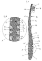
- Fig. 1 shows a schematic outline of a toothbrush according to the invention.
- Your toothbrush body is 1 with a head 10 intended to carry bristles 5, a neck 12 and a subsequent handle 14th fitted.
- the toothbrush body 1 consists of at least one Hard component 16, which serves as a basic structure 18 for Picking up and carrying at least one soft component 20 is trained.
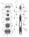
- Figs. 2 to 4 are different views of a Embodiment of the basic structure 18 according to the invention shown. Analogous to the toothbrush body 1 is divided also the skeletal basic structure 18 in a headboard 22, a neck portion 24 and a handle portion 26. Der Handle 26 has an elongated, spine-like, centrally in the handle 14 extending core 28th
- extensions 30, 32, 32 ', 32 in the form of in the longitudinal direction of the handle portion 26 against each other offset, open spaces forming ribs 30 and butt-like elevations 32.
- the ribs 30 are with respect to the longitudinal axis of the core 28 as well as the Raises 32 asymmetrically shaped and uneven in the Grip part 26 of the toothbrush body 1 distributed.
- a second group of extensions 32 '' is the height lower so that their radial outer surfaces 34 at the ready-to-use toothbrush from soft component 20 are covered.
- Fig. 2 is an approximately in the middle of the handle part arranged extension 321 with oval outer surface 34 and an extension 322 forming the end piece of the grip part 26 shown belonging to the group of extensions 32 '.
- Another four, near the neck portion 24 arranged ribs 323rd and nine, arranged at the free end of the handle portion 26 Ribs 324, 325 belong to the extensions 32 ''.
- the ribs 325 in the area of Wrist rest which has a circumferential angle of at least 180 ° to a maximum of 360 °, preferably of 270 ° to the Enclose the longitudinal axis of the toothbrush and one Have wavy circumferential line.
- the extensions 30, 32, 32 ', 32 "have radially outward preferably smooth outer surfaces 34 with round, oval, kidney-shaped or otherwise rounded shape.
- the core 28 of the handle portion 26 is placed in the neck portion 24 and the blade-like head portion 22 away.
- a Recess 36 in the head part 22 is for receiving bristles 5 or a bristle carrier 7 determined.
- the neck part 24 to reduce the bending stiffness sideways five staggered, semi-cylindrical indentations 38 on the ready toothbrush with the Soft component 20 are filled. Through the side Indentations 38 creates a flexible zone with a reduced flexural rigidity in the lateral direction. at same load will be the amount of deflection of the Head portion 22 against the handle portion 26 in a lateral Attack point to be greater than at a point of attack the top or bottom of the toothbrush.
- Fig. 4 is a channel-like recess 40, which is located on the bottom of the toothbrush body 1 from the handle side Beginning of the neck portion 24 to the free end of the Head portion 22 extends, shown.
- On the headboard 22 divides the recess 40 into two channel arms, which in Direction of the free head end merged again then into two circular Wells 41 to end.
- the depressions 40, 41 take the elastic soft component 20 on.
- the surface of the Soft component 20 of the head 10 is as a tongue scraper 42 formed for cleaning the tongue.
- hard component 16 for the basic structure 18 occur in particular the materials styrene and acrylonitrile (SAN), Polystyrene (PS), polyethylene terephthalate (PET), Acrylonitrile-butadiene-styrene copolymers (ABS), Polyethylene (PA) and preferably polypropylene (PP) for Commitment.
- SAN styrene and acrylonitrile
- PS Polystyrene
- PET polyethylene terephthalate
- ABS Acrylonitrile-butadiene-styrene copolymers
- PA Polyethylene
- PP polypropylene
- Fig. 5 to Fig. 7 are views of a according to the invention toothbrush shown.
- the toothbrush is composed of the toothbrush body 1 and the head 10th fasten bristles 5 together.
- the toothbrush body 1 consists of that shown in Fig. 2 to Fig. 4 Basic structure 18 and that of the basic structure 18 worn soft component 20.
- the neck 12 of the toothbrush body 1 is opposite the head 10 and the handle 14 tapers slightly. He starts in Direction of the head 10 after a broadening 44 of the Handle 14. The widening 44 serves as a thumb rest 58 and prevents when using the toothbrush Slipping of the thumb in the direction of the head 10. Referred on the total length of the toothbrush is the Length of the head 10 10% -25% of the neck 12 15% -30% and the handle 14 45% -75%.
- the soft component 20 fills those of the extensions 30, 32, 32 ', 32 "formed spaces of the basic structure 18 from. It covers the handle 14, with the exception of the outer surfaces 34 of the extensions 32 ', completely.
- the neck portion 24 and the Headboard 22 are partially, in particular to the Indentations 38 and the recesses 40, 41, covered.
- the overlap and thus the outer contour of the handle 14 is formed such that neither projections, paragraphs still other strong changes of direction, the Use the toothbrush to guide pressure points on the hand could occur.
- the soft component 20 preferably has almost its own entire outer surface of a surface structure 46 on.
- the soft component 20 has a maximum radial Thickness of 10 mm, giving the user a soft, flexible, dampening and non-slip grip surface ready.
- soft component 20 are preferred thermoplastic elastomers (TPE), which are compatible with the Hard component 16 enter into an affine connection to Commitment. To ensure a soft, pleasant feel becomes a TPE with a Shore A hardness of less than 70, particularly preferred having a Shore A hardness of less than 50 used.
- Fig. 5 to Fig. 7 indicates the surface of the soft component throughout Handle 14 and the neck of the neck 12 a honeycomb Surface structure 46 on.
- the Surface structure 46 from the top or bottom over the side surfaces continued continuously, but, preferably in the circumferential direction, enlarged or stretched executed.
- honeycomb Surface structure 46 are of course further Surface structures 46 possible. Particularly advantageous Embodiments are depicted in FIGS. 18 to 24 and will be described in detail later.
- the outer surfaces occur 34 of the extensions 32 'as islands 48.
- the islands 48 are surrounded by the soft component 20 and have a Expansion of at least 2mm x 2mm, preferably at least 4mm x 4mm.
- the islands 48 have a smooth surface in color the hard component 16 on.
- they can also by a similar or similar surface structure 46 as the surrounding soft component 20 and / or with Lettering, symbols, etc., such as a Company logo, covered or colored.
- the Structure, logos, symbols, etc. can be combined with a known technology, such as hot stamping or pad printing, be upset.
- the outer surfaces 34 of the islands 48th form a particular technical task in the Production process of the toothbrush. They serve at the preferably used technique of molding the Soft component 20 to the basic structure 18 within an injection mold in a defined position fix.
- FIG. 7 Schabernoppen 50 formed from the soft component 20. They form a tongue scraper 42, which is used for keeping clean and Massage of the tongue serves. His scraper nubs have 50 an elliptical or circular basic and Circular-shaped scraper surface 51 with a spoon-like An indentation for improved removal and absorption of scraped off material.
- the scraper nubs 50 are above the channel-like depressions 40 in the head part 22nd arranged offset from one another.
- the high of Scraper nubs 50 is a maximum of 3mm. Alternatively you can also differently shaped elevations partially or completely the Schabernoppen 50 shown in Fig. 7 replace.
- the toothbrush shown in FIGS. 5 to 7 is shown shown with a transparent soft component 20.
- the soft component 20 Through the soft component 20 are those of her covered extensions 32 '', the core 28 and the Indentations 38 visible on neck portion 24.
- the Outer surfaces 34 of the extensions 32 "can also despite the Cover by the soft component 20 by the user be felt. So is with a pleasant feel due to the continuous surface of the Soft component 20 a precise guidance of the toothbrush also ensured at different cleaning positions.
- the areas of the toothbrush that with a radially thicker Layer of the soft component 20 are covered appear due to shading by surrounding projections 30, 32, 32 ', 32 "darker than the only with a thin layer covered. This depth effect can be through use a lightly colored material for the soft component 20 be strengthened.
- the user recognizes by darker Appearing areas of the soft component 20 the Positions where the cross section of the core 28 a has particularly small diameter and the toothbrush thus having a flexible zone. With more frequent Use of the toothbrush will be darker by the user Areas intuitive with increased elasticity and Flexibility associated.
- FIG. 9 shows a section along the longitudinal axis of the toothbrush shown in FIGS. 5 to 8.
- the areas of the core 28 between the ribs 30 are particularly well visible.
- the core 28 is designed as a ball-shaped web 52 or as a cylinder-shaped web 52 '.
- the webs 52, 52 ' are shown in FIG. 9 and FIG. 10 as circular parts or trapezoids between the likewise trapezoidal cut surfaces of the ribs 30 protruding from the core 28.
- the webs 52, 52 ' may alternatively have other, compared to the maximum cross section of the core 28 weakened forms.
- the length of the webs 52, 52 ' is 3mm to 8mm.
- the volume of the spaces formed between the webs 52 by the ribs 30 is preferably completely filled with the soft component 20 and is between 500mm 3 and 2500mm 3 , preferably about 1500mm 3 .
- FIG. 11 the one already shown in FIGS. 5 to 10 is shown Toothbrush with markings E12 to E17 from Cross-sectional planes provided perpendicular to their longitudinal axis. These levels refer to the adjacent ones in FIG. 12 to 17 shown cross sections.
- Bristle bundles 54 are symmetrical with respect to a plane, which passes through the longitudinal axis of the toothbrush and parallel to the bristles 5 stands.
- the bristle bundles 54 have an organically shaped base with a Partial symmetry with respect to one of its major axes.
- the arrangement may also be partially symmetric or asymmetrical be executed. Both the shape of their preferred rounded bases as well as their specific Arrangement on the head 10 carries different Gebissformen Bill.
- the bristle bundles 54 point in their outer Edge region preferably a larger cross-section than in the center.
- the degree of hardness and Color distribution radially symmetric about the center of a Bristle bundle 54 executed.
- the Bristles 5 preferably in the edge region of a bristle bundle 54 a larger diameter than centrally in Bristle bundles 54 arranged bristles 5.
- the described Distributions of hardnesses and colors can also be over the entire, composed of bristle bundles 54 Borstenfeld continues to be.
- FIGS. 12 to 17 are cross sections perpendicular to Longitudinal axis of the toothbrush shown in Fig. 11 along the There marked cross-sectional planes E12 to E17 shown.
- the hard component 16 is shown in FIGS. 12 to 17 cross hatched shown.
- the soft component 20 is by a simple diagonal hatching characterized.
- Fig. 12 shows a cross section through the head 10 of Toothbrush according to FIG. 11.
- the hard component 16 has an M-shaped cross section, in the lower Recess 36 of the fixed by means of a known technique the bristle carrier 7 without bristles 5 connected to the head part 22 is shown.
- the two upper recesses 40 are filled with the soft component 20.
- the soft component 20 forms there on the surface already described Tongue Scraper 42. Above the right channel is a Scraper nubs 50 of the tongue scraper 42 cut.
- Fig. 13 shows a nearly circular rounded Cross section through the neck 12 of the toothbrush along the Section plane E13.
- the cross section is almost complete filled by the basic structure 18. Only the Channel-like recess 40 is connected to the soft component 20th refilled.
- the channel-like depression 40 extending from the Handle part 26 extends to the head part 22, provides the technical advantage that when using a Injection molding technology only a single injection point on the Toothbrush for applying the entire soft component 20 is needed.
- Fig. 14 shows in section a nearly complete of the Soft component 20 included part of the neck a circumferential line 56, the protuberances according to the cut surface structure 46 of the soft component 20 has.
- the basic structure 18 is in one piece formed asymmetrically in cross section and contributes to the already described, asymmetric bending stiffness with respect to the longitudinal axis of the toothbrush.
- Fig. 15 is a section through the handle 14 in the area the thumb rest 58, near the direction of the head 10 lying widening 44 shown.
- the concerning the Top and bottom of the toothbrush flattened, one rounded rectangle comparable cross-section allows An adequate use of the toothbrush even with a order for example, rotated 90 ° about the longitudinal axis Hold.
- the enclosed by the soft component 20 Basic structure 18 has the following truncated ones Elements on: in the left area a section through a Rib 323, in the upper part of the stump-like increase 32 "and left another truncated rib 323.
- the asymmetrically arranged extensions 323, 32 '' stand thereby transitionless from the core 28 off.
- Fig. 16 shows a cross section through the handle 14 at the Location of the appendage 321.
- the slightly flattened, but almost round basic shape of the cross-sectional area has a Circumferential line 56 with protuberances corresponding to Surface structure 46 on.
- On the top of the Toothbrush has the circumferential line 56 a smooth Segment derived from the island 48 of the extension 321.
- the extension 321 is seamless from the core 28 and has a radially outwardly decreasing width.
- FIG. 17 A cross section through the free end region of the handle 14, approximately at a support point of the handball, is shown in Fig. 17 shown.
- the cut runs directly through one ball-like web 52 and transitionless, right and left connected with him, asymmetrically in the longitudinal direction one after another staggered ribs 325th
- the section through the completely enclosing soft component 20 shows again a circumferential line 56 with protuberances corresponding to the truncated surface structure 46.
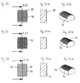
- Fig. 18 to Fig. 24b are further preferred Embodiments of the surface structure 46 indicated. They show in Fig. 18 to Fig. 24 plan views of Cutouts of the surface structure 46 of handles 14, in 18a to Fig. 24a cross sections of the cutouts along designated E18 to E24 in FIG. 18 to FIG. 24 Sectional planes and in Fig. 18b to Fig. 24b perspective Representations of those shown in Figures 18 to 24 Cutouts.
- Fig. 18 is a regular surface structure 46th of staggered, closely spaced ones Truncated pyramids 60 with rectangular bases shown.
- the arrangement forms a network of channels 62 with a wedge-shaped cross-section.
- These channels 62 cause fluids when using the toothbrush, For example, water continues from the handle 14 of the toothbrush.
- the in use coming in contact with the hand Roofs of the truncated pyramids 60 thus remain relative dry and increased stiction between the roofs and the hand surface prevents slipping of the hand from the grip 14.
- the structures of the skin form the sloping side surfaces and upper edges of the Pyramid stumps 60 additional positive locking Boundary connections, which also contribute to Prevent slipping.
- Fig. 19 shows irregularly running, almost of one common line pioneering beads 64 with semicircular cross sections.
- the beads 64 form along with the smooth surface channels 62 for removal of liquids. At the same time prevent the surveys 64 in positive interaction with the skin Slipping the hand off the handle 14.
- a surface structure 46 is shown regularly staggered, cylindrical Recesses 66 has. Form these blind holes 66 small cavities, which after slight pressure when grasping and masking by hand cause a suction effect. On this way will also slip your hand on the Grip surface diminished.
- Fig. 21 is a surface structure 46 with a large number of nubbly pronounced hemispheres 68 displayed. Through her regularly, against each other staggered arrangement they form drainage channels 62 for Liquids. In interaction with the skin surface is in turn positively locking the sliding of the hand on the Grip surface diminished.
- Fig. 22 shows an embodiment in which wavy, repetitive, segmented surveys 70 perpendicular to the longitudinal axis of the handle 14 in the same Distances are arranged parallel to each other. These Structure is also for the discharge of liquids suitable and also causes a mechanical Slip reduction.
- Embodiment form segment-like elevations on the Surface a honeycomb grid structure of cells 72nd with round or hexagonal recessed bases.
- Fig. 24 is a scale-like surface structure 46th shown. In a regular-staggered arrangement overlap at an angle of about 40 ° to the free end Part of the handle 14 out facing scales 74 partially their Predecessor shed. They form almost perpendicular to the Surface of the handle 14 from upright rear sides 76, the one hand slipping towards the head 10 prevent.
- This surface structure 46 is also in advantageously adapted to liquids over the Derive grip 14 away.
- All described surface structures 46 can be found in the Size, height and the distance or interval of their smallest, repetitive basic elements (Truncated pyramid 60, bead 64, cylindrical depression 66, hemisphere 68, wavy elevation 70, honeycomb cell 72, scale 74) on the surface of a handle 14, but Of course, between handles 14 different Toothbrushes vary.
- the distance and the height of the Basic elements 60, 64, 66, 68, 70, 72, 74 is smaller than 5mm and is preferably 0.5mm to 2mm.
- the Basic elements 60, 64, 66, 68, 70, 72, 74 of Surface structures 46 may be partial or complete through their negative form, that is a survey by their depression, etc., or other forms have been replaced.
- Their expansions are preferably on the side surfaces the toothbrush stretched and thus larger than at the Top and bottom of the toothbrush.
- On the side surfaces have the basic elements 60, 64, 66, 68, 70, 72, 74 preferably no elevations over the lateral, parallel to the longitudinal axis of the toothbrush and the bristles 5 extending tangential surfaces protrude.
- the production of the inventive toothbrush body 1 or the inventive toothbrush takes place preferably in a multi-step injection molding process.
- the basic structure 18 from the Hard component 16 preferably by means of a single Injection point, manufactured. This injection point is advantageously in the rear third of the handle portion 26th on an extension covered by the soft component 20 32 ".
- the basic structure 18 can also be used in one Multi-component method of two or more, For example, colored hard components 16 cast become. In this step, already written, Symbols, etc. on or through the hard component itself be formed.
- the base structure 18 one or several soft components 20 sprayed. At least one the soft component 20 is transparent or translucent.
- the soft components 20 can thereby be colored or colorless and also for the arrival or Applying lettering, symbols or other Embodiments are used.
- the bristles 5 on a bristle carrier 7 by means of the AFT (anchor free tufting) procedure, the IMT (inmold tufting) procedure or a conventional stuffing method attached. Subsequently, the stocked bristle carrier 7 in the Inserted on the head 10 and glued in there, cast or by another known technique attached.
- AFT anchor free tufting
- IMT inmold tufting
Landscapes
- Brushes (AREA)
Abstract
Description
- Fig. 1
- Schematischer Umriss einer erfindungsgemässen Zahnbürste;
- Fig. 2
- Draufsicht auf die Oberseite einer Grundstruktur eines erfindungsgemässen Zahnbürstenkörpers;
- Fig. 3
- Seitenansicht der Grundstruktur des Zahnbürstenkörpers aus Fig. 2;
- Fig. 4
- Draufsicht auf die Unterseite der Grundstruktur des Zahnbürstenkörpers aus Fig. 2;
- Fig. 5
- Draufsicht auf die Oberseite einer Zahnbürste mit einer Grundstruktur nach Fig. 2 bis Fig. 4 und wabenförmiger Oberflächenstruktur der Weichkomponente;
- Fig. 6
- Seitenansicht der Zahnbürste gemäss Fig. 5, die eine seitlich gedehnte Oberflächenstruktur aufweist;
- Fig. 7
- Draufsicht auf die Unterseite der Zahnbürste aus Fig. 5 mit einem Zungenschaber am Kopf;
- Fig. 8
- Perspektivische Ansicht der in Fig. 5 bis Fig. 7 gezeigten Zahnbürste mit einer durchsichtigen Weichkomponente und mit der Grundstruktur gemäss Fig. 2 bis Fig. 4;
- Fig. 9
- Längsschnitt durch die in Fig. 8 gezeigte Zahnbürste;
- Fig. 10
- Vergrösserte Schnittdarstellung des Ausschnitts A aus Fig. 9;
- Fig.
- 11 Draufsicht auf die Zahnbürste gemäss Fig. 5 bis Fig. 7 mit Markierungen von Querschnittsebenen E12 bis E17;
- Fig. 12 - 17
- Querschnitte durch die Zahnbürste aus Fig. 11 entlang den in Fig. 11 eingezeichneten Schnittebenen E12 bis E17;
- Fig. 18 - 24
- Ausschnitte von Draufsichten auf Griffoberflächen von Zahnbürsten mit verschieden Oberflächenstrukturen der Weichkomponente;
- Fig. 18a - 24a
- Schematische Längsschnitte entlang von in Fig. 18 bis Fig. 24 eingezeichneten Schnittebenen E18 - E23; und
- Fig. 18b - 24b
- Perspektivische Ansichten von in Fig. 18 bis Fig. 24 dargestellten Ausschnitten von Draufsichten auf Griffoberflächen.
Claims (16)
- Zahnbürstenkörper mit einem zum Tragen von Borsten (5) bestimmten Kopf (10), einem Hals (12) und einem daran anschliessenden Griff (14), wobei der Zahnbürstenkörper (1) aus mindestens einer Hartkomponente (16) besteht, die als eine Grundstruktur (18) zum Aufnehmen und Tragen mindestens einer Weichkomponente (20) ausgebildet ist, dadurch gekennzeichnet, dass die Grundstruktur (18) skelettartig ausgeformt ist und einen Griffteil (26) mit einem länglichen, rückgratartigen im Griff (14) angeordneten Kern (28) mit abstehenden Fortsätzen (30, 32, 32', 32") in Form von Rippen (30) und stumpfartigen Erhöhungen (32), die offene, mit der Weichkomponente (20) ausgefüllte Räume bilden, aufweist.
- Zahnbürstenkörper nach Anspruch 1, dadurch gekennzeichnet, dass der Kern (28) zentral im Griff (14) und nahezu parallel zu dessen Längsachse verläuft.
- Zahnbürstenkörper nach einem der Ansprüche 1 bis 2, dadurch gekennzeichnet, dass die Fortsätze (30, 32, 32', 32") in Längsrichtung des Griffs (14) gegeneinander versetzt angeordnet sind.
- Zahnbürstenkörper nach einem der Ansprüche 1 bis 3, dadurch gekennzeichnet, dass die Rippen (30) bezüglich der Längsachse des Kerns (28) und die Erhöhungen (32) asymmetrisch geformt sind.
- Zahnbürstenkörper nach einem der Ansprüche 1 bis 4, dadurch gekennzeichnet, dass der Kern (28) zwischen den Fortsätzen (30, 32, 32', 32'') als Steg (52, 52'), der im Vergleich zum maximalen Querschnitt des Kerns (28) geschwächt ist und dadurch eine flexible Zone bildet, ausgeformt ist, und dass der Steg (50, 52') vorzugsweise die Gestalt eines Zylinder- oder Kugelteils besitzt.
- Zahnbürstenkörper nach einem der Ansprüche 1 bis 5, dadurch gekennzeichnet, dass die Weichkomponente (20) die Räume der Grundstruktur (18) auffüllt und die Fortsätze (32'') mindestens teilweise überdeckt, wobei die maximale radiale Schichtdicke der Weichkomponente (20) vorzugsweise 10mm beträgt.
- Zahnbürstenkörper nach einem der Ansprüche 1 bis 6, dadurch gekennzeichnet, dass die Fortsätze (32'') radial aussen von einer filmartigen Schicht aus der Weichkomponente (20) mit einer im wesentlichen konstanten Dicke von weniger als 4mm, vorzugsweise von etwa 1mm, bedeckt sind.
- Zahnbürstenkörper nach einem der Ansprüche 1 bis 7, dadurch gekennzeichnet, dass die Fortsätze (32') mit ihren radialen Aussenflächen (34) an der Oberfläche der Zahnbürste Inseln (48) mit einer Fläche grösser als 2mm x 2mm, vorzugsweise von 4mm x 4mm bilden, die kontinuierliche, stufen- und absatzlose Übergange zur umgebenden Weichkomponente (20) aufweisen.
- Zahnbürstenkörper nach einem der Ansprüche 1 bis 8, dadurch gekennzeichnet, dass der überwiegende Teil der Oberfläche der Weichkomponente (20) im Bereich des Griffs (14) strukturiert, vorzugsweise netzartig, wabenartig, rillenartig, schuppen- oder noppenartig mit sich wiederholenden Grundelementen in Form von Pyramidenstümpfen (60), Wülsten (64), zylinderförmigen Vertiefungen (66), Halbkugeln (68), wellenförmigen Erhebungen (70), Wabenzellen (72) und Schuppen (74) strukturiert ist.
- Zahnbürstenkörper nach Anspruch 8, dadurch gekennzeichnet, dass die Oberfläche der Inseln (48) mindestens teilweise glatt oder strukturiert, vorzugsweise netzartig, wabenartig, rillenartig, schuppen- oder noppenartig mit sich wiederholenden Grundelementen in Form von Pyramidenstümpfen (60), Wülsten (64), zylinderförmigen Vertiefungen (66), Halbkugeln (68), wellenförmige Erhebungen (70), Wabenzellen (72) und Schuppen (74) strukturiert ist.
- Zahnbürstenkörper nach Anspruch 10, dadurch gekennzeichnet, dass die Struktur der Oberfläche der Inseln (48) und der Weichkomponente (20) in ihrer Grösse und Höhe variiert und an den nahezu parallel zur Längsachse der Borsten (5) verlaufenden Seitenflächen der Zahnbürste in Umfangsrichtung gedehnt ist.
- Zahnbürstenkörper nach einem der Ansprüche 1 bis 11, dadurch gekennzeichnet, dass die Weichkomponente (20) durchsichtig oder durchscheinend und/oder leicht gefärbt ist und somit die von der Weichkomponente (20) überdeckten Fortsätze (32") und die Tiefe der von der Grundstruktur (18) gebildeten offenen Räume sichtbar bzw. wahrnehmbar sind.
- Zahnbürstenkörper nach einem der Ansprüche 1 bis 12, dadurch gekennzeichnet, dass sich der Kern (28) der Grundstruktur (18) vom Griffteil (26) in einen Halsteil (24) und einen Kopfteil (22) fortsetzt und der Halsteil (24) mit gegeneinander versetzten, asymmetrisch angeordneten Einbuchtungen (38) ausgestattet ist.
- Zahnbürstenkörper nach einem der Ansprüche 1 bis 13, dadurch gekennzeichnet, dass die Stärke und Richtung der Biegesteifigkeit des Zahnbürstenkörpers (1) entlang seiner Längsachse auch an Orten mit näherungsweise gleichem Durchmesser des Querschnitts des Zahnbürstenkörpers (1) aufgrund von unterschiedlichen Volumina der von den Fortsätzen (30, 32, 32', 32") gebildeten Räume und von verschiedenen Abständen zwischen den Fortsätzen (30, 32, 32', 32 ") variiert.
- Zahnbürstenkörper nach einem der Ansprüche 1 bis 14, dadurch gekennzeichnet, dass der Kopf (10) auf der einer Ausnehmung (36) gegenüberliegenden Unterseite des Zahnbürstenkörpers (1) einen aus der Weichkomponente (20) geformten Zungenschaber (42) mit Schabernoppen (50), die eine elliptische oder kreisförmige Grund- und kreisteilförmige Schaberfläche (51) mit einer löffelartigen Einwölbung besitzen, aufweist.
- Zahnbürste mit einem Zahnbürstenkörper (1) nach einem der Ansprüche 1 bis 15, dadurch gekennzeichnet, dass der Zahnbürstenkörper (1) am Kopf (10) mit in Borstenbündeln (54) zusammenstehenden Borsten (5), die unterschiedliche Härtegrade und Farben aufweisen können, besetzt ist.
Priority Applications (5)
| Application Number | Priority Date | Filing Date | Title |
|---|---|---|---|
| DE50313511T DE50313511D1 (de) | 2003-11-18 | 2003-11-18 | Zahnbürstenkörper |
| AT03026376T ATE499860T1 (de) | 2003-11-18 | 2003-11-18 | Zahnbürstenkörper |
| EP03026376A EP1532891B1 (de) | 2003-11-18 | 2003-11-18 | Zahnbürstenkörper |
| PCT/EP2004/012521 WO2005048772A1 (de) | 2003-11-18 | 2004-11-05 | Handgriffkörper für körperpflegeinstrumente |
| US11/386,889 US7383619B2 (en) | 2003-11-18 | 2006-03-23 | Handle body for body care implements |
Applications Claiming Priority (1)
| Application Number | Priority Date | Filing Date | Title |
|---|---|---|---|
| EP03026376A EP1532891B1 (de) | 2003-11-18 | 2003-11-18 | Zahnbürstenkörper |
Publications (2)
| Publication Number | Publication Date |
|---|---|
| EP1532891A1 true EP1532891A1 (de) | 2005-05-25 |
| EP1532891B1 EP1532891B1 (de) | 2011-03-02 |
Family
ID=34429381
Family Applications (1)
| Application Number | Title | Priority Date | Filing Date |
|---|---|---|---|
| EP03026376A Expired - Lifetime EP1532891B1 (de) | 2003-11-18 | 2003-11-18 | Zahnbürstenkörper |
Country Status (5)
| Country | Link |
|---|---|
| US (1) | US7383619B2 (de) |
| EP (1) | EP1532891B1 (de) |
| AT (1) | ATE499860T1 (de) |
| DE (1) | DE50313511D1 (de) |
| WO (1) | WO2005048772A1 (de) |
Cited By (7)
| Publication number | Priority date | Publication date | Assignee | Title |
|---|---|---|---|---|
| EP1836923A1 (de) * | 2006-03-24 | 2007-09-26 | Trisa Holding AG | Zahnbürste mit Facettengriff |
| EP1905382A1 (de) | 2006-09-29 | 2008-04-02 | Trisa Holding AG | Elektrozahnbürste und Getriebe für eine Elektrozahnbürste |
| DE102007017869A1 (de) | 2007-04-13 | 2008-10-16 | Braun Gmbh | Zahnbürste |
| US9398802B2 (en) | 2012-03-09 | 2016-07-26 | Colgate-Palmolive Company | Method of forming a head plate and formation of oral care implement using the same |
| US9737134B2 (en) | 2012-03-22 | 2017-08-22 | Colgate-Palmolive Company | Oral care implement having flexible handle |
| EP3607854A1 (de) * | 2018-08-06 | 2020-02-12 | Trisa Holding AG | Mundhygienemittel, inbesondere eine zahnbürste |
| EP1745217B2 (de) † | 2004-05-03 | 2020-04-15 | Schmidt, Patrick | Unterdruck-haltevorrichtung |
Families Citing this family (104)
| Publication number | Priority date | Publication date | Assignee | Title |
|---|---|---|---|---|
| CA2596795A1 (en) * | 2005-02-03 | 2006-08-10 | Bic-Violex Sa | Razor handle having ergonomic gripping areas |
| WO2007000184A1 (en) * | 2005-06-28 | 2007-01-04 | Bic-Violex Sa | Improvements to razor handle grips |
| CN101341007A (zh) * | 2005-12-22 | 2009-01-07 | 皇家飞利浦电子股份有限公司 | 一种手柄 |
| US20070238544A1 (en) * | 2006-04-05 | 2007-10-11 | Joseph Jazwiec | Golf Putter with Alignment Head |
| AU313327S (en) * | 2006-06-02 | 2007-03-13 | Braun Gmbh | Toothbrush |
| USD571955S1 (en) | 2007-03-07 | 2008-06-24 | American Safety Razor | Shaving razor |
| USD621621S1 (en) * | 2007-04-23 | 2010-08-17 | The Procter & Gamble Company | Toothbrush |
| DE102007019908A1 (de) * | 2007-04-27 | 2008-10-30 | Braun Gmbh | Vorrichtung zur Zahn- und/oder Mundreinigung |
| US20090072610A1 (en) * | 2007-09-14 | 2009-03-19 | Alan Vincent Sorrentino | Method of providing a decorative member on a toothbrush |
| US8435433B2 (en) * | 2008-02-04 | 2013-05-07 | The Gillette Company | Method for making a handle for a personal grooming device |
| USD666005S1 (en) * | 2008-04-21 | 2012-08-28 | Braun Gmbh | Portion of a toothbrush handle |
| US8510893B2 (en) | 2008-06-20 | 2013-08-20 | Colgate-Palmolive Company | Toothbrush with visual and/or other sensory effects |
| AU2012200354B2 (en) * | 2008-06-20 | 2012-08-02 | Colgate-Palmolive Company | Toothbrush with visual and/or other sensory effects |
| AU2015203770B2 (en) * | 2008-06-20 | 2015-10-08 | Colgate-Palmolive Company | Toothbrush with visual and/or other sensory effects |
| USD651406S1 (en) | 2008-06-20 | 2012-01-03 | Colgate-Palmolive Company | Toothbrush handle |
| USD645252S1 (en) * | 2008-08-15 | 2011-09-20 | Mcneil-Ppc, Inc. | Toothbrush |
| US8151468B2 (en) * | 2008-09-26 | 2012-04-10 | The Gillette Company | Handle for shaving razors having improved grip |
| USD658885S1 (en) | 2008-09-30 | 2012-05-08 | Mcneil-Ppc, Inc. | Toothbrush handle |
| US20100101034A1 (en) * | 2008-10-27 | 2010-04-29 | Acumen Co., Ltd. | Handle for a brush |
| USD604906S1 (en) | 2008-11-07 | 2009-11-24 | American Safety Razor | Shaving razor handle |
| USD651407S1 (en) | 2009-01-23 | 2012-01-03 | Colgate-Palmolive Company | Toothbrush |
| USD625882S1 (en) | 2009-05-21 | 2010-10-19 | American Safety Razor | Shaving razor |
| USD615704S1 (en) | 2009-05-21 | 2010-05-11 | American Safety Razor | Shaving razor |
| USD658884S1 (en) | 2009-05-27 | 2012-05-08 | Mcneil-Ppc, Inc. | Toothbrush |
| US20110041271A1 (en) * | 2009-08-19 | 2011-02-24 | Acumen Co., Ltd. | Interdental brush |
| USD640004S1 (en) | 2009-11-30 | 2011-06-14 | American Safety Razor | Shaving razor |
| USD633252S1 (en) | 2009-11-30 | 2011-02-22 | American Safety Razor | Shaving razor |
| USD640414S1 (en) | 2009-11-30 | 2011-06-21 | American Safety Razor | Shaving razor |
| USD654270S1 (en) | 2009-12-18 | 2012-02-21 | Colgate-Palmolive Company | Toothbrush handle |
| USD632484S1 (en) | 2009-12-18 | 2011-02-15 | Eduardo Jimenez | Toothbrush handle with tissue cleaner |
| USD654695S1 (en) | 2009-12-18 | 2012-02-28 | Colgate-Palmolive Company | Toothbrush |
| USD675830S1 (en) | 2009-12-18 | 2013-02-12 | Colgate-Palmolive Company | Toothbrush |
| RU2514697C2 (ru) * | 2009-12-18 | 2014-05-10 | Колгейт-Палмолив Компани | Приспособление для ухода за ротовой полостью, имеющее корпус, расположенный внутри ручки |
| USD654696S1 (en) | 2009-12-18 | 2012-02-28 | Colgate-Palmolive Company | Toothbrush handle with tissue cleaner |
| USD657569S1 (en) | 2010-02-26 | 2012-04-17 | Colgate-Palmolive Company | Head portion of an oral care implement |
| USD657568S1 (en) | 2010-02-26 | 2012-04-17 | Colgate-Palmolive Company | Oral care implement |
| USD676245S1 (en) * | 2010-03-30 | 2013-02-19 | Colgate-Palmolive Company | Oral care implement |
| USD636533S1 (en) | 2010-05-11 | 2011-04-19 | American Safety Razor | Razor handle |
| USD635718S1 (en) | 2010-05-12 | 2011-04-05 | American Safety Razor | Razor handle |
| USD636938S1 (en) | 2010-05-12 | 2011-04-26 | American Safety Razor | Razor handle |
| JP5669473B2 (ja) * | 2010-07-27 | 2015-02-12 | 株式会社貝印刃物開発センター | 剃刀のハンドル |
| US8720072B2 (en) * | 2010-08-11 | 2014-05-13 | Thomas J. Bucco | Razor with three-axis multi-position capability |
| PL2642886T3 (pl) | 2010-11-22 | 2017-12-29 | Braun Gmbh | Szczoteczka do zębów |
| US8732890B2 (en) * | 2010-11-22 | 2014-05-27 | Braun Gmbh | Toothbrush |
| MX338596B (es) * | 2011-02-01 | 2016-04-22 | Colgate Palmolive Co | Implemento del cuidado bucal que tiene un elemento decorativo y un metodo para formar el mismo. |
| WO2012121806A2 (en) * | 2011-03-10 | 2012-09-13 | Lavery Terrence J | Razor blade cleaning brush |
| USD678679S1 (en) * | 2011-06-15 | 2013-03-26 | Colgate-Palmolive Company | Toothbrush |
| USD678680S1 (en) * | 2011-06-15 | 2013-03-26 | Colgate-Palmolive Company | Toothbrush |
| JP5830277B2 (ja) * | 2011-06-20 | 2015-12-09 | ライオン株式会社 | 歯ブラシ |
| EP2554353B1 (de) * | 2011-08-05 | 2017-06-07 | Trisa Holding AG | Verfahren zur Herstellung einer Zahnbürste und Zahnbürste |
| USD677061S1 (en) | 2012-08-30 | 2013-03-05 | Jean M. Barry | Ergonomic brush handle |
| US9427074B2 (en) * | 2012-12-10 | 2016-08-30 | Colgate-Palmolive Company | Oral care implement |
| US20140230256A1 (en) * | 2013-02-20 | 2014-08-21 | The Gillette Company | Hand held device |
| US9101204B2 (en) * | 2013-09-26 | 2015-08-11 | M+C Schiffer Gmbh | Oral care implement |
| JP1517366S (de) * | 2014-07-31 | 2015-02-16 | ||
| CN107072387B (zh) | 2014-11-10 | 2019-09-17 | 高露洁-棕榄公司 | 具有光透射手柄的牙刷 |
| RU2664278C1 (ru) | 2014-12-23 | 2018-08-15 | Колгейт-Палмолив Компани | Устройство для ухода за полостью рта, содержащее многокомпонентную ручку |
| MX393731B (es) | 2014-12-23 | 2025-03-24 | Colgate Palmolive Co | Implemento para el cuidado bucal. |
| US11291293B2 (en) | 2014-12-23 | 2022-04-05 | Colgate-Palmolive Company | Oral care implement |
| USD780457S1 (en) | 2014-12-23 | 2017-03-07 | Colgate-Palmolive Company | Oral care implement |
| US10455931B2 (en) | 2014-12-23 | 2019-10-29 | Colgate-Palmolive Company | Oral care implement |
| WO2016105374A1 (en) | 2014-12-23 | 2016-06-30 | Colgate-Palmolive Company | Oral care implement |
| EP3995036B1 (de) | 2014-12-23 | 2025-06-04 | Colgate-Palmolive Company | Mundpflegevorrichtung |
| BR112017010792B1 (pt) | 2014-12-23 | 2021-10-05 | Colgate-Palmolive Company | Instrumento de higiene bucal |
| US10660430B2 (en) | 2014-12-23 | 2020-05-26 | Colgate-Palmolive Company | Oral care implement having multi-component handle |
| EP3223657B1 (de) | 2014-12-23 | 2022-12-07 | Colgate-Palmolive Company | Mundpflegevorrichtung |
| CA2970634C (en) | 2014-12-23 | 2022-04-12 | Colgate-Palmolive Company | Oral care implement having multi-component handle |
| EP3223655B1 (de) | 2014-12-23 | 2024-10-09 | Colgate-Palmolive Company | Mundpflegevorrichtung |
| USD780458S1 (en) * | 2015-01-16 | 2017-03-07 | Radius Corporation | Toothbrush |
| US9802347B2 (en) | 2015-02-02 | 2017-10-31 | Colgate-Palmolive Company | Method of forming an oral care implement |
| US9402462B1 (en) * | 2015-05-05 | 2016-08-02 | Braun Gmbh | Oral-care implement having spring-loaded cleaning elements |
| USD777446S1 (en) | 2015-07-23 | 2017-01-31 | Colgate-Palmolive Company | Oral care implement handle |
| WO2017012109A1 (en) | 2015-07-23 | 2017-01-26 | Colgate-Palmolive Company | Oral care implement |
| JP2017121267A (ja) * | 2016-01-04 | 2017-07-13 | ライオン株式会社 | 歯ブラシ |
| DE102016005012A1 (de) * | 2016-04-26 | 2017-10-26 | Interbros Gmbh | Interdentalreiniger |
| US20170318946A1 (en) * | 2016-04-29 | 2017-11-09 | Michael Davidson | Toothbrush and method of manufacturing and using the same |
| US11285630B2 (en) | 2016-08-11 | 2022-03-29 | The Gillette Company Llc | Handle for a razor |
| US10414058B2 (en) | 2016-08-11 | 2019-09-17 | The Gillette Company Llc | Handle for a razor |
| US10226874B2 (en) | 2016-08-11 | 2019-03-12 | The Gillette Company Llc | Handle for a razor |
| US10940598B2 (en) | 2016-08-11 | 2021-03-09 | The Gillette Company Llc | Handle for a razor |
| US11130247B2 (en) * | 2016-08-11 | 2021-09-28 | The Gillette Company Llc | Handle for a razor |
| USD806959S1 (en) * | 2017-02-22 | 2018-01-02 | Avian Cafe Corporation | Oriole feeder |
| CA182566S (en) * | 2017-03-22 | 2018-08-23 | Gillette Co Llc | Toothbrush |
| US20190084169A1 (en) * | 2017-09-15 | 2019-03-21 | Little Acorn Shave Company Inc. | Razor handle |
| USD834325S1 (en) * | 2017-09-21 | 2018-11-27 | The Gillette Company Llc | Toothbrush handle |
| USD833756S1 (en) * | 2017-09-21 | 2018-11-20 | The Gillette Company Llc | Toothbrush handle |
| USD834324S1 (en) * | 2017-09-21 | 2018-11-27 | The Gillette Company Llc | Toothbrush |
| USD833757S1 (en) * | 2017-09-21 | 2018-11-20 | The Gillette Company Llc | Toothbrush handle |
| US10709533B2 (en) | 2017-12-12 | 2020-07-14 | Colgate-Palmolive Company | Oral care implement and handle and refill head thereof |
| US10631964B2 (en) | 2017-12-12 | 2020-04-28 | Colgate-Palmolive Company | Oral care implement |
| USD846883S1 (en) | 2017-12-12 | 2019-04-30 | Colgate-Palmolive Company | Handle of an oral care implement |
| US10925384B2 (en) | 2018-04-16 | 2021-02-23 | Colgate-Palmolive Company | Oral care implement |
| USD891784S1 (en) | 2018-12-18 | 2020-08-04 | Colgate-Palmolive Company | Electric toothbrush handle |
| US11800924B2 (en) | 2019-12-03 | 2023-10-31 | Colgate-Palmolive Company | Oral care implement |
| USD971608S1 (en) | 2019-12-03 | 2022-12-06 | Colgate-Palmolive Company | Toothbrush |
| US11350729B2 (en) | 2019-12-03 | 2022-06-07 | Colgate-Palmolive Company | Oral care implement |
| US12290211B2 (en) * | 2020-06-15 | 2025-05-06 | Chase Johns | Eggshell extraction implement |
| PL3995040T3 (pl) * | 2020-11-06 | 2025-06-16 | The Gillette Company Llc | Rękojeść urządzenia do higieny osobistej i urządzenie do higieny osobistej |
| USD960582S1 (en) | 2020-12-10 | 2022-08-16 | Colgate-Palmolive Company | Oral care refill head |
| JP7619804B2 (ja) | 2020-12-28 | 2025-01-22 | アース製薬株式会社 | 塗布用ブラシ |
| CN220554522U (zh) * | 2023-08-29 | 2024-03-05 | 广州星际悦动股份有限公司 | 电动牙刷头及电动牙刷 |
| USD1108813S1 (en) * | 2024-04-04 | 2026-01-13 | Trisa Holding Ag | Toothbrush handle |
| DE102025000349B4 (de) | 2025-01-29 | 2025-12-18 | Jovica Vukosavljevic | Zahnbürste |
| DE102026001036A1 (de) | 2026-02-24 | 2026-04-30 | Jovica Vukosavljevic | Zahnbürste mit haptischer Wahrnehmung einer zu hohen Putzkraft |
Citations (10)
| Publication number | Priority date | Publication date | Assignee | Title |
|---|---|---|---|---|
| US1899242A (en) * | 1932-03-02 | 1933-02-28 | Mcnab Alexander | Toothbrush holder |
| US2360745A (en) * | 1942-04-10 | 1944-10-17 | Sidney A Vogel | Toothbrush |
| FR1005685A (fr) * | 1947-09-06 | 1952-04-15 | Perfectionnement aux manches de brosses | |
| DE4222931C1 (de) | 1992-07-11 | 1993-12-09 | Henkel Kgaa | Zahnbürste |
| WO1997025899A1 (en) * | 1996-01-18 | 1997-07-24 | The Procter & Gamble Company | A toothbrush with elastomer filled flexible head |
| US5781958A (en) * | 1996-02-14 | 1998-07-21 | Gillette Canada Inc. | Brush handle |
| WO2001017391A1 (en) * | 1999-09-08 | 2001-03-15 | The Procter & Gamble Company | A handle for a toothbrush |
| US6298516B1 (en) | 1998-03-06 | 2001-10-09 | Gillette Canada Company | Toothbrushes |
| WO2002078489A1 (en) | 2001-03-30 | 2002-10-10 | Unilever N.V. | Toothbrush |
| US20020170145A1 (en) * | 1998-05-08 | 2002-11-21 | John O. Butler Company | Dental hygiene system handle |
Family Cites Families (11)
| Publication number | Priority date | Publication date | Assignee | Title |
|---|---|---|---|---|
| DE608820C (de) * | 1933-11-07 | 1935-02-01 | Leo Axien | Rasierapparat mit biegsamem Handgriff |
| DE3622596A1 (de) * | 1985-07-08 | 1987-01-15 | Heinz Rauh | Aus thermoplastischem kunststoff bestehender griff |
| GB8807673D0 (en) * | 1988-03-31 | 1988-05-05 | Lingner & Fischer Gmbh | Novel article |
| US5398369A (en) * | 1994-07-07 | 1995-03-21 | Chesebrough-Pond's Usa Co., Division Of Conopco, Inc. | Toothbrush with pliable pressure pad |
| US6408476B1 (en) | 1996-01-18 | 2002-06-25 | The Procter & Gamble Company | Toothbrush with elastomer filled flexible head |
| US5784790A (en) * | 1996-04-10 | 1998-07-28 | The Gillette Company | Shaving razor and method |
| US5687485A (en) * | 1996-05-15 | 1997-11-18 | The Gillette Company | Razor handle |
| US5862571A (en) | 1997-01-10 | 1999-01-26 | Hp Intellectual Corp. | Comfort grip handle and process |
| JPH1194239A (ja) | 1997-09-26 | 1999-04-09 | Nippon Furnace Kogyo Kaisha Ltd | 交互切換蓄熱再生バーナシステム及びその燃焼制御方法 |
| CA2263771A1 (en) * | 1999-03-01 | 2000-09-01 | Genevieve Christianne Proulx | Improved toothbrush handle |
| US7047591B2 (en) * | 2002-09-20 | 2006-05-23 | Colgate-Palmolive Company | Oral care implement |
-
2003
- 2003-11-18 DE DE50313511T patent/DE50313511D1/de not_active Expired - Lifetime
- 2003-11-18 AT AT03026376T patent/ATE499860T1/de active
- 2003-11-18 EP EP03026376A patent/EP1532891B1/de not_active Expired - Lifetime
-
2004
- 2004-11-05 WO PCT/EP2004/012521 patent/WO2005048772A1/de not_active Ceased
-
2006
- 2006-03-23 US US11/386,889 patent/US7383619B2/en not_active Expired - Lifetime
Patent Citations (10)
| Publication number | Priority date | Publication date | Assignee | Title |
|---|---|---|---|---|
| US1899242A (en) * | 1932-03-02 | 1933-02-28 | Mcnab Alexander | Toothbrush holder |
| US2360745A (en) * | 1942-04-10 | 1944-10-17 | Sidney A Vogel | Toothbrush |
| FR1005685A (fr) * | 1947-09-06 | 1952-04-15 | Perfectionnement aux manches de brosses | |
| DE4222931C1 (de) | 1992-07-11 | 1993-12-09 | Henkel Kgaa | Zahnbürste |
| WO1997025899A1 (en) * | 1996-01-18 | 1997-07-24 | The Procter & Gamble Company | A toothbrush with elastomer filled flexible head |
| US5781958A (en) * | 1996-02-14 | 1998-07-21 | Gillette Canada Inc. | Brush handle |
| US6298516B1 (en) | 1998-03-06 | 2001-10-09 | Gillette Canada Company | Toothbrushes |
| US20020170145A1 (en) * | 1998-05-08 | 2002-11-21 | John O. Butler Company | Dental hygiene system handle |
| WO2001017391A1 (en) * | 1999-09-08 | 2001-03-15 | The Procter & Gamble Company | A handle for a toothbrush |
| WO2002078489A1 (en) | 2001-03-30 | 2002-10-10 | Unilever N.V. | Toothbrush |
Cited By (20)
| Publication number | Priority date | Publication date | Assignee | Title |
|---|---|---|---|---|
| EP1745217B2 (de) † | 2004-05-03 | 2020-04-15 | Schmidt, Patrick | Unterdruck-haltevorrichtung |
| US8448284B2 (en) | 2006-03-24 | 2013-05-28 | Trisa Holding Ag | Toothbrush with faceted handle |
| WO2007110208A1 (de) * | 2006-03-24 | 2007-10-04 | Trisa Holding Ag | Zahnbürste mit facettengriff |
| EP1836923A1 (de) * | 2006-03-24 | 2007-09-26 | Trisa Holding AG | Zahnbürste mit Facettengriff |
| US9125714B2 (en) | 2006-09-29 | 2015-09-08 | Trisa Holding Ag | Electric toothbrush, and transmission for an electric toothbrush |
| US9968427B2 (en) | 2006-09-29 | 2018-05-15 | Trisa Holding Ag | Electric toothbrush, and transmission for an electric toothbrush |
| DE202007019478U1 (de) | 2006-09-29 | 2012-11-09 | Trisa Holding Ag | Elektrozahnbürste und Getriebe für eine Elektrozahnbürste |
| EP2548531A2 (de) | 2006-09-29 | 2013-01-23 | Trisa Holding AG | Elektrozahnbürste und Getriebe für eine Elektrozahnbürste |
| US8365335B2 (en) | 2006-09-29 | 2013-02-05 | Trisa Holding Ag | Electric toothbrush, and transmission for an electric toothbrush |
| EP1905382A1 (de) | 2006-09-29 | 2008-04-02 | Trisa Holding AG | Elektrozahnbürste und Getriebe für eine Elektrozahnbürste |
| WO2008040401A1 (de) | 2006-09-29 | 2008-04-10 | Trisa Holding Ag | Elektrozahnbürste und getriebe für eine elektrozahnbürste |
| EP3610830A1 (de) | 2006-09-29 | 2020-02-19 | Trisa Holding AG | Aufsteckbürste für eine elektrozahnbürste |
| US9572642B2 (en) | 2006-09-29 | 2017-02-21 | Trisa Holding Ag | Electric toothbrush, and transmission for an electric toothbrush |
| EP2272463A2 (de) | 2006-09-29 | 2011-01-12 | Trisa Holding AG | Elektrozahnbürste und Getriebe für eine Elektrozahnbürste |
| DE102007017869A1 (de) | 2007-04-13 | 2008-10-16 | Braun Gmbh | Zahnbürste |
| US9398802B2 (en) | 2012-03-09 | 2016-07-26 | Colgate-Palmolive Company | Method of forming a head plate and formation of oral care implement using the same |
| US9737134B2 (en) | 2012-03-22 | 2017-08-22 | Colgate-Palmolive Company | Oral care implement having flexible handle |
| EP3607854A1 (de) * | 2018-08-06 | 2020-02-12 | Trisa Holding AG | Mundhygienemittel, inbesondere eine zahnbürste |
| WO2020030511A1 (de) * | 2018-08-06 | 2020-02-13 | Trisa Holding Ag | Mundhygienemittel, insbesondere eine zahnbürste |
| US11944188B2 (en) | 2018-08-06 | 2024-04-02 | Trisa Holding Ag | Oral hygiene product, in particular toothbrush |
Also Published As
| Publication number | Publication date |
|---|---|
| WO2005048772A1 (de) | 2005-06-02 |
| ATE499860T1 (de) | 2011-03-15 |
| US7383619B2 (en) | 2008-06-10 |
| DE50313511D1 (de) | 2011-04-14 |
| EP1532891B1 (de) | 2011-03-02 |
| US20060213018A1 (en) | 2006-09-28 |
Similar Documents
| Publication | Publication Date | Title |
|---|---|---|
| EP1532891B1 (de) | Zahnbürstenkörper | |
| EP2023771B1 (de) | Mundhygienegerät | |
| DE69513286T2 (de) | Zahnbürste mit elastischer fingerauflage | |
| DE3148797C2 (de) | ||
| DE60120833T2 (de) | Vorrichtung zum Auftragen eines kosmetischen oder pflegenden Produktes auf keratinische Faser, insbesondere auf Wimpern oder Augenbrauen | |
| DE69621025T2 (de) | Zahnbürste | |
| DE60311524T2 (de) | Zahnbürste | |
| DE69533930T2 (de) | Zahnbürste | |
| DE7911966U1 (de) | Applikator, brauchbar zur hautmassage | |
| DE60109357T2 (de) | Vorrichtung zum Auftragen eines kosmetischen oder pflegenden Produktes auf keratinische Fasern, insbesondere auf Wimpern oder Augenbrauen | |
| DE602004001667T2 (de) | Zahnbürste | |
| WO2006012938A2 (de) | Zahnbürste mit ausnehmungen | |
| WO2009149569A1 (de) | Bürste | |
| DE202015009704U1 (de) | Haarbürste | |
| DE10259723A1 (de) | Zahnbürste und Verfahren zu deren Herstellung | |
| EP1924167A1 (de) | Handgriff für eine bürste, insbesondere zahnbürste | |
| DE202016103629U1 (de) | Kosmetikapplikator mit Beflockung und Borsten | |
| DE2550256C3 (de) | Abstreifer für einen kosmetischen Stift mit einem Applikator | |
| EP0910275B1 (de) | Offenporiger, flexibler reinigungskörper | |
| DE60107276T2 (de) | Zahnbürste | |
| DE8028200U1 (de) | Manuelles massagegeraet | |
| DE102007015069A1 (de) | Handgriff für ein Werkzeug, insbesondere einen Schraubendreher | |
| DE2240460B2 (de) | Seifenstück insbesondere für die Handreinigung | |
| AT512894B1 (de) | Einsatz für Protektoren und Rohling für einen solchen Einsatz | |
| DE2312318A1 (de) | Buerste zur sach- und koerperpflege bzw. reinigung |
Legal Events
| Date | Code | Title | Description |
|---|---|---|---|
| PUAI | Public reference made under article 153(3) epc to a published international application that has entered the european phase |
Free format text: ORIGINAL CODE: 0009012 |
|
| AK | Designated contracting states |
Kind code of ref document: A1 Designated state(s): AT BE BG CH CY CZ DE DK EE ES FI FR GB GR HU IE IT LI LU MC NL PT RO SE SI SK TR |
|
| AX | Request for extension of the european patent |
Extension state: AL LT LV MK |
|
| 17P | Request for examination filed |
Effective date: 20051117 |
|
| AKX | Designation fees paid |
Designated state(s): AT BE BG CH CY CZ DE DK EE ES FI FR GB GR HU IE IT LI LU MC NL PT RO SE SI SK TR |
|
| 17Q | First examination report despatched |
Effective date: 20090908 |
|
| GRAP | Despatch of communication of intention to grant a patent |
Free format text: ORIGINAL CODE: EPIDOSNIGR1 |
|
| GRAS | Grant fee paid |
Free format text: ORIGINAL CODE: EPIDOSNIGR3 |
|
| GRAA | (expected) grant |
Free format text: ORIGINAL CODE: 0009210 |
|
| AK | Designated contracting states |
Kind code of ref document: B1 Designated state(s): AT BE BG CH CY CZ DE DK EE ES FI FR GB GR HU IE IT LI LU MC NL PT RO SE SI SK TR |
|
| REG | Reference to a national code |
Ref country code: GB Ref legal event code: FG4D Free format text: NOT ENGLISH |
|
| REG | Reference to a national code |
Ref country code: CH Ref legal event code: EP Ref country code: CH Ref legal event code: NV Representative=s name: PATENTANWAELTE SCHAAD, BALASS, MENZL & PARTNER AG |
|
| REG | Reference to a national code |
Ref country code: IE Ref legal event code: FG4D Free format text: LANGUAGE OF EP DOCUMENT: GERMAN |
|
| REF | Corresponds to: |
Ref document number: 50313511 Country of ref document: DE Date of ref document: 20110414 Kind code of ref document: P |
|
| REG | Reference to a national code |
Ref country code: DE Ref legal event code: R096 Ref document number: 50313511 Country of ref document: DE Effective date: 20110414 |
|
| REG | Reference to a national code |
Ref country code: NL Ref legal event code: T3 |
|
| PG25 | Lapsed in a contracting state [announced via postgrant information from national office to epo] |
Ref country code: GR Free format text: LAPSE BECAUSE OF FAILURE TO SUBMIT A TRANSLATION OF THE DESCRIPTION OR TO PAY THE FEE WITHIN THE PRESCRIBED TIME-LIMIT Effective date: 20110603 Ref country code: ES Free format text: LAPSE BECAUSE OF FAILURE TO SUBMIT A TRANSLATION OF THE DESCRIPTION OR TO PAY THE FEE WITHIN THE PRESCRIBED TIME-LIMIT Effective date: 20110613 Ref country code: SE Free format text: LAPSE BECAUSE OF FAILURE TO SUBMIT A TRANSLATION OF THE DESCRIPTION OR TO PAY THE FEE WITHIN THE PRESCRIBED TIME-LIMIT Effective date: 20110302 |
|
| PG25 | Lapsed in a contracting state [announced via postgrant information from national office to epo] |
Ref country code: CY Free format text: LAPSE BECAUSE OF FAILURE TO SUBMIT A TRANSLATION OF THE DESCRIPTION OR TO PAY THE FEE WITHIN THE PRESCRIBED TIME-LIMIT Effective date: 20110302 Ref country code: SI Free format text: LAPSE BECAUSE OF FAILURE TO SUBMIT A TRANSLATION OF THE DESCRIPTION OR TO PAY THE FEE WITHIN THE PRESCRIBED TIME-LIMIT Effective date: 20110302 Ref country code: FI Free format text: LAPSE BECAUSE OF FAILURE TO SUBMIT A TRANSLATION OF THE DESCRIPTION OR TO PAY THE FEE WITHIN THE PRESCRIBED TIME-LIMIT Effective date: 20110302 Ref country code: BG Free format text: LAPSE BECAUSE OF FAILURE TO SUBMIT A TRANSLATION OF THE DESCRIPTION OR TO PAY THE FEE WITHIN THE PRESCRIBED TIME-LIMIT Effective date: 20110602 |
|
| REG | Reference to a national code |
Ref country code: IE Ref legal event code: FD4D |
|
| PG25 | Lapsed in a contracting state [announced via postgrant information from national office to epo] |
Ref country code: PT Free format text: LAPSE BECAUSE OF FAILURE TO SUBMIT A TRANSLATION OF THE DESCRIPTION OR TO PAY THE FEE WITHIN THE PRESCRIBED TIME-LIMIT Effective date: 20110704 Ref country code: EE Free format text: LAPSE BECAUSE OF FAILURE TO SUBMIT A TRANSLATION OF THE DESCRIPTION OR TO PAY THE FEE WITHIN THE PRESCRIBED TIME-LIMIT Effective date: 20110302 Ref country code: IE Free format text: LAPSE BECAUSE OF FAILURE TO SUBMIT A TRANSLATION OF THE DESCRIPTION OR TO PAY THE FEE WITHIN THE PRESCRIBED TIME-LIMIT Effective date: 20110302 |
|
| PG25 | Lapsed in a contracting state [announced via postgrant information from national office to epo] |
Ref country code: RO Free format text: LAPSE BECAUSE OF FAILURE TO SUBMIT A TRANSLATION OF THE DESCRIPTION OR TO PAY THE FEE WITHIN THE PRESCRIBED TIME-LIMIT Effective date: 20110302 Ref country code: SK Free format text: LAPSE BECAUSE OF FAILURE TO SUBMIT A TRANSLATION OF THE DESCRIPTION OR TO PAY THE FEE WITHIN THE PRESCRIBED TIME-LIMIT Effective date: 20110302 Ref country code: CZ Free format text: LAPSE BECAUSE OF FAILURE TO SUBMIT A TRANSLATION OF THE DESCRIPTION OR TO PAY THE FEE WITHIN THE PRESCRIBED TIME-LIMIT Effective date: 20110302 |
|
| PLBE | No opposition filed within time limit |
Free format text: ORIGINAL CODE: 0009261 |
|
| STAA | Information on the status of an ep patent application or granted ep patent |
Free format text: STATUS: NO OPPOSITION FILED WITHIN TIME LIMIT |
|
| 26N | No opposition filed |
Effective date: 20111205 |
|
| PG25 | Lapsed in a contracting state [announced via postgrant information from national office to epo] |
Ref country code: DK Free format text: LAPSE BECAUSE OF FAILURE TO SUBMIT A TRANSLATION OF THE DESCRIPTION OR TO PAY THE FEE WITHIN THE PRESCRIBED TIME-LIMIT Effective date: 20110302 |
|
| REG | Reference to a national code |
Ref country code: DE Ref legal event code: R097 Ref document number: 50313511 Country of ref document: DE Effective date: 20111205 |
|
| BERE | Be: lapsed |
Owner name: TRISA HOLDING A.G. Effective date: 20111130 |
|
| PG25 | Lapsed in a contracting state [announced via postgrant information from national office to epo] |
Ref country code: MC Free format text: LAPSE BECAUSE OF NON-PAYMENT OF DUE FEES Effective date: 20111130 |
|
| PG25 | Lapsed in a contracting state [announced via postgrant information from national office to epo] |
Ref country code: BE Free format text: LAPSE BECAUSE OF NON-PAYMENT OF DUE FEES Effective date: 20111130 |
|
| REG | Reference to a national code |
Ref country code: AT Ref legal event code: MM01 Ref document number: 499860 Country of ref document: AT Kind code of ref document: T Effective date: 20111118 |
|
| PG25 | Lapsed in a contracting state [announced via postgrant information from national office to epo] |
Ref country code: AT Free format text: LAPSE BECAUSE OF NON-PAYMENT OF DUE FEES Effective date: 20111118 |
|
| PGFP | Annual fee paid to national office [announced via postgrant information from national office to epo] |
Ref country code: FR Payment date: 20121130 Year of fee payment: 10 |
|
| PGFP | Annual fee paid to national office [announced via postgrant information from national office to epo] |
Ref country code: IT Payment date: 20121127 Year of fee payment: 10 |
|
| PG25 | Lapsed in a contracting state [announced via postgrant information from national office to epo] |
Ref country code: LU Free format text: LAPSE BECAUSE OF NON-PAYMENT OF DUE FEES Effective date: 20111118 |
|
| PG25 | Lapsed in a contracting state [announced via postgrant information from national office to epo] |
Ref country code: TR Free format text: LAPSE BECAUSE OF FAILURE TO SUBMIT A TRANSLATION OF THE DESCRIPTION OR TO PAY THE FEE WITHIN THE PRESCRIBED TIME-LIMIT Effective date: 20110302 |
|
| PG25 | Lapsed in a contracting state [announced via postgrant information from national office to epo] |
Ref country code: HU Free format text: LAPSE BECAUSE OF FAILURE TO SUBMIT A TRANSLATION OF THE DESCRIPTION OR TO PAY THE FEE WITHIN THE PRESCRIBED TIME-LIMIT Effective date: 20110302 |
|
| REG | Reference to a national code |
Ref country code: FR Ref legal event code: ST Effective date: 20140731 |
|
| PG25 | Lapsed in a contracting state [announced via postgrant information from national office to epo] |
Ref country code: IT Free format text: LAPSE BECAUSE OF NON-PAYMENT OF DUE FEES Effective date: 20131118 |
|
| PG25 | Lapsed in a contracting state [announced via postgrant information from national office to epo] |
Ref country code: FR Free format text: LAPSE BECAUSE OF NON-PAYMENT OF DUE FEES Effective date: 20131202 |
|
| PGFP | Annual fee paid to national office [announced via postgrant information from national office to epo] |
Ref country code: GB Payment date: 20141119 Year of fee payment: 12 Ref country code: CH Payment date: 20141103 Year of fee payment: 12 |
|
| PGFP | Annual fee paid to national office [announced via postgrant information from national office to epo] |
Ref country code: NL Payment date: 20141119 Year of fee payment: 12 |
|
| REG | Reference to a national code |
Ref country code: CH Ref legal event code: PL |
|
| GBPC | Gb: european patent ceased through non-payment of renewal fee |
Effective date: 20151118 |
|
| PG25 | Lapsed in a contracting state [announced via postgrant information from national office to epo] |
Ref country code: LI Free format text: LAPSE BECAUSE OF NON-PAYMENT OF DUE FEES Effective date: 20151130 Ref country code: CH Free format text: LAPSE BECAUSE OF NON-PAYMENT OF DUE FEES Effective date: 20151130 |
|
| REG | Reference to a national code |
Ref country code: NL Ref legal event code: MM Effective date: 20151201 |
|
| PG25 | Lapsed in a contracting state [announced via postgrant information from national office to epo] |
Ref country code: NL Free format text: LAPSE BECAUSE OF NON-PAYMENT OF DUE FEES Effective date: 20151201 |
|
| PG25 | Lapsed in a contracting state [announced via postgrant information from national office to epo] |
Ref country code: GB Free format text: LAPSE BECAUSE OF NON-PAYMENT OF DUE FEES Effective date: 20151118 |
|
| PGFP | Annual fee paid to national office [announced via postgrant information from national office to epo] |
Ref country code: DE Payment date: 20211118 Year of fee payment: 19 |
|
| REG | Reference to a national code |
Ref country code: DE Ref legal event code: R119 Ref document number: 50313511 Country of ref document: DE |
|
| PG25 | Lapsed in a contracting state [announced via postgrant information from national office to epo] |
Ref country code: DE Free format text: LAPSE BECAUSE OF NON-PAYMENT OF DUE FEES Effective date: 20230601 |