EP1532913A2 - Dispositif d'amortissement de sièges de toilettes et/ou de couvercle de toilettes - Google Patents
Dispositif d'amortissement de sièges de toilettes et/ou de couvercle de toilettes Download PDFInfo
- Publication number
- EP1532913A2 EP1532913A2 EP04027382A EP04027382A EP1532913A2 EP 1532913 A2 EP1532913 A2 EP 1532913A2 EP 04027382 A EP04027382 A EP 04027382A EP 04027382 A EP04027382 A EP 04027382A EP 1532913 A2 EP1532913 A2 EP 1532913A2
- Authority
- EP
- European Patent Office
- Prior art keywords
- sleeve
- toilet
- damper
- toilet seat
- lid
- Prior art date
- Legal status (The legal status is an assumption and is not a legal conclusion. Google has not performed a legal analysis and makes no representation as to the accuracy of the status listed.)
- Granted
Links
Images


Classifications
-
- A—HUMAN NECESSITIES
- A47—FURNITURE; DOMESTIC ARTICLES OR APPLIANCES; COFFEE MILLS; SPICE MILLS; SUCTION CLEANERS IN GENERAL
- A47K—SANITARY EQUIPMENT; ACCESSORIES THEREFOR, e.g. TOILET ACCESSORIES
- A47K13/00—Seats or covers for all kinds of closets
- A47K13/10—Devices for raising and lowering ; Collapsible or rotating seats or covers
Definitions
- the invention relates to a device for damping a toilet seat or a toilet lid.
- DE 34 37 138 C2 discloses a Damping device directly in the rear End of a toilet seat and a toilet lid is integrated.
- the damping device is as a rotary damper trained and works with wings that are viscous Displace liquid.
- the flow resistance causes a Damping of the pivoting movement of the toilet seat or cover.
- the toilet seat and cover combination according to DE 100 51 805 A1 uses such a separate damper.
- the toilet seat has an integral at its rear end trained recording on, in which the damper is complete is included. On one side it sticks out into one further inclusion of the toilet lid inside; on his other Side adjoins an adapter piece, which in turn from the receptacle protrudes and with a toilet bowl associated mounting pin is in communication.
- the known arrangement is very compact.
- the toilet seat and the toilet lid are directly on the damper and the Adapter stored.
- the damper and especially the However, pivot of the damper are mainly in a Operation of the toilet lid heavily loaded, since the toilet lid is worn exclusively by the pin. This can be too Damage to the damper, the exit of the Damping liquid or even to cancel the pin and thus cause complete destruction of the damper.
- the Danger is especially great when closing in addition to the weight of the WC lid (or toilet seat) a closing force, for example by Pressing down, added.
- the invention is based on the object To provide damping arrangement that is compact and above has an improved service life.
- the invention combines several advantages over conventional damper arrangements.
- a major advantage is the stability of the construction with minimal space requirements. This advantage is created by the damper at least partially surrounding sleeve. Occurring during closing transverse forces do not act - as in conventional solutions - directly on the sensitive pin of the damper, but are directed into the sleeve, and from there via the tail (and usually a mounting pin) in the toilet bowl.
- the damper itself remains largely unloaded in the direction transverse to the axis of rotation. A long life is the result.
- a further advantage of the invention lies in the ease of handling, in particular when the damper, the sleeve and the end piece can be joined together in one unit and the unit can be inserted into a receptacle in a toilet seat and / or a toilet lid, as appropriate.
- the combination of damper, sleeve and tail can be made available to the end user pre-assembled. A mating of individual components on site can be omitted.
- the sleeve is preferably made of metal, for example made of stainless steel, or made of hard plastic.
- the sleeve has in its outer circumference a groove in, in the installed state a Circlip engages to secure the sleeve in a recording of the toilet seat and / or toilet lid is used.
- a Circlip engages to secure the sleeve in a recording of the toilet seat and / or toilet lid is used.
- the retaining ring is in the installed state not visible. He sits, for example, in a recess in the toilet seat or cover, preferably directly on the Joint between toilet seat and toilet lid.
- the sleeve in its peripheral wall a Slit, through which the attachment of the toilet lid or the toilet seat to the toilet bowl Mounting pin engages in the tail.
- the slot extends in the circumferential direction and prevents at Inserted mounting pin slipping out of the End piece of the sleeve.
- the end region of the device according to the invention is located in fully assembled condition free and is accordingly in certain positions of the toilet seat or lid visible.
- the tail is in the sleeve plugged in. This creates a particularly compact and aesthetically pleasing design, in particular then, when the outer diameter of the end of the tail to the Outer diameter of the sleeve is adjusted. It is, however pointed out that also designs are conceivable, at where the tail engages over the sleeve.
- the tail will then formed sleeve-like at least in one section be. In both cases, a through the slot inserted pin the tail in the sleeve fix.
- the tail may be beneficial to the tail additionally secured to the mounting pin.
- One constructively favorable solution is characterized in that laying down on the mounting pin in the tail a Screw is placed through the slot is reachable.
- the screw can be a Act grub screw. In an end position of the toilet seat or cover is the screw from the outer wall of the Sleeve concealed. In the other end position - preferably the open position - the screw is accessible.
- the sleeve has on its outer circumference expediently at least one profiled area on top of that with a associated area of the toilet seat or toilet lid in positive engagement is.
- the profiled area includes at least one groove or a bridge or as Flattening is formed and that the associated area of the toilet seat or toilet lid as a bar or groove or as Survey is formed. Is the damping arrangement still not preassembled, will be used to assemble the entire facility For example, first the damper and the sleeve inserted and the sleeve through the tail "closed".
- the sleeve is then together with the damper and the End piece as a compact unit in one integral with the toilet seat or lid trained recording, wherein the grooves and webs for a correct positioning of the Unit in the circumferential direction. Furthermore, through the Nute / webs created a simple non-rotatable connection become. Both the tail and the damper are easy and without the risk of misalignment mountable. The same applies, of course, when first the sleeve and Subsequently, the damper is inserted.
- the On-site assembly allows the arrangement according to the invention previously described a pre-assembly, wherein later to Final assembly only the overall arrangement in the receptacle (s) need to be plugged in.
- An O-ring may be provided between the end piece and the inner wall of the sleeve.
- the O-ring prevents that an already inserted tail unintentionally back out the sleeve releases. Nevertheless, he offers only so big Resistance that the tail to replace the damper can be easily removed.
- the invention can for damping only one example Lids are used. As indicated earlier, however, a common field of application is in the simultaneous damping of toilet seat and toilet lid. For this are a right-sided and a left-side damper required. To increase safety during installation the device according to the invention is provided that the Groove or the web of a sleeve offset to the groove or lie on the bridge of the other sleeve. It can each one different angular distance can be selected. So is clearly determines which damping device which Page is assigned. For the rest is also one different cross-sectional shape or width of the Nute / bars conceivable to clearly define the assignment.
- the tail into a sleeve receiving area of the toilet seat or the toilet lid protrudes.
- the Sleeve receiving portion may as described above integral on molded on the rear end of the toilet seat or lid be.
- the tail needs only a small section to stand out of the tab. Also a stable arrangement is due to the largest possible range of attack between created the tail and the sleeve. The under load to Part considerable lateral forces can thus be well received become.
- the sleeve can in principle be varied be. She has on her one side the tail (rotatable) pick up and on its other side the pin of the Dampers or its opposite end arrest.
- a particularly simple design of the sleeve is distinguished characterized in that one end of the sleeve end face a Recess having a breakthrough to the interior of the Sleeve creates and for receiving one end of the damper serves.
- Commercial dampers often have flattened Ends on, so you for the recess, for example a perpendicular to the damper axis reces choose the one that is particularly easy to manufacture from the outside is.
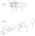
- the inventive device for damping a toilet seat or a toilet lid according to FIG. 1 has a first one Sleeve 1, a recorded in the sleeve damper 2 and a first end piece 3.
- the damper includes one Pin portion 4 and a cylinder portion 5, the at flattened his the journal portion opposite end is.
- the tail 3 has a bore 6, in the Fixing the device to a toilet bowl a the toilet bowl associated (not shown) mounting pin is pluggable. At its side facing the damper 3 carries the tail two web-like projections 7, the encompass flattened portion of the cylinder 5 and the Cylinder section thus holds in the circumferential direction. Between the sleeve 1 and the end piece 3, an O-ring 8 is arranged, which fixes the tail in the sleeve and an unwanted Slipping out prevented. As a rule, you will get the O-ring Arrange 8 in a the end piece 3 associated groove.
- FIG. 2 shows the damping device according to FIG. 1 in FIG a perspective exploded view.
- the damper 2 is first inserted into the sleeve 1. He comes with his pivot 4 in engagement with a complementary formed in the sleeve Receiving portion 9, which is formed as a radial slot which is a breakthrough to the interior of the sleeve creates. The pin 4 is thus always rotationally fixed with the sleeve 1 connected. Subsequently, the tail 3 together with the O-ring 8 inserted into the sleeve 1, in such a way that the two web-like projections 7 the flattened Embrace section of the cylinder 5. Alternatively is also one Inserting the end piece 3 together with already pre-assembled Damper 2 in the sleeve 1 possible. In any case, that is Assembling the device according to the invention very light.
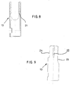
- FIGS 3 and 4 show a second embodiment the damping device according to the invention.
- the second Embodiment has an end piece 11, both of which Webs 12 now include the pin 4 of the damper 2.
- the Damper 2 is received in a sleeve 13 which in its End region has a recess 14 through which at plugged damper 2, the flattened portion of the Damper rotatably connected to the sleeve 13 is connected.
- the cylinder portion 5 of the rotates Damper 2, while the pin 4 through the end of the 11th is held.
- Figure 5 shows the first embodiment as left-side damping device and the second Embodiment as a right-side damping device.
- the first embodiment as left-side damping device and the second Embodiment as a right-side damping device.
- the second Embodiment stands at the left side Execution of the tail with the cylinder portion 5 in Intervention, while in the right-hand version of the Pin 4 is encompassed by the webs 12 of the tail.
- Only schematically indicated are two integral with a female seat 14 (not shown), 15 and two a (also not shown) toilet lid associated shots 16, 17. Both the seat and the Lid are in the closed position.
- the lid associated receptacle 17 in engagement with the sleeve 1.
- the sleeve 1 rotates (and with the sleeve 1 and the pin 4) with.
- the cylinder section 5 the damper 2 remains stationary.
- the assigned to the seat Recording 15 slides on a pivoting of the seat on the Sleeve 1 off.
- a great advantage of the invention is that the used damper 2 - and in particular their pin 4 - only be charged in the direction of rotation.
- the z. T. considerable Transverse forces are absorbed by the sleeve 1, 13 and over the end piece 3, 11 passed into the toilet bowl or ceramic.
- the life of the damper is comparable to comparable significantly increased in conventional constructions.
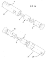
- Figures 6 and 7 show the sleeve 1 of the first Exemplary embodiment in isolation.
- assembled Condition is the (not shown here) damper on a Stop 18 (see Figure 6), wherein the pin of the Damper in the formed as a radial slot Receiving portion 9 of the sleeve 1 engages, the one Breakthrough creates the interior of the sleeve.
- the sleeve 1 has on its outer side a groove 19, the exact positioning of the sleeve - and thus the Damper - allowed.
- the groove 19 engages an associated in one of the recordings 15 or 17 trained web. It can also be provided several grooves / webs. Although you can the groove / webs with suitable training for transmission the torque required positive rotation engagement but their task is first Line in the positioning of the sleeve.
- the actual Engaging for power transmission creates a flat 20, through the trained as a radial slot Receiving section 9 is formed. In the flattening 20 engages (not shown) the toilet seat or toilet lid assigned web.
- Figures 8 and 9 show the sleeve of the second Exemplary embodiment in isolation.
- assembled Condition is the (not shown here) damper on a Stop 21 (see Figure 8), wherein the flattened part of the cylinder portion of the damper in as radial Slot formed receiving portion of the sleeve 13th engages a breakthrough to the interior of the sleeve creates.
- Stop 21 see Figure 8
- Nute 22 trained in the associated in one of Recordings 14 or 16 trained webs attack.
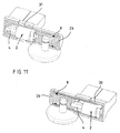
- Figure 10 shows a further pair of inventive Damping devices in a perspective Exploded view of another form of damper 2 is adjusted.
- the left side in the figure arranged on the left Damping device and the right side Damping device have identical end pieces 26.
- the both sleeves 27 and 28 are also with both sides formed open sleeve ends, wherein the sleeve 27 to the Pin 4 receives opposite portion of the damper, while the sleeve 28 defines the pin 4.
- grooves 29 are formed with Webs 30 (see Figure 11) are engaged. It will be the Steamed toilet lid. The recording associated with the toilet ring slides on a pivoting movement on the sleeve.
- Figure 11 shows both damping devices mounted.
- FIG. 12 in which in one Sectional view of an embodiment similar to the Figure 1 is shown.
- the damper 2 is received, wherein two webs 341 embrace the flattened portion of the cylinder 5.
- the Sleeve 33 is engaged with the pin 4 of the damper 2 and thus creates a non-rotatable connection.
- a groove 34 formed in a (not shown) retaining ring is used, the a sliding out of the unit of sleeve 33, damper 2 and End piece 32 from the receptacle of the (not shown) toilet seat or toilet lid prevented.
- the circlip is in one Recess in the toilet seat or in the toilet lid, preferably in Area of the joint, placed.
- a screw 35 provided radially in the tail is screwed in. From FIGS. 14 and 15 it becomes clear that the screw is accessible even when the end piece is inserted is, via a slot 36, which is inserted Mounting pin limits the rotational movement of the sleeve 33.
- the screw 35 is fixed to the Fastening pin screwed into the end piece so far, that the sleeve can slide freely on the tail.
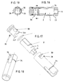
- Figures 16 to 19 show a the Embodiment according to FIGS 12 to 15 configured Embodiment, but in this case a right-sided Damping device.
- Figures 12 to 15 configured Embodiment, but in this case a right-sided Damping device.
- Reference numerals selected in Figures 12 to 15, and it becomes in this respect on the associated figure description directed.
- inventive device completely in the recording be integrated.
- the arrangement can be made that only the end of the tail is visible.
- the tail can be formed directly with a pin and e.g. via a bayonet-type closure with the sleeve get connected.
- the shown mounting hole corresponds however, as a rule.
- inventive Set up as both right- and left-sided Damping device can be used and is not on the illustrated form of the shots of the seat and lid limited.
Landscapes
- Health & Medical Sciences (AREA)
- Public Health (AREA)
- Toilet Supplies (AREA)
- Fluid-Damping Devices (AREA)
Applications Claiming Priority (2)
| Application Number | Priority Date | Filing Date | Title |
|---|---|---|---|
| DE10353944A DE10353944B4 (de) | 2003-11-18 | 2003-11-18 | Einrichtung zum Dämpfen eines WC-Sitzes oder eines WC-Deckels |
| DE10353944 | 2003-11-18 |
Publications (3)
| Publication Number | Publication Date |
|---|---|
| EP1532913A2 true EP1532913A2 (fr) | 2005-05-25 |
| EP1532913A3 EP1532913A3 (fr) | 2006-04-19 |
| EP1532913B1 EP1532913B1 (fr) | 2008-06-04 |
Family
ID=34428792
Family Applications (1)
| Application Number | Title | Priority Date | Filing Date |
|---|---|---|---|
| EP04027382A Expired - Lifetime EP1532913B1 (fr) | 2003-11-18 | 2004-11-18 | Dispositif d'amortissement de sièges de toilettes et/ou de couvercle de toilettes |
Country Status (3)
| Country | Link |
|---|---|
| EP (1) | EP1532913B1 (fr) |
| AT (1) | ATE397407T1 (fr) |
| DE (2) | DE10353944B4 (fr) |
Cited By (2)
| Publication number | Priority date | Publication date | Assignee | Title |
|---|---|---|---|---|
| WO2008151678A1 (fr) | 2007-06-13 | 2008-12-18 | Sipex Cavagna S.P.A. | Dispositif de freinage interposable entre des éléments solidaires en rotation |
| WO2012092930A2 (fr) | 2011-01-03 | 2012-07-12 | Pressalit A/S | Agencement de charnière de toilettes |
Families Citing this family (3)
| Publication number | Priority date | Publication date | Assignee | Title |
|---|---|---|---|---|
| DE102004029419B4 (de) * | 2004-06-18 | 2011-04-28 | Hamberger Industriewerke Gmbh | WC-Sitzgelenk und WC-Sitzgarnitur |
| DE112006004229B4 (de) * | 2006-08-16 | 2018-07-05 | Bestter (Xiamen) Technology Inc. | Eine Montagehalterung für Deckel und Sitz einer Toilettenschüssel |
| DE102019105939B4 (de) * | 2018-10-08 | 2022-06-30 | Hamberger Industriewerke Gmbh | Rotationsdämpfer und WC-Sitzgarnitur |
Citations (2)
| Publication number | Priority date | Publication date | Assignee | Title |
|---|---|---|---|---|
| DE3437138C2 (de) | 1984-10-10 | 1986-10-30 | Pag Presswerk Ag, 4300 Essen | Toilettenabdeckung mit Dämpfungselementen |
| DE10051805A1 (de) | 2000-10-18 | 2002-05-16 | Hamberger Industriewerke Gmbh | WC-Sitzgelenk |
Family Cites Families (3)
| Publication number | Priority date | Publication date | Assignee | Title |
|---|---|---|---|---|
| JP2003176845A (ja) * | 2001-12-12 | 2003-06-27 | Sankyo Seiki Mfg Co Ltd | ダンパー装置 |
| DE20215330U1 (de) * | 2002-04-23 | 2002-12-19 | ASEM Industrieberatung und Vermittlung GmbH, 41352 Korschenbroich | Befestigungsvorrichtung für die Absenkung einer Toilettenabdeckung mit Schnellbefestigung |
| DE10324172A1 (de) * | 2002-05-27 | 2003-12-11 | Mkw Iot Metall Kunststoff Und | Gelenk |
-
2003
- 2003-11-18 DE DE10353944A patent/DE10353944B4/de not_active Expired - Fee Related
-
2004
- 2004-11-18 AT AT04027382T patent/ATE397407T1/de not_active IP Right Cessation
- 2004-11-18 DE DE502004007312T patent/DE502004007312D1/de not_active Expired - Lifetime
- 2004-11-18 EP EP04027382A patent/EP1532913B1/fr not_active Expired - Lifetime
Patent Citations (2)
| Publication number | Priority date | Publication date | Assignee | Title |
|---|---|---|---|---|
| DE3437138C2 (de) | 1984-10-10 | 1986-10-30 | Pag Presswerk Ag, 4300 Essen | Toilettenabdeckung mit Dämpfungselementen |
| DE10051805A1 (de) | 2000-10-18 | 2002-05-16 | Hamberger Industriewerke Gmbh | WC-Sitzgelenk |
Cited By (4)
| Publication number | Priority date | Publication date | Assignee | Title |
|---|---|---|---|---|
| WO2008151678A1 (fr) | 2007-06-13 | 2008-12-18 | Sipex Cavagna S.P.A. | Dispositif de freinage interposable entre des éléments solidaires en rotation |
| CN101677726B (zh) * | 2007-06-13 | 2012-01-25 | 西派克斯卡瓦格纳股份公司 | 可置于可互相转动的元件之间的阻滞装置 |
| WO2012092930A2 (fr) | 2011-01-03 | 2012-07-12 | Pressalit A/S | Agencement de charnière de toilettes |
| WO2012092930A3 (fr) * | 2011-01-03 | 2013-09-12 | Pressalit A/S | Agencement de charnière de toilettes |
Also Published As
| Publication number | Publication date |
|---|---|
| ATE397407T1 (de) | 2008-06-15 |
| EP1532913A3 (fr) | 2006-04-19 |
| DE10353944B4 (de) | 2007-08-09 |
| EP1532913B1 (fr) | 2008-06-04 |
| DE10353944A1 (de) | 2005-06-23 |
| DE502004007312D1 (de) | 2008-07-17 |
Similar Documents
| Publication | Publication Date | Title |
|---|---|---|
| DE60012501T2 (de) | Federscharnierbauteil für brillenfassung | |
| EP1290303B1 (fr) | Serrure a barres pour systeme de fermeture | |
| DE102015106917B4 (de) | Möbelscharnier mit einem Dämpfer und einer Feder | |
| EP0599784A1 (fr) | Douille pour un terminal de connexion à fibre optique | |
| DE202008006909U1 (de) | Dämpfungseinrichtung für Möbeltüren | |
| DE20218927U1 (de) | Dämpfungs- und Einzugsvorrichtung für Schiebetüren | |
| DE102015106919A1 (de) | Möbelscharnier mit einem Dämpfer | |
| EP2587089A1 (fr) | Evaporateur pour un mouvement rotatif de couvercles et lunettes de toilettes | |
| EP1109983B1 (fr) | Charniere a visser comportant une position d'arret | |
| CH644666A5 (de) | Scharnier. | |
| EP0228527B1 (fr) | Ferrure pour portes et fenêtres | |
| DE10204766B4 (de) | Türscharnier für eine Fahrzeugtür | |
| EP1532913B1 (fr) | Dispositif d'amortissement de sièges de toilettes et/ou de couvercle de toilettes | |
| DE19932443C2 (de) | Scharnier | |
| DE2949962C2 (de) | Scharnier mit Schließmechanismus | |
| DE202011107194U1 (de) | Dämpfer für eine Drehbewegung von Toilettendeckeln und -brillen | |
| EP1659250B1 (fr) | Fenêtre, porte ou analogue avec un renvoi de coin | |
| DE10153709B4 (de) | Kabelkanalübergang zwischen einem Türflügel und einer Türzarge | |
| EP0662559B1 (fr) | Penture | |
| DE102007010930A1 (de) | Dämpfungseinrichtung | |
| EP4001555A1 (fr) | Poignée de commande avec conducteur de longueur variable | |
| DE102004041723B3 (de) | Scharnierschalter | |
| EP1134344B1 (fr) | Tourillon pour portes, fenêtres, volets ou similaires | |
| DE10060655B4 (de) | Verschlußvorrichtung | |
| EP0677631B2 (fr) | Actionneur pour une crémone |
Legal Events
| Date | Code | Title | Description |
|---|---|---|---|
| PUAI | Public reference made under article 153(3) epc to a published international application that has entered the european phase |
Free format text: ORIGINAL CODE: 0009012 |
|
| AK | Designated contracting states |
Kind code of ref document: A2 Designated state(s): AT BE BG CH CY CZ DE DK EE ES FI FR GB GR HU IE IS IT LI LU MC NL PL PT RO SE SI SK TR |
|
| AX | Request for extension of the european patent |
Extension state: AL HR LT LV MK YU |
|
| PUAL | Search report despatched |
Free format text: ORIGINAL CODE: 0009013 |
|
| AK | Designated contracting states |
Kind code of ref document: A3 Designated state(s): AT BE BG CH CY CZ DE DK EE ES FI FR GB GR HU IE IS IT LI LU MC NL PL PT RO SE SI SK TR |
|
| AX | Request for extension of the european patent |
Extension state: AL HR LT LV MK YU |
|
| 17P | Request for examination filed |
Effective date: 20060904 |
|
| AKX | Designation fees paid |
Designated state(s): AT BE BG CH CY CZ DE DK EE ES FI FR GB GR HU IE IS IT LI LU MC NL PL PT RO SE SI SK TR |
|
| GRAP | Despatch of communication of intention to grant a patent |
Free format text: ORIGINAL CODE: EPIDOSNIGR1 |
|
| GRAS | Grant fee paid |
Free format text: ORIGINAL CODE: EPIDOSNIGR3 |
|
| RAP1 | Party data changed (applicant data changed or rights of an application transferred) |
Owner name: PAGETTE GMBH |
|
| GRAA | (expected) grant |
Free format text: ORIGINAL CODE: 0009210 |
|
| AK | Designated contracting states |
Kind code of ref document: B1 Designated state(s): AT BE BG CH CY CZ DE DK EE ES FI FR GB GR HU IE IS IT LI LU MC NL PL PT RO SE SI SK TR |
|
| REG | Reference to a national code |
Ref country code: GB Ref legal event code: FG4D Free format text: NOT ENGLISH |
|
| REG | Reference to a national code |
Ref country code: CH Ref legal event code: EP |
|
| REF | Corresponds to: |
Ref document number: 502004007312 Country of ref document: DE Date of ref document: 20080717 Kind code of ref document: P |
|
| REG | Reference to a national code |
Ref country code: IE Ref legal event code: FG4D Free format text: LANGUAGE OF EP DOCUMENT: GERMAN |
|
| PG25 | Lapsed in a contracting state [announced via postgrant information from national office to epo] |
Ref country code: ES Free format text: LAPSE BECAUSE OF FAILURE TO SUBMIT A TRANSLATION OF THE DESCRIPTION OR TO PAY THE FEE WITHIN THE PRESCRIBED TIME-LIMIT Effective date: 20080915 Ref country code: FI Free format text: LAPSE BECAUSE OF FAILURE TO SUBMIT A TRANSLATION OF THE DESCRIPTION OR TO PAY THE FEE WITHIN THE PRESCRIBED TIME-LIMIT Effective date: 20080604 Ref country code: SI Free format text: LAPSE BECAUSE OF FAILURE TO SUBMIT A TRANSLATION OF THE DESCRIPTION OR TO PAY THE FEE WITHIN THE PRESCRIBED TIME-LIMIT Effective date: 20080604 |
|
| PG25 | Lapsed in a contracting state [announced via postgrant information from national office to epo] |
Ref country code: PL Free format text: LAPSE BECAUSE OF FAILURE TO SUBMIT A TRANSLATION OF THE DESCRIPTION OR TO PAY THE FEE WITHIN THE PRESCRIBED TIME-LIMIT Effective date: 20080604 |
|
| NLT1 | Nl: modifications of names registered in virtue of documents presented to the patent office pursuant to art. 16 a, paragraph 1 |
Owner name: TOTO GERMANY GMBH |
|
| REG | Reference to a national code |
Ref country code: IE Ref legal event code: FD4D |
|
| PG25 | Lapsed in a contracting state [announced via postgrant information from national office to epo] |
Ref country code: IS Free format text: LAPSE BECAUSE OF FAILURE TO SUBMIT A TRANSLATION OF THE DESCRIPTION OR TO PAY THE FEE WITHIN THE PRESCRIBED TIME-LIMIT Effective date: 20081004 Ref country code: CZ Free format text: LAPSE BECAUSE OF FAILURE TO SUBMIT A TRANSLATION OF THE DESCRIPTION OR TO PAY THE FEE WITHIN THE PRESCRIBED TIME-LIMIT Effective date: 20080604 Ref country code: IE Free format text: LAPSE BECAUSE OF FAILURE TO SUBMIT A TRANSLATION OF THE DESCRIPTION OR TO PAY THE FEE WITHIN THE PRESCRIBED TIME-LIMIT Effective date: 20080604 Ref country code: SE Free format text: LAPSE BECAUSE OF FAILURE TO SUBMIT A TRANSLATION OF THE DESCRIPTION OR TO PAY THE FEE WITHIN THE PRESCRIBED TIME-LIMIT Effective date: 20080904 Ref country code: PT Free format text: LAPSE BECAUSE OF FAILURE TO SUBMIT A TRANSLATION OF THE DESCRIPTION OR TO PAY THE FEE WITHIN THE PRESCRIBED TIME-LIMIT Effective date: 20081104 |
|
| RAP2 | Party data changed (patent owner data changed or rights of a patent transferred) |
Owner name: TOTO GERMANY GMBH |
|
| PG25 | Lapsed in a contracting state [announced via postgrant information from national office to epo] |
Ref country code: SK Free format text: LAPSE BECAUSE OF FAILURE TO SUBMIT A TRANSLATION OF THE DESCRIPTION OR TO PAY THE FEE WITHIN THE PRESCRIBED TIME-LIMIT Effective date: 20080604 Ref country code: RO Free format text: LAPSE BECAUSE OF FAILURE TO SUBMIT A TRANSLATION OF THE DESCRIPTION OR TO PAY THE FEE WITHIN THE PRESCRIBED TIME-LIMIT Effective date: 20080604 |
|
| PLBE | No opposition filed within time limit |
Free format text: ORIGINAL CODE: 0009261 |
|
| STAA | Information on the status of an ep patent application or granted ep patent |
Free format text: STATUS: NO OPPOSITION FILED WITHIN TIME LIMIT |
|
| PG25 | Lapsed in a contracting state [announced via postgrant information from national office to epo] |
Ref country code: BG Free format text: LAPSE BECAUSE OF FAILURE TO SUBMIT A TRANSLATION OF THE DESCRIPTION OR TO PAY THE FEE WITHIN THE PRESCRIBED TIME-LIMIT Effective date: 20080904 Ref country code: DK Free format text: LAPSE BECAUSE OF FAILURE TO SUBMIT A TRANSLATION OF THE DESCRIPTION OR TO PAY THE FEE WITHIN THE PRESCRIBED TIME-LIMIT Effective date: 20080604 Ref country code: EE Free format text: LAPSE BECAUSE OF FAILURE TO SUBMIT A TRANSLATION OF THE DESCRIPTION OR TO PAY THE FEE WITHIN THE PRESCRIBED TIME-LIMIT Effective date: 20080604 |
|
| NLT2 | Nl: modifications (of names), taken from the european patent patent bulletin |
Owner name: TOTO GERMANY GMBH Effective date: 20090218 |
|
| 26N | No opposition filed |
Effective date: 20090305 |
|
| REG | Reference to a national code |
Ref country code: FR Ref legal event code: CD |
|
| BERE | Be: lapsed |
Owner name: PAGETTE G.M.B.H. Effective date: 20081130 |
|
| PG25 | Lapsed in a contracting state [announced via postgrant information from national office to epo] |
Ref country code: MC Free format text: LAPSE BECAUSE OF NON-PAYMENT OF DUE FEES Effective date: 20081130 |
|
| REG | Reference to a national code |
Ref country code: CH Ref legal event code: PL |
|
| PG25 | Lapsed in a contracting state [announced via postgrant information from national office to epo] |
Ref country code: BE Free format text: LAPSE BECAUSE OF NON-PAYMENT OF DUE FEES Effective date: 20081130 |
|
| PG25 | Lapsed in a contracting state [announced via postgrant information from national office to epo] |
Ref country code: LI Free format text: LAPSE BECAUSE OF NON-PAYMENT OF DUE FEES Effective date: 20081130 Ref country code: CH Free format text: LAPSE BECAUSE OF NON-PAYMENT OF DUE FEES Effective date: 20081130 |
|
| PG25 | Lapsed in a contracting state [announced via postgrant information from national office to epo] |
Ref country code: AT Free format text: LAPSE BECAUSE OF NON-PAYMENT OF DUE FEES Effective date: 20081118 |
|
| PG25 | Lapsed in a contracting state [announced via postgrant information from national office to epo] |
Ref country code: CY Free format text: LAPSE BECAUSE OF FAILURE TO SUBMIT A TRANSLATION OF THE DESCRIPTION OR TO PAY THE FEE WITHIN THE PRESCRIBED TIME-LIMIT Effective date: 20080604 Ref country code: LU Free format text: LAPSE BECAUSE OF NON-PAYMENT OF DUE FEES Effective date: 20081118 Ref country code: HU Free format text: LAPSE BECAUSE OF FAILURE TO SUBMIT A TRANSLATION OF THE DESCRIPTION OR TO PAY THE FEE WITHIN THE PRESCRIBED TIME-LIMIT Effective date: 20081205 |
|
| PG25 | Lapsed in a contracting state [announced via postgrant information from national office to epo] |
Ref country code: TR Free format text: LAPSE BECAUSE OF FAILURE TO SUBMIT A TRANSLATION OF THE DESCRIPTION OR TO PAY THE FEE WITHIN THE PRESCRIBED TIME-LIMIT Effective date: 20080604 |
|
| PG25 | Lapsed in a contracting state [announced via postgrant information from national office to epo] |
Ref country code: GR Free format text: LAPSE BECAUSE OF FAILURE TO SUBMIT A TRANSLATION OF THE DESCRIPTION OR TO PAY THE FEE WITHIN THE PRESCRIBED TIME-LIMIT Effective date: 20080905 |
|
| PGFP | Annual fee paid to national office [announced via postgrant information from national office to epo] |
Ref country code: FR Payment date: 20101130 Year of fee payment: 7 |
|
| PGFP | Annual fee paid to national office [announced via postgrant information from national office to epo] |
Ref country code: IT Payment date: 20101125 Year of fee payment: 7 Ref country code: GB Payment date: 20101118 Year of fee payment: 7 |
|
| GBPC | Gb: european patent ceased through non-payment of renewal fee |
Effective date: 20111118 |
|
| REG | Reference to a national code |
Ref country code: FR Ref legal event code: ST Effective date: 20120731 |
|
| PG25 | Lapsed in a contracting state [announced via postgrant information from national office to epo] |
Ref country code: IT Free format text: LAPSE BECAUSE OF NON-PAYMENT OF DUE FEES Effective date: 20111118 |
|
| PG25 | Lapsed in a contracting state [announced via postgrant information from national office to epo] |
Ref country code: GB Free format text: LAPSE BECAUSE OF NON-PAYMENT OF DUE FEES Effective date: 20111118 |
|
| PG25 | Lapsed in a contracting state [announced via postgrant information from national office to epo] |
Ref country code: FR Free format text: LAPSE BECAUSE OF NON-PAYMENT OF DUE FEES Effective date: 20111130 |
|
| PGFP | Annual fee paid to national office [announced via postgrant information from national office to epo] |
Ref country code: DE Payment date: 20151130 Year of fee payment: 12 |
|
| PGFP | Annual fee paid to national office [announced via postgrant information from national office to epo] |
Ref country code: NL Payment date: 20151118 Year of fee payment: 12 |
|
| REG | Reference to a national code |
Ref country code: DE Ref legal event code: R119 Ref document number: 502004007312 Country of ref document: DE |
|
| REG | Reference to a national code |
Ref country code: NL Ref legal event code: MM Effective date: 20161201 |
|
| PG25 | Lapsed in a contracting state [announced via postgrant information from national office to epo] |
Ref country code: NL Free format text: LAPSE BECAUSE OF NON-PAYMENT OF DUE FEES Effective date: 20161201 |
|
| PG25 | Lapsed in a contracting state [announced via postgrant information from national office to epo] |
Ref country code: DE Free format text: LAPSE BECAUSE OF NON-PAYMENT OF DUE FEES Effective date: 20170601 |