EP1533035A1 - Porte-échantillon - Google Patents
Porte-échantillon Download PDFInfo
- Publication number
- EP1533035A1 EP1533035A1 EP04026639A EP04026639A EP1533035A1 EP 1533035 A1 EP1533035 A1 EP 1533035A1 EP 04026639 A EP04026639 A EP 04026639A EP 04026639 A EP04026639 A EP 04026639A EP 1533035 A1 EP1533035 A1 EP 1533035A1
- Authority
- EP
- European Patent Office
- Prior art keywords
- sample
- liquid
- sample carrier
- carrier according
- memory
- Prior art date
- Legal status (The legal status is an assumption and is not a legal conclusion. Google has not performed a legal analysis and makes no representation as to the accuracy of the status listed.)
- Withdrawn
Links
Images

Classifications
-
- B—PERFORMING OPERATIONS; TRANSPORTING
- B01—PHYSICAL OR CHEMICAL PROCESSES OR APPARATUS IN GENERAL
- B01L—CHEMICAL OR PHYSICAL LABORATORY APPARATUS FOR GENERAL USE
- B01L3/00—Containers or dishes for laboratory use, e.g. laboratory glassware; Droppers
- B01L3/50—Containers for the purpose of retaining a material to be analysed, e.g. test tubes
- B01L3/502—Containers for the purpose of retaining a material to be analysed, e.g. test tubes with fluid transport, e.g. in multi-compartment structures
- B01L3/5027—Containers for the purpose of retaining a material to be analysed, e.g. test tubes with fluid transport, e.g. in multi-compartment structures by integrated microfluidic structures, i.e. dimensions of channels and chambers are such that surface tension forces are important, e.g. lab-on-a-chip
- B01L3/502723—Containers for the purpose of retaining a material to be analysed, e.g. test tubes with fluid transport, e.g. in multi-compartment structures by integrated microfluidic structures, i.e. dimensions of channels and chambers are such that surface tension forces are important, e.g. lab-on-a-chip characterised by venting arrangements
-
- B—PERFORMING OPERATIONS; TRANSPORTING
- B01—PHYSICAL OR CHEMICAL PROCESSES OR APPARATUS IN GENERAL
- B01L—CHEMICAL OR PHYSICAL LABORATORY APPARATUS FOR GENERAL USE
- B01L2200/00—Solutions for specific problems relating to chemical or physical laboratory apparatus
- B01L2200/02—Adapting objects or devices to another
- B01L2200/026—Fluid interfacing between devices or objects, e.g. connectors, inlet details
-
- B—PERFORMING OPERATIONS; TRANSPORTING
- B01—PHYSICAL OR CHEMICAL PROCESSES OR APPARATUS IN GENERAL
- B01L—CHEMICAL OR PHYSICAL LABORATORY APPARATUS FOR GENERAL USE
- B01L2200/00—Solutions for specific problems relating to chemical or physical laboratory apparatus
- B01L2200/14—Process control and prevention of errors
- B01L2200/142—Preventing evaporation
-
- B—PERFORMING OPERATIONS; TRANSPORTING
- B01—PHYSICAL OR CHEMICAL PROCESSES OR APPARATUS IN GENERAL
- B01L—CHEMICAL OR PHYSICAL LABORATORY APPARATUS FOR GENERAL USE
- B01L2300/00—Additional constructional details
- B01L2300/08—Geometry, shape and general structure
- B01L2300/0809—Geometry, shape and general structure rectangular shaped
- B01L2300/0825—Test strips
-
- B—PERFORMING OPERATIONS; TRANSPORTING
- B01—PHYSICAL OR CHEMICAL PROCESSES OR APPARATUS IN GENERAL
- B01L—CHEMICAL OR PHYSICAL LABORATORY APPARATUS FOR GENERAL USE
- B01L2300/00—Additional constructional details
- B01L2300/08—Geometry, shape and general structure
- B01L2300/0861—Configuration of multiple channels and/or chambers in a single devices
- B01L2300/087—Multiple sequential chambers
-
- B—PERFORMING OPERATIONS; TRANSPORTING
- B01—PHYSICAL OR CHEMICAL PROCESSES OR APPARATUS IN GENERAL
- B01L—CHEMICAL OR PHYSICAL LABORATORY APPARATUS FOR GENERAL USE
- B01L2400/00—Moving or stopping fluids
- B01L2400/04—Moving fluids with specific forces or mechanical means
- B01L2400/0403—Moving fluids with specific forces or mechanical means specific forces
- B01L2400/0406—Moving fluids with specific forces or mechanical means specific forces capillary forces
-
- B—PERFORMING OPERATIONS; TRANSPORTING
- B01—PHYSICAL OR CHEMICAL PROCESSES OR APPARATUS IN GENERAL
- B01L—CHEMICAL OR PHYSICAL LABORATORY APPARATUS FOR GENERAL USE
- B01L2400/00—Moving or stopping fluids
- B01L2400/06—Valves, specific forms thereof
- B01L2400/0688—Valves, specific forms thereof surface tension valves, capillary stop, capillary break
-
- B—PERFORMING OPERATIONS; TRANSPORTING
- B01—PHYSICAL OR CHEMICAL PROCESSES OR APPARATUS IN GENERAL
- B01L—CHEMICAL OR PHYSICAL LABORATORY APPARATUS FOR GENERAL USE
- B01L3/00—Containers or dishes for laboratory use, e.g. laboratory glassware; Droppers
- B01L3/50—Containers for the purpose of retaining a material to be analysed, e.g. test tubes
- B01L3/502—Containers for the purpose of retaining a material to be analysed, e.g. test tubes with fluid transport, e.g. in multi-compartment structures
- B01L3/5027—Containers for the purpose of retaining a material to be analysed, e.g. test tubes with fluid transport, e.g. in multi-compartment structures by integrated microfluidic structures, i.e. dimensions of channels and chambers are such that surface tension forces are important, e.g. lab-on-a-chip
- B01L3/502738—Containers for the purpose of retaining a material to be analysed, e.g. test tubes with fluid transport, e.g. in multi-compartment structures by integrated microfluidic structures, i.e. dimensions of channels and chambers are such that surface tension forces are important, e.g. lab-on-a-chip characterised by integrated valves
Definitions
- the present invention relates to a sample carrier according to the preamble of claim 1 and a use of the sample carrier.
- sample chambers are in one Base plate introduced on one side, so open to a flat side.
- the sample chambers are filled with reagents covered a foil.
- reagents covered a foil.
- For chemical or biological diagnosis is a Sample liquid filled in a sample holder by means of a pipette or sucked in, for example by capillary forces.
- the sample liquid flows then automatically due to capillary forces via a distribution channel and Inlet channels into the sample chambers.
- the sample liquid reacts in the sample chambers with the previously introduced reagents.
- the reactions will be for example, optically detected.
- the sample holder can also after the first filling with sample liquid be closed again by an additional foil to minimize evaporation.
- the present invention is based on the object, a sample carrier and to indicate its use, even with a long residence time of sample liquid in the sample carrier, especially long-lasting reactions, and / or can be used at high temperatures without refilling of sample liquid In particular, wherein covering the sample receptacle after the first application of sample liquid is not required.
- One aspect of the present invention is in addition to the sample carrier provided with a covered storage for sample liquid, so that during evaporation or other loss or consumption of sample liquid new sample liquid from the memory in the distribution channel and / or the sample chamber (s) can flow, the memory in the filled state and during its discharge via a connection channel with the Environment communicating through the sample liquid or a other liquid is kept closed in such a way, if necessary Sucking in or flowing in from the atmosphere surrounding the sample carrier, especially air, to allow the emptying of the memory, however to limit or prevent the free opposite gas exchange.
- the connecting channel is itself by capillary forces automatically closing liquid closure formed. This allows for easy Construction easy handling.
- the memory is preferably in the form of an additional chamber.
- the memory may also be extended or additional, preferably tortuous and / or in cross section be formed enlarged portion of a distribution channel to which the sample chamber are connected. This allows a simple, inexpensive each Construction.
- the sample liquid on the sample carrier is exclusive transported by capillary forces to the desired locations.
- the Transport of the sample liquid alternatively by other mechanisms or not exclusively by capillary forces.
- Fig. 1 shows a schematic, partial plan view of a first Embodiment of a proposed sample carrier 1 - also microtiter plate called - with cavities 2 in the ⁇ l range, namely at least one Sample holder 3 for sample liquid 4 and preferably several over a common distribution channel 5 connected to the sample holder 3 Sample chambers 6.
- the sample carrier 1 can carry a plurality of sample receptacles 3 in each case at least one distribution channel 5 connected thereto and assigned Have sample chambers 6.
- the cavities are 2 except for the sample receptacle 3 covered by a particular film-like cover 7, preferably completed on the top side. So one becomes at least essentially closed or largely protected against evaporation line system formed for the sample liquid 4.
- sample liquid 4 is already in the sample receptacle 3 filled or applied, but not yet connected to the Cavities 2 streamed.
- the filling of sample liquid 4 is at the first Embodiment problem-free, since the sample holder 3 after is open at the top, especially since they do not cover the cover 7 or optionally only partially covered. If necessary, the sample holder 3 is laterally closed, in particular cup-shaped or chamber-like design.
- the sample carrier 1 also has a memory 8 according to the proposal, in the first embodiment, the inlet side via a connecting channel 9 connected to the sample holder 3 and the outlet side to the distribution channel 5 is.
- the memory 8 is formed here näpfchen- or chamber-like and also covered by the cover 7.
- the sample liquid 4 can pass through the connecting channel 9, the memory 8, the distribution channel 5 and connected thereto inlet channels 10 flow into the sample chambers 6. This is preferably done automatically by capillary forces.
- venting channels 11 which in turn - In particular via an enlarged cross section connecting portion and / or a vent collecting channel 12 - in an outward open vent opening 13 open to those of the incoming sample liquid 4 displaced air or other atmosphere from the piping system derive.
- FIG. 2 shows a schematic longitudinal section of the sample carrier 1 according to FIG. 1 along channels 9, 5, 10, 11 and 12, but in a state in which the Sample liquid 4 from the sample holder 3 in the connected cavities 2 has flowed.
- the sample liquid 4 preferably does not flow in the illustrated embodiment from the sample chambers 6 in the venting channels 11, in particular because of appropriate training or cross-sectional differences each one so-called liquid stop 14 is formed. By capillary forces and / or Gravity, the sample liquid 4 is prevented from entering the ventilation channels 11 to flow.
- liquid stops 14 can only at the transition of the venting channels 11 in the vent collecting channel 12 - in particular by the in cross-section enlarged connecting portion - be formed, as shown in FIG. 2 indicated.
- liquid stops 14 may also not shown Valves or other suitable means for manipulating the Sample liquid 4 are used.
- the sample liquid 4 also be pumped, sucked or promoted by other effects.
- all cavities 2 are in a base body 15 of the sample carrier 1 formed.
- all cavities 2 are starting from a flat side 16 of the main body 15 and the flat side 16 open towards, for example by wells, grooves, grooves, recesses or the like.
- the cover 7 is glued to the base body 15 or its flat side 16, laminated or applied in any other way and covers all Cavities 2 - in the first embodiment with the exception of the sample holder 3 - of the sample carrier 1, so that the cavities 2 also closed at the top are as indicated in Fig. 1 and 2.
- the sample carrier 1 is thus preferably formed in two parts.
- sample carrier 1 can also be formed in one piece or several, optionally have separately applied covers 7.
- cover 7 instead of the preferred film-like design of the cover 7 can This example, by a glass plate or other suitable material be formed with suitable properties with a suitable shape.
- sample chambers 6 can after the flow of sample liquid 4 measurements, manipulations, examinations or reactions, for example for biological, in particular microbiological, or chemical Diagnostics, take place, in particular with or through in the sample chambers. 6 located, not shown reagents or by other action.
- the reagents are prior to applying the cover 7 in the Sample chambers 6 introduced.
- the cover 7 and / or the base body 15 preferably sufficient made of transparent material or preferably at least in regions, in particular above and / or below the sample chambers 6, transparent educated.
- sample liquid 4 from the sample holder 3 unhindered evaporate, especially if, as previously customary, no memory 8 is provided and Sample liquid 4 as evaporation reservoir in the sample holder 3 is still present after filling the sample chambers 6.
- the evaporation causes a refilling of sample liquid 4 in the sample holder 3 is usually required.
- the sample holder 1 additionally has the storage 8 for sample liquid 4 on.
- the storage 8 for sample liquid 4 can accordingly new sample liquid 4 from the memory 8 in the distribution channel 5 and in the sample chambers 6 flow and / or flow back into the connecting channel 9.
- the memory 8 is due to its arrangement - serially between the sample holder 3 and the sample chambers 6 - only before the sample chambers 6 can be filled with sample liquid 4.
- the proposed sample carrier 1 is preferably such - in particular by appropriate choice of the cross sections of the channels 5, 10, 11, 9 and / or appropriate training of the transitions between these and the chambers 3, 6, 8 - formed, that starting from the filled with sample liquid 4 Condition - so filled sample chambers 6 - in evaporation or otherwise Loss or consumption of sample liquid 4 a draining first Sampling 3 takes place, if not done at this time is, and then the memory 8 and then the distribution channel. 5 and the inlet channels 10, in particular so that up to this emptying the Sample chambers 6 remain filled with sample liquid 4. This can be special be achieved in that by correspondingly high capillary forces and / or valves not shown a retreat of the sample liquid. 4 from the sample chambers 6 and from the liquid stops 14 during the aforementioned emptying process is prevented.
- the sample carrier 1 is designed such that always - even during the Emptying of the memory 8 - sample liquid 4 in the connecting channel 9 is or pulled in by capillary forces, so that the connecting channel 9 at least temporarily or at least substantially constantly of sample liquid 4 is kept closed, as indicated in Fig. 2.
- the Closure of the connecting channel 9 by sample liquid 4 can also be characterized take place that sample liquid 4 only the opening into the memory 8 Inlet opening of the connecting channel 9 - the connecting channel 9 so only memory side - closes.
- the connection channel 9 remains until to the inlet end - ie to the opening to the sample holder 3 out, in particular up to a liquid stop 14 formed there - with sample liquid 4 filled or automatically refillable from the memory 8 from.
- the so formed liquid closure causes the ambient atmosphere through only flow or sucked into the connecting channel 9 in the memory and another gas exchange between the surface O the sample liquid 4 in the memory 8 and the environment is prevented.
- sample liquid 4 even in falling level in memory 8 - ie emptying of the memory 8 - ascend to the connecting channel 9 and close it can, is preferably a - later explained in more detail - capillary force generating device 17 provided, the sample liquid 4 from let the memory 8 ascend to the connection channel 9.
- the sample carrier 1 is then designed such that always sample liquid 4 from the memory. 8 is drawn to the connection channel 9 or in this, as long as Sample liquid 4 is present in the memory 8.
- a sample liquid amount of the Separate in the memory 8 located sample liquid 4 and the desired Create closure of the connecting channel 9, in which case preferably a further, not shown storage for sample liquid 4 the connection channel 9 to compensate for evaporation losses and maintenance associated with the fluid closure.
- connection channel 9 by sample liquid 4 results in that only the liquid surface in the connecting channel 9, but not the entire surface O of the sample liquid 4 in the memory 8 or its Base area, in particular by a factor of 10, 100 or even 1000 larger as the cross-sectional area of the connecting channel 9 is or are, with the Environment is in gas exchange and therefore subject to evaporation. Accordingly, the liquid closure leads to a substantially reduced Evaporation, since the surface O of the sample liquid 4 in memory 8 is not in gas exchange with the environment.
- the liquid closure When emptying the memory 8, the liquid closure remains at least in Maintained constantly and leaves at a corresponding negative pressure in the Memory 8 only (briefly) ambient atmosphere or air in the Flow memory 8 for venting or pressure equalization. By capillary force: then an immediate closing takes place again.
- the liquid closure acts Accordingly, as a one-way valve and prevents or inhibits at least the Gas exchange between the memory 8 and the environment.
- the liquid closure provides a particularly preferred, simple and inexpensive to be implemented solution. If necessary, instead of sample liquid 4 also another liquid, for example a control liquid, be used. This is particularly advantageous if only a little or not enough sample liquid 4 is available. alternative or additionally, instead of a liquid closure also another Valve, in particular a suitable one-way valve can be used.
- the Memory 8 has a smaller opening area for supplying sample liquid 4 and / or for ventilation or venting, in particular in the region of a liquid stop 14, as the distribution channel 5 on.
- the receiving volume of the storage 8 for sample liquid 4 at least 5%, preferably at least 10%, in particular at least 20%, of the receiving volume of the connected, sample liquid 4 receiving cavities 2, the sample holder 3 and / or all connected Sample chambers 6.
- the receiving volume of the sample holder 3 is substantially equal to or smaller than the sum of the recording volumes of the connected Cavities 2, in particular of the distribution channel 5, the connecting channel 9, the memory 8, the sample chambers 6 and / or the inlet channels 10 and / or optionally the venting channels 11, in particular so that after filling the sample holder 3 with sample liquid 4 this amount is received directly from the connected cavities 2, and preferably automatically by capillary forces, as already mentioned.
- sample liquid 4 preferably flows out of the reservoir 8 automatically, in particular by capillary forces, in subordinate or connected, Sample liquid 4 receiving cavities 2, such as the distribution channel 5, the inlet channels 10 and the sample chambers 6 and possibly the venting channels 11th
- the memory 8 is preferably only after the time Sample holder 3 can be emptied.
- the distribution channel 5 and / or the inlet channels 10 preferably emptied only after the memory 8.
- each sample receptacle is 3 and / or each distribution channel 5 preferably only a single memory 8 assigned.
- each distribution channel 5 preferably only a single memory 8 assigned.
- sample chambers 6 sample liquid 4 from the same memory 8 can be fed.
- further memory 8 may be provided be so that the sample chambers 6 group or individually the memory. 8 can be assigned.
- the sample chambers 6 are fluidically between the memory 8 and the downstream liquid stops 14 or not shown, for example Valves arranged.
- the desired flow cause the sample liquid 4 have the sample holder 3 and the memory 8 and optionally the sample chambers 6 preferably each Capillary force generating devices 17 in the range of their vertical Walls on.
- These capillary force generating devices 17 preferably have each a vertical groove or keyway with such Wedge angle on that the sample liquid 4 descend or rise by capillary forces and in the connecting channel 9, the distribution channel 5 and / or optionally can flow into the venting channels 11.
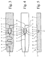
- FIG. 3 shows a second embodiment in a plan view corresponding to FIG. 1 of the sample carrier 1.
- the cover 7 here all cavities 2, including the sample holder 3 and, where appropriate, further sample receptacles 3 and other Cavities 2 of the sample carrier 1, if present.
- Cover 7 in the region of the sample holder 3 pre-scored, perforated, cut, weakened or provided with any other predetermined breaking point.
- the Cover 7 is accordingly partially in the area of the sample holder 3 opened or opened, so that here also a relatively high Evaporation of sample liquid 4 from the sample holder 3 occur can.
- the recorded from the memory 8 sample 4 is subject to contrast a much lower evaporation, so that by means of the memory 8 again - as in the first embodiment - a refilling of Sample liquid 4 in the sample holder 3 even with very long residence times of sample liquid 4 in the sample chambers 6 and / or high Temperatures can be avoided.
- the memory 8 is not chamber-shaped, but by a preferably additional, in particular meandering wound portion 18 of the distribution channel 5 is formed.
- the section 18 at least partially a relative to the distribution channel 5 enlarged cross-section to to achieve a sufficient storage volume, where appropriate, a corresponding capillary force generating device 17 on and / or outlet side is provided or are.
- Figs. 4 and 5 the sample liquid 4 and the cover 7 are off Simplification reasons omitted, wherein Fig. 4 corresponds to Fig. 1 and 3 corresponding Top view shows.
- the memory 8 is connected to the distribution channel 5 parallel to the sample chambers 6.
- the memory 8 after the sample chambers 6 and their feed channels 10 or connected to these at the end of the distribution channel 5 to this in particular so that the memory 8 only after the sample chambers. 6 can be filled with sample liquid 4, to first a fast filling of the sample chambers 6 with sample liquid 4 to allow.
- the memory 8 is again preferable cupped or chamber-like design.
- the memory 8 is or venting via a further connecting channel 19 to the vent collecting channel 12 connected.
- a further connecting channel 19 to the vent collecting channel 12 connected.
- this further Connecting channel 19 and the memory 8 or the vent collecting channel 12 is a liquid stop 14 and / or a liquid seal already formed sense explained in connection with the first embodiment, so that the sample liquid 4 is not from the memory 8 in the vent collecting channel 12 flows or the evaporation of sample liquid. 4 from the memory 8 - even during its emptying - is prevented.
- FIG. 5 of the sample carrier 1 according to FIG. 4 illustrates the structure and the formation of the cavities 2 in the main body 15th
- capillary force generating devices 17 provided, in particular in the memory 8 to the other connection channel 19 out.
- the sample holder 3 is preferably laterally open trained and forms in particular with appropriate Kochdekkung through the cover, not shown, a suction, the sample liquid 4, for example, blood directly from the finger of a person to be examined Person, preferably automatically by capillary forces in the sample carrier 1 can suck.
- the proposed sample carrier 1 is preferably for the particular microbiological diagnostics used, the sample chambers 6 with Sample liquid 4 filled and taking place in the sample chambers 6 reactions and / or related investigations or diagnostic measurements be automatically analyzed or performed, in particular of automated analyzers and / or in particular over several hours, preferably at about 37 ° C, without refilling of sample liquid 4.
Landscapes
- Chemical & Material Sciences (AREA)
- Health & Medical Sciences (AREA)
- Dispersion Chemistry (AREA)
- Analytical Chemistry (AREA)
- General Health & Medical Sciences (AREA)
- Hematology (AREA)
- Clinical Laboratory Science (AREA)
- Chemical Kinetics & Catalysis (AREA)
- Automatic Analysis And Handling Materials Therefor (AREA)
- Sampling And Sample Adjustment (AREA)
Applications Claiming Priority (2)
| Application Number | Priority Date | Filing Date | Title |
|---|---|---|---|
| DE10354806 | 2003-11-21 | ||
| DE10354806A DE10354806A1 (de) | 2003-11-21 | 2003-11-21 | Probenträger |
Publications (1)
| Publication Number | Publication Date |
|---|---|
| EP1533035A1 true EP1533035A1 (fr) | 2005-05-25 |
Family
ID=34428878
Family Applications (1)
| Application Number | Title | Priority Date | Filing Date |
|---|---|---|---|
| EP04026639A Withdrawn EP1533035A1 (fr) | 2003-11-21 | 2004-11-10 | Porte-échantillon |
Country Status (5)
| Country | Link |
|---|---|
| US (1) | US7829027B2 (fr) |
| EP (1) | EP1533035A1 (fr) |
| JP (1) | JP4921706B2 (fr) |
| CN (1) | CN1664543B (fr) |
| DE (1) | DE10354806A1 (fr) |
Cited By (2)
| Publication number | Priority date | Publication date | Assignee | Title |
|---|---|---|---|---|
| DE102006025477A1 (de) * | 2006-05-30 | 2007-12-06 | Ekf - Diagnostic Gmbh | Küvette |
| WO2008128534A1 (fr) * | 2007-04-24 | 2008-10-30 | Analytik Jena Ag | Cuvette pour l'analyse optique de petits volumes |
Families Citing this family (15)
| Publication number | Priority date | Publication date | Assignee | Title |
|---|---|---|---|---|
| DE102005054923B3 (de) | 2005-11-17 | 2007-04-12 | Siemens Ag | Vorrichtung und Verfahren zur Aufbereitung einer Probe |
| AU2006315037C1 (en) * | 2005-11-18 | 2013-05-02 | Ichnos Sciences SA | Anti-alpha2 integrin antibodies and their uses |
| KR100878229B1 (ko) | 2007-11-22 | 2009-01-12 | 주식회사 디지탈바이오테크놀러지 | 유체분석용 칩 |
| US8511889B2 (en) * | 2010-02-08 | 2013-08-20 | Agilent Technologies, Inc. | Flow distribution mixer |
| JP2014503426A (ja) * | 2010-11-10 | 2014-02-13 | ベーリンガー インゲルハイム マイクロパーツ ゲゼルシャフト ミット ベシュレンクテル ハフツング | ブリスタ包装材に液体を充填する方法及び液体を充填するためのキャビティを備えたブリスタ包装材 |
| CN102350379A (zh) * | 2011-07-04 | 2012-02-15 | 大连理工大学 | 一种基于自然沉积的填充柱的微流控全血预处理芯片 |
| WO2013168076A1 (fr) | 2012-05-11 | 2013-11-14 | Koninklijke Philips N.V. | Appareil d'imagerie ultrasonore et procédé d'imagerie ultrasonore d'un objet spéculaire et d'une anatomie cible dans un tissu |
| CN104870092A (zh) | 2012-11-29 | 2015-08-26 | 皇家飞利浦有限公司 | 用于样本的摄取和处理的盒 |
| JP6312440B2 (ja) * | 2013-04-03 | 2018-04-18 | 日精株式会社 | キャピラリー採血具 |
| JP2015223562A (ja) * | 2014-05-28 | 2015-12-14 | 国立大学法人お茶の水女子大学 | 微量液体移送デバイス |
| US20200064254A1 (en) * | 2018-08-23 | 2020-02-27 | Truvian Sciences, Inc. | Devices With Optically Readable Liquid Reservoirs |
| WO2020214224A1 (fr) * | 2019-04-18 | 2020-10-22 | Siemens Healthcare Diagnostics Inc. | Dispositif microfluidique intégré avec adaptation de pipette |
| LU102655B1 (en) * | 2021-03-11 | 2022-09-12 | STRATEC CONSUMABLES GmbH | Structures for supporting the filling of wells in microfluidic devices |
| USD1116151S1 (en) | 2023-05-03 | 2026-03-03 | Truvian Sciences, Inc. | Monolayer |
| CN119081825B (zh) * | 2023-06-05 | 2026-01-16 | 广州国家实验室 | 一种载体及试剂盒 |
Citations (8)
| Publication number | Priority date | Publication date | Assignee | Title |
|---|---|---|---|---|
| EP0430248A2 (fr) * | 1989-11-30 | 1991-06-05 | Mochida Pharmaceutical Co., Ltd. | Récipient pour réactions |
| US5192693A (en) * | 1980-01-18 | 1993-03-09 | Fuji Photo Film Co., Ltd. | Method of using chemical analysis slide |
| WO1999046045A1 (fr) * | 1998-03-11 | 1999-09-16 | MICROPARTS GESELLSCHAFT FüR MIKROSTRUKTURTECHNIK MBH | Porte-echantillon |
| WO2000025921A1 (fr) * | 1998-10-30 | 2000-05-11 | Gyros Ab | Systeme de traitement d'un microvolume de liquide |
| US20020019062A1 (en) * | 1999-06-18 | 2002-02-14 | Peter Lea | Assay devices |
| US20020182749A1 (en) * | 1999-05-11 | 2002-12-05 | Aclara Biosciences, Inc. | Sample evaporative control |
| US20030118453A1 (en) * | 2000-12-20 | 2003-06-26 | Ingrid Fritsch | Microfluidics and small volume mixing based on redox magnetohydrodynamics methods |
| US20030152927A1 (en) * | 2000-10-25 | 2003-08-14 | Jakobsen Mogens Havsteen | Closed substrate platforms suitable for analysis of biomolecules |
Family Cites Families (35)
| Publication number | Priority date | Publication date | Assignee | Title |
|---|---|---|---|---|
| US3799742A (en) * | 1971-12-20 | 1974-03-26 | C Coleman | Miniaturized integrated analytical test container |
| US4310399A (en) * | 1979-07-23 | 1982-01-12 | Eastman Kodak Company | Liquid transport device containing means for delaying capillary flow |
| JPS56101537A (en) * | 1980-01-18 | 1981-08-14 | Fuji Photo Film Co Ltd | Use of chemical analytical slide |
| US4473457A (en) * | 1982-03-29 | 1984-09-25 | Eastman Kodak Company | Liquid transport device providing diversion of capillary flow into a non-vented second zone |
| US4618476A (en) * | 1984-02-10 | 1986-10-21 | Eastman Kodak Company | Capillary transport device having speed and meniscus control means |
| US4963498A (en) * | 1985-08-05 | 1990-10-16 | Biotrack | Capillary flow device |
| US4756884A (en) * | 1985-08-05 | 1988-07-12 | Biotrack, Inc. | Capillary flow device |
| US4775515A (en) * | 1986-11-18 | 1988-10-04 | Cottingham Hugh V | Agglutinographic slide |
| US4806316A (en) * | 1987-03-17 | 1989-02-21 | Becton, Dickinson And Company | Disposable device for use in chemical, immunochemical and microorganism analysis |
| US5051237A (en) * | 1988-06-23 | 1991-09-24 | P B Diagnostic Systems, Inc. | Liquid transport system |
| FR2636773B1 (fr) * | 1988-09-16 | 1990-10-26 | Cgr Mev | Dispositif d'irradiation double face d'un produit |
| GB8903046D0 (en) * | 1989-02-10 | 1989-03-30 | Vale David R | Testing of liquids |
| US4957582A (en) * | 1989-03-16 | 1990-09-18 | Eastman Kodak Company | Capillary transport zone coated with adhesive |
| US5039617A (en) * | 1989-04-20 | 1991-08-13 | Biotrack, Inc. | Capillary flow device and method for measuring activated partial thromboplastin time |
| SE465742B (sv) * | 1989-04-26 | 1991-10-21 | Migrata Uk Ltd | Kyvett foer upptagning foer minst ett fluidum |
| JPH03223674A (ja) * | 1989-11-30 | 1991-10-02 | Mochida Pharmaceut Co Ltd | 反応容器 |
| US5230866A (en) * | 1991-03-01 | 1993-07-27 | Biotrack, Inc. | Capillary stop-flow junction having improved stability against accidental fluid flow |
| US5744366A (en) * | 1992-05-01 | 1998-04-28 | Trustees Of The University Of Pennsylvania | Mesoscale devices and methods for analysis of motile cells |
| US6156270A (en) * | 1992-05-21 | 2000-12-05 | Biosite Diagnostics, Inc. | Diagnostic devices and apparatus for the controlled movement of reagents without membranes |
| US6019944A (en) * | 1992-05-21 | 2000-02-01 | Biosite Diagnostics, Inc. | Diagnostic devices and apparatus for the controlled movement of reagents without membranes |
| US5500187A (en) * | 1992-12-08 | 1996-03-19 | Westinghouse Electric Corporation | Disposable optical agglutination assay device and method for use |
| JP4044163B2 (ja) * | 1995-11-15 | 2008-02-06 | アークレイ株式会社 | 液体検知方法および器具 |
| AU7066996A (en) * | 1995-11-15 | 1997-05-22 | Arkray, Inc. | Liquid detection method and device therefor |
| US6001307A (en) * | 1996-04-26 | 1999-12-14 | Kyoto Daiichi Kagaku Co., Ltd. | Device for analyzing a sample |
| US6113855A (en) * | 1996-11-15 | 2000-09-05 | Biosite Diagnostics, Inc. | Devices comprising multiple capillarity inducing surfaces |
| JP3498201B2 (ja) * | 1997-08-27 | 2004-02-16 | アークレイ株式会社 | 引圧発生装置およびそれを用いた検体分析装置 |
| DE19810499A1 (de) * | 1998-03-11 | 1999-09-16 | Microparts Gmbh | Mikrotiterplatte |
| JP4051127B2 (ja) * | 1998-04-17 | 2008-02-20 | 松浪硝子工業株式会社 | 標準計数板 |
| JP4544498B2 (ja) * | 1998-11-16 | 2010-09-15 | エスキューアイ・ダイアグノスティクス・システムズ・インコーポレイテッド | 生物学的サンプルの分析装置および方法 |
| DE19859693A1 (de) * | 1998-12-23 | 2000-06-29 | Microparts Gmbh | Vorrichtung zum Ableiten einer Flüssigkeit aus Kapillaren |
| US6555389B1 (en) * | 1999-05-11 | 2003-04-29 | Aclara Biosciences, Inc. | Sample evaporative control |
| DE10001116C2 (de) * | 2000-01-13 | 2002-11-28 | Meinhard Knoll | Vorrichtung und Verfahren zur optischen oder elektrochemischen quantitativen Bestimmung chemischer oder biochemischer Substanzen in flüssigen Proben |
| ATE336298T1 (de) * | 2000-10-25 | 2006-09-15 | Boehringer Ingelheim Micropart | Mikrostrukturierte plattform für die untersuchung einer flüssigkeit |
| PT1383603E (pt) * | 2001-04-26 | 2007-01-31 | Univ Bruxelles | Processo para a aceleração e intesificação da ligação receptor- alvo e dispositivo para este fim |
| US6993459B2 (en) * | 2001-07-17 | 2006-01-31 | Tellabs Operations, Inc. | Extinction ratio calculation and control of a laser |
-
2003
- 2003-11-21 DE DE10354806A patent/DE10354806A1/de not_active Ceased
-
2004
- 2004-11-10 EP EP04026639A patent/EP1533035A1/fr not_active Withdrawn
- 2004-11-18 JP JP2004334274A patent/JP4921706B2/ja not_active Expired - Fee Related
- 2004-11-20 CN CN200410010456.2A patent/CN1664543B/zh not_active Expired - Fee Related
- 2004-11-22 US US10/993,156 patent/US7829027B2/en not_active Expired - Fee Related
Patent Citations (8)
| Publication number | Priority date | Publication date | Assignee | Title |
|---|---|---|---|---|
| US5192693A (en) * | 1980-01-18 | 1993-03-09 | Fuji Photo Film Co., Ltd. | Method of using chemical analysis slide |
| EP0430248A2 (fr) * | 1989-11-30 | 1991-06-05 | Mochida Pharmaceutical Co., Ltd. | Récipient pour réactions |
| WO1999046045A1 (fr) * | 1998-03-11 | 1999-09-16 | MICROPARTS GESELLSCHAFT FüR MIKROSTRUKTURTECHNIK MBH | Porte-echantillon |
| WO2000025921A1 (fr) * | 1998-10-30 | 2000-05-11 | Gyros Ab | Systeme de traitement d'un microvolume de liquide |
| US20020182749A1 (en) * | 1999-05-11 | 2002-12-05 | Aclara Biosciences, Inc. | Sample evaporative control |
| US20020019062A1 (en) * | 1999-06-18 | 2002-02-14 | Peter Lea | Assay devices |
| US20030152927A1 (en) * | 2000-10-25 | 2003-08-14 | Jakobsen Mogens Havsteen | Closed substrate platforms suitable for analysis of biomolecules |
| US20030118453A1 (en) * | 2000-12-20 | 2003-06-26 | Ingrid Fritsch | Microfluidics and small volume mixing based on redox magnetohydrodynamics methods |
Non-Patent Citations (1)
| Title |
|---|
| LITBORN E ET AL: "PARALLEL REACTIONS IN OPEN CHIP-BASED NANOVIALS WITH CONTINUOUS COMPENSATION FOR SOLVENT EVAPORATION", ELECTROPHORESIS, WEINHEIM, DE, vol. 21, January 2000 (2000-01-01), pages 91 - 99, XP000934274, ISSN: 0173-0835 * |
Cited By (3)
| Publication number | Priority date | Publication date | Assignee | Title |
|---|---|---|---|---|
| DE102006025477A1 (de) * | 2006-05-30 | 2007-12-06 | Ekf - Diagnostic Gmbh | Küvette |
| DE102006025477B4 (de) * | 2006-05-30 | 2009-01-15 | Ekf - Diagnostic Gmbh | Küvette und Verfahren zu ihrer Herstellung |
| WO2008128534A1 (fr) * | 2007-04-24 | 2008-10-30 | Analytik Jena Ag | Cuvette pour l'analyse optique de petits volumes |
Also Published As
| Publication number | Publication date |
|---|---|
| JP4921706B2 (ja) | 2012-04-25 |
| DE10354806A1 (de) | 2005-06-02 |
| JP2005156556A (ja) | 2005-06-16 |
| US20050152807A1 (en) | 2005-07-14 |
| CN1664543A (zh) | 2005-09-07 |
| US7829027B2 (en) | 2010-11-09 |
| CN1664543B (zh) | 2014-12-17 |
Similar Documents
| Publication | Publication Date | Title |
|---|---|---|
| EP1533035A1 (fr) | Porte-échantillon | |
| EP2030684B1 (fr) | Dispositif de préparation de substances pouvant être pipetées | |
| EP1062042B1 (fr) | Porte-echantillon | |
| DE2558311C2 (de) | Blutsammelvorrichtung für Kapillarblut | |
| EP2413138B1 (fr) | Dispositif et procédé de séparation de composants d'un liquide d'échantillon | |
| DE60306232T2 (de) | Wattebauscheinrichtung und Verfahren | |
| DE2559242B2 (de) | Vorrichtung zum Absondern von Blutserum | |
| EP1115839A1 (fr) | Procede et dispositif pour recevoir une culture cellulaire | |
| DE3220444A1 (de) | Pipetten-probenehmer | |
| EP0124882A1 (fr) | Dispositif pour la sédimentation de particules d'un échantillon liquide sur un porte-objet | |
| DE2200730C3 (de) | Einrichtung zum Abmessen und Verteilen einer Vielzahl von kleinen Flüssigkeitsmengen | |
| DE4423935C2 (de) | Küvette zur mikroskopischen oder makroskopischen Beobachtung einer biologischen Probe | |
| DE69111394T2 (de) | Einwegvorrichtung zur Prüfung einer Flüssigkeit. | |
| EP1647824A1 (fr) | Dispositif, appareil de mesure, et procédé pour la manipulation de plateformes microfluidiques | |
| DE102013000922A1 (de) | Vorrichtung zur schnellen Aufnahme und Abgabe von Proben, System mit einem Probenehmer und dessen Verwendung | |
| DE102024113904A1 (de) | Qpcr mikrofluidik chipkarte und echtzeit fluoreszenz pcr analysegerät | |
| DE8504693U1 (de) | Blutentnahmevorrichtung | |
| DE2415618B2 (de) | Filtervorrichtung zum trennen von blutfraktionen | |
| DE2011764B2 (de) | Gerat zur chargenweisen Aufnahme einer Anzahl aufeinanderfolgender, ver schiedener Flüssigkeiten | |
| EP0914598A1 (fr) | Procede pour collecter et/ou separer des particules contenues dans un liquide a des fins de diagnostic medical et/ou de filtration technique, et dispositif pour mettre en oeuvre ledit procede | |
| DE102011111186B4 (de) | Verfahren zur Entnahme von mit Gasblasen durchsetztem Probenmedium aus einem Probenbehälter | |
| EP1160612A1 (fr) | Convoyeur pour lame porte-objet | |
| DE102023101481A1 (de) | Zentrifugierbarer Probenträger | |
| DE1598053C (de) | Vorrichtung zum Trennen von Flüssigkeit von dispergierten Feststoffen | |
| AT17675U1 (de) | Vorrichtung und Verfahren zur Aufnahme von Proben |
Legal Events
| Date | Code | Title | Description |
|---|---|---|---|
| PUAI | Public reference made under article 153(3) epc to a published international application that has entered the european phase |
Free format text: ORIGINAL CODE: 0009012 |
|
| AK | Designated contracting states |
Kind code of ref document: A1 Designated state(s): AT BE BG CH CY CZ DE DK EE ES FI FR GB GR HU IE IS IT LI LU MC NL PL PT RO SE SI SK TR |
|
| AX | Request for extension of the european patent |
Extension state: AL HR LT LV MK YU |
|
| 17P | Request for examination filed |
Effective date: 20051021 |
|
| AKX | Designation fees paid |
Designated state(s): AT BE BG CH CY CZ DE DK EE ES FI FR GB GR HU IE IS IT LI LU MC NL PL PT RO SE SI SK TR |
|
| 17Q | First examination report despatched |
Effective date: 20110719 |
|
| STAA | Information on the status of an ep patent application or granted ep patent |
Free format text: STATUS: THE APPLICATION IS DEEMED TO BE WITHDRAWN |
|
| 18D | Application deemed to be withdrawn |
Effective date: 20160601 |