EP1534496B1 - MEHRSTUFENPROZESS ZUR HERSTELLUNG VON HOHLEN KUNSTSTOFFGEGENSTûNDEN AUS HALBSCHALEN - Google Patents
MEHRSTUFENPROZESS ZUR HERSTELLUNG VON HOHLEN KUNSTSTOFFGEGENSTûNDEN AUS HALBSCHALEN Download PDFInfo
- Publication number
- EP1534496B1 EP1534496B1 EP20030763751 EP03763751A EP1534496B1 EP 1534496 B1 EP1534496 B1 EP 1534496B1 EP 20030763751 EP20030763751 EP 20030763751 EP 03763751 A EP03763751 A EP 03763751A EP 1534496 B1 EP1534496 B1 EP 1534496B1
- Authority
- EP
- European Patent Office
- Prior art keywords
- half shells
- parison
- plastic
- intermediate frame
- mold halves
- Prior art date
- Legal status (The legal status is an assumption and is not a legal conclusion. Google has not performed a legal analysis and makes no representation as to the accuracy of the status listed.)
- Expired - Lifetime
Links
Images


Classifications
-
- B—PERFORMING OPERATIONS; TRANSPORTING
- B29—WORKING OF PLASTICS; WORKING OF SUBSTANCES IN A PLASTIC STATE IN GENERAL
- B29C—SHAPING OR JOINING OF PLASTICS; SHAPING OF MATERIAL IN A PLASTIC STATE, NOT OTHERWISE PROVIDED FOR; AFTER-TREATMENT OF THE SHAPED PRODUCTS, e.g. REPAIRING
- B29C51/00—Shaping by thermoforming, i.e. shaping sheets or sheet like preforms after heating, e.g. shaping sheets in matched moulds or by deep-drawing; Apparatus therefor
- B29C51/26—Component parts, details or accessories; Auxiliary operations
- B29C51/266—Auxiliary operations after the thermoforming operation
- B29C51/267—Two sheets being thermoformed in separate mould parts and joined together while still in the mould
-
- B—PERFORMING OPERATIONS; TRANSPORTING
- B26—HAND CUTTING TOOLS; CUTTING; SEVERING
- B26D—CUTTING; DETAILS COMMON TO MACHINES FOR PERFORATING, PUNCHING, CUTTING-OUT, STAMPING-OUT OR SEVERING
- B26D3/00—Cutting work characterised by the nature of the cut made; Apparatus therefor
- B26D3/001—Cutting tubes longitudinally
-
- B—PERFORMING OPERATIONS; TRANSPORTING
- B29—WORKING OF PLASTICS; WORKING OF SUBSTANCES IN A PLASTIC STATE IN GENERAL
- B29C—SHAPING OR JOINING OF PLASTICS; SHAPING OF MATERIAL IN A PLASTIC STATE, NOT OTHERWISE PROVIDED FOR; AFTER-TREATMENT OF THE SHAPED PRODUCTS, e.g. REPAIRING
- B29C48/00—Extrusion moulding, i.e. expressing the moulding material through a die or nozzle which imparts the desired form; Apparatus therefor
- B29C48/001—Combinations of extrusion moulding with other shaping operations
-
- B—PERFORMING OPERATIONS; TRANSPORTING
- B29—WORKING OF PLASTICS; WORKING OF SUBSTANCES IN A PLASTIC STATE IN GENERAL
- B29C—SHAPING OR JOINING OF PLASTICS; SHAPING OF MATERIAL IN A PLASTIC STATE, NOT OTHERWISE PROVIDED FOR; AFTER-TREATMENT OF THE SHAPED PRODUCTS, e.g. REPAIRING
- B29C48/00—Extrusion moulding, i.e. expressing the moulding material through a die or nozzle which imparts the desired form; Apparatus therefor
- B29C48/001—Combinations of extrusion moulding with other shaping operations
- B29C48/0022—Combinations of extrusion moulding with other shaping operations combined with cutting
-
- B—PERFORMING OPERATIONS; TRANSPORTING
- B29—WORKING OF PLASTICS; WORKING OF SUBSTANCES IN A PLASTIC STATE IN GENERAL
- B29C—SHAPING OR JOINING OF PLASTICS; SHAPING OF MATERIAL IN A PLASTIC STATE, NOT OTHERWISE PROVIDED FOR; AFTER-TREATMENT OF THE SHAPED PRODUCTS, e.g. REPAIRING
- B29C49/00—Blow-moulding, i.e. blowing a preform or parison to a desired shape within a mould; Apparatus therefor
- B29C49/02—Combined blow-moulding and manufacture of the preform or the parison
- B29C49/04—Extrusion blow-moulding
- B29C49/0411—Means for defining the wall or layer thickness
-
- B—PERFORMING OPERATIONS; TRANSPORTING
- B29—WORKING OF PLASTICS; WORKING OF SUBSTANCES IN A PLASTIC STATE IN GENERAL
- B29C—SHAPING OR JOINING OF PLASTICS; SHAPING OF MATERIAL IN A PLASTIC STATE, NOT OTHERWISE PROVIDED FOR; AFTER-TREATMENT OF THE SHAPED PRODUCTS, e.g. REPAIRING
- B29C49/00—Blow-moulding, i.e. blowing a preform or parison to a desired shape within a mould; Apparatus therefor
- B29C49/071—Preforms or parisons characterised by their configuration, e.g. geometry, dimensions or physical properties
-
- B—PERFORMING OPERATIONS; TRANSPORTING
- B29—WORKING OF PLASTICS; WORKING OF SUBSTANCES IN A PLASTIC STATE IN GENERAL
- B29C—SHAPING OR JOINING OF PLASTICS; SHAPING OF MATERIAL IN A PLASTIC STATE, NOT OTHERWISE PROVIDED FOR; AFTER-TREATMENT OF THE SHAPED PRODUCTS, e.g. REPAIRING
- B29C49/00—Blow-moulding, i.e. blowing a preform or parison to a desired shape within a mould; Apparatus therefor
- B29C49/20—Blow-moulding, i.e. blowing a preform or parison to a desired shape within a mould; Apparatus therefor of articles having inserts or reinforcements ; Handling of inserts or reinforcements
-
- B—PERFORMING OPERATIONS; TRANSPORTING
- B29—WORKING OF PLASTICS; WORKING OF SUBSTANCES IN A PLASTIC STATE IN GENERAL
- B29C—SHAPING OR JOINING OF PLASTICS; SHAPING OF MATERIAL IN A PLASTIC STATE, NOT OTHERWISE PROVIDED FOR; AFTER-TREATMENT OF THE SHAPED PRODUCTS, e.g. REPAIRING
- B29C49/00—Blow-moulding, i.e. blowing a preform or parison to a desired shape within a mould; Apparatus therefor
- B29C49/22—Blow-moulding, i.e. blowing a preform or parison to a desired shape within a mould; Apparatus therefor using multilayered preforms or parisons
-
- B—PERFORMING OPERATIONS; TRANSPORTING
- B29—WORKING OF PLASTICS; WORKING OF SUBSTANCES IN A PLASTIC STATE IN GENERAL
- B29C—SHAPING OR JOINING OF PLASTICS; SHAPING OF MATERIAL IN A PLASTIC STATE, NOT OTHERWISE PROVIDED FOR; AFTER-TREATMENT OF THE SHAPED PRODUCTS, e.g. REPAIRING
- B29C49/00—Blow-moulding, i.e. blowing a preform or parison to a desired shape within a mould; Apparatus therefor
- B29C49/42—Component parts, details or accessories; Auxiliary operations
- B29C49/64—Heating or cooling preforms, parisons or blown articles
-
- B—PERFORMING OPERATIONS; TRANSPORTING
- B29—WORKING OF PLASTICS; WORKING OF SUBSTANCES IN A PLASTIC STATE IN GENERAL
- B29C—SHAPING OR JOINING OF PLASTICS; SHAPING OF MATERIAL IN A PLASTIC STATE, NOT OTHERWISE PROVIDED FOR; AFTER-TREATMENT OF THE SHAPED PRODUCTS, e.g. REPAIRING
- B29C65/00—Joining or sealing of preformed parts, e.g. welding of plastics materials; Apparatus therefor
- B29C65/02—Joining or sealing of preformed parts, e.g. welding of plastics materials; Apparatus therefor by heating, with or without pressure
- B29C65/022—Particular heating or welding methods not otherwise provided for
- B29C65/028—Particular heating or welding methods not otherwise provided for making use of inherent heat, i.e. the heat for the joining comes from the moulding process of one of the parts to be joined
-
- B—PERFORMING OPERATIONS; TRANSPORTING
- B29—WORKING OF PLASTICS; WORKING OF SUBSTANCES IN A PLASTIC STATE IN GENERAL
- B29C—SHAPING OR JOINING OF PLASTICS; SHAPING OF MATERIAL IN A PLASTIC STATE, NOT OTHERWISE PROVIDED FOR; AFTER-TREATMENT OF THE SHAPED PRODUCTS, e.g. REPAIRING
- B29C66/00—General aspects of processes or apparatus for joining preformed parts
- B29C66/50—General aspects of joining tubular articles; General aspects of joining long products, i.e. bars or profiled elements; General aspects of joining single elements to tubular articles, hollow articles or bars; General aspects of joining several hollow-preforms to form hollow or tubular articles
- B29C66/51—Joining tubular articles, profiled elements or bars; Joining single elements to tubular articles, hollow articles or bars; Joining several hollow-preforms to form hollow or tubular articles
- B29C66/54—Joining several hollow-preforms, e.g. half-shells, to form hollow articles, e.g. for making balls, containers; Joining several hollow-preforms, e.g. half-cylinders, to form tubular articles
-
- B—PERFORMING OPERATIONS; TRANSPORTING
- B29—WORKING OF PLASTICS; WORKING OF SUBSTANCES IN A PLASTIC STATE IN GENERAL
- B29C—SHAPING OR JOINING OF PLASTICS; SHAPING OF MATERIAL IN A PLASTIC STATE, NOT OTHERWISE PROVIDED FOR; AFTER-TREATMENT OF THE SHAPED PRODUCTS, e.g. REPAIRING
- B29C66/00—General aspects of processes or apparatus for joining preformed parts
- B29C66/50—General aspects of joining tubular articles; General aspects of joining long products, i.e. bars or profiled elements; General aspects of joining single elements to tubular articles, hollow articles or bars; General aspects of joining several hollow-preforms to form hollow or tubular articles
- B29C66/51—Joining tubular articles, profiled elements or bars; Joining single elements to tubular articles, hollow articles or bars; Joining several hollow-preforms to form hollow or tubular articles
- B29C66/54—Joining several hollow-preforms, e.g. half-shells, to form hollow articles, e.g. for making balls, containers; Joining several hollow-preforms, e.g. half-cylinders, to form tubular articles
- B29C66/543—Joining several hollow-preforms, e.g. half-shells, to form hollow articles, e.g. for making balls, containers; Joining several hollow-preforms, e.g. half-cylinders, to form tubular articles joining more than two hollow-preforms to form said hollow articles
-
- B—PERFORMING OPERATIONS; TRANSPORTING
- B29—WORKING OF PLASTICS; WORKING OF SUBSTANCES IN A PLASTIC STATE IN GENERAL
- B29C—SHAPING OR JOINING OF PLASTICS; SHAPING OF MATERIAL IN A PLASTIC STATE, NOT OTHERWISE PROVIDED FOR; AFTER-TREATMENT OF THE SHAPED PRODUCTS, e.g. REPAIRING
- B29C69/00—Combinations of shaping techniques not provided for in a single one of main groups B29C39/00 - B29C67/00, e.g. associations of moulding and joining techniques; Apparatus therefore
-
- B—PERFORMING OPERATIONS; TRANSPORTING
- B32—LAYERED PRODUCTS
- B32B—LAYERED PRODUCTS, i.e. PRODUCTS BUILT-UP OF STRATA OF FLAT OR NON-FLAT, e.g. CELLULAR OR HONEYCOMB, FORM
- B32B1/00—Layered products having a non-planar shape
-
- B—PERFORMING OPERATIONS; TRANSPORTING
- B32—LAYERED PRODUCTS
- B32B—LAYERED PRODUCTS, i.e. PRODUCTS BUILT-UP OF STRATA OF FLAT OR NON-FLAT, e.g. CELLULAR OR HONEYCOMB, FORM
- B32B27/00—Layered products comprising a layer of synthetic resin
- B32B27/06—Layered products comprising a layer of synthetic resin as the main or only constituent of a layer, which is next to another layer of the same or of a different material
- B32B27/08—Layered products comprising a layer of synthetic resin as the main or only constituent of a layer, which is next to another layer of the same or of a different material of synthetic resin
-
- B—PERFORMING OPERATIONS; TRANSPORTING
- B32—LAYERED PRODUCTS
- B32B—LAYERED PRODUCTS, i.e. PRODUCTS BUILT-UP OF STRATA OF FLAT OR NON-FLAT, e.g. CELLULAR OR HONEYCOMB, FORM
- B32B27/00—Layered products comprising a layer of synthetic resin
- B32B27/30—Layered products comprising a layer of synthetic resin comprising vinyl (co)polymers; comprising acrylic (co)polymers
- B32B27/304—Layered products comprising a layer of synthetic resin comprising vinyl (co)polymers; comprising acrylic (co)polymers comprising vinyl halide (co)polymers, e.g. PVC, PVDC, PVF, PVDF
-
- B—PERFORMING OPERATIONS; TRANSPORTING
- B32—LAYERED PRODUCTS
- B32B—LAYERED PRODUCTS, i.e. PRODUCTS BUILT-UP OF STRATA OF FLAT OR NON-FLAT, e.g. CELLULAR OR HONEYCOMB, FORM
- B32B27/00—Layered products comprising a layer of synthetic resin
- B32B27/32—Layered products comprising a layer of synthetic resin comprising polyolefins
-
- B—PERFORMING OPERATIONS; TRANSPORTING
- B32—LAYERED PRODUCTS
- B32B—LAYERED PRODUCTS, i.e. PRODUCTS BUILT-UP OF STRATA OF FLAT OR NON-FLAT, e.g. CELLULAR OR HONEYCOMB, FORM
- B32B27/00—Layered products comprising a layer of synthetic resin
- B32B27/34—Layered products comprising a layer of synthetic resin comprising polyamides
-
- B—PERFORMING OPERATIONS; TRANSPORTING
- B32—LAYERED PRODUCTS
- B32B—LAYERED PRODUCTS, i.e. PRODUCTS BUILT-UP OF STRATA OF FLAT OR NON-FLAT, e.g. CELLULAR OR HONEYCOMB, FORM
- B32B27/00—Layered products comprising a layer of synthetic resin
- B32B27/36—Layered products comprising a layer of synthetic resin comprising polyesters
-
- B—PERFORMING OPERATIONS; TRANSPORTING
- B32—LAYERED PRODUCTS
- B32B—LAYERED PRODUCTS, i.e. PRODUCTS BUILT-UP OF STRATA OF FLAT OR NON-FLAT, e.g. CELLULAR OR HONEYCOMB, FORM
- B32B27/00—Layered products comprising a layer of synthetic resin
- B32B27/42—Layered products comprising a layer of synthetic resin comprising condensation resins of aldehydes, e.g. with phenols, ureas or melamines
-
- B—PERFORMING OPERATIONS; TRANSPORTING
- B29—WORKING OF PLASTICS; WORKING OF SUBSTANCES IN A PLASTIC STATE IN GENERAL
- B29C—SHAPING OR JOINING OF PLASTICS; SHAPING OF MATERIAL IN A PLASTIC STATE, NOT OTHERWISE PROVIDED FOR; AFTER-TREATMENT OF THE SHAPED PRODUCTS, e.g. REPAIRING
- B29C49/00—Blow-moulding, i.e. blowing a preform or parison to a desired shape within a mould; Apparatus therefor
- B29C49/20—Blow-moulding, i.e. blowing a preform or parison to a desired shape within a mould; Apparatus therefor of articles having inserts or reinforcements ; Handling of inserts or reinforcements
- B29C2049/2073—Means for feeding the inserts into the mould, preform or parison, e.g. grippers
-
- B—PERFORMING OPERATIONS; TRANSPORTING
- B29—WORKING OF PLASTICS; WORKING OF SUBSTANCES IN A PLASTIC STATE IN GENERAL
- B29C—SHAPING OR JOINING OF PLASTICS; SHAPING OF MATERIAL IN A PLASTIC STATE, NOT OTHERWISE PROVIDED FOR; AFTER-TREATMENT OF THE SHAPED PRODUCTS, e.g. REPAIRING
- B29C2793/00—Shaping techniques involving a cutting or machining operation
-
- B—PERFORMING OPERATIONS; TRANSPORTING
- B29—WORKING OF PLASTICS; WORKING OF SUBSTANCES IN A PLASTIC STATE IN GENERAL
- B29C—SHAPING OR JOINING OF PLASTICS; SHAPING OF MATERIAL IN A PLASTIC STATE, NOT OTHERWISE PROVIDED FOR; AFTER-TREATMENT OF THE SHAPED PRODUCTS, e.g. REPAIRING
- B29C2793/00—Shaping techniques involving a cutting or machining operation
- B29C2793/0054—Shaping techniques involving a cutting or machining operation partially cutting through the material
-
- B—PERFORMING OPERATIONS; TRANSPORTING
- B29—WORKING OF PLASTICS; WORKING OF SUBSTANCES IN A PLASTIC STATE IN GENERAL
- B29C—SHAPING OR JOINING OF PLASTICS; SHAPING OF MATERIAL IN A PLASTIC STATE, NOT OTHERWISE PROVIDED FOR; AFTER-TREATMENT OF THE SHAPED PRODUCTS, e.g. REPAIRING
- B29C2793/00—Shaping techniques involving a cutting or machining operation
- B29C2793/0063—Cutting longitudinally
-
- B—PERFORMING OPERATIONS; TRANSPORTING
- B29—WORKING OF PLASTICS; WORKING OF SUBSTANCES IN A PLASTIC STATE IN GENERAL
- B29C—SHAPING OR JOINING OF PLASTICS; SHAPING OF MATERIAL IN A PLASTIC STATE, NOT OTHERWISE PROVIDED FOR; AFTER-TREATMENT OF THE SHAPED PRODUCTS, e.g. REPAIRING
- B29C2793/00—Shaping techniques involving a cutting or machining operation
- B29C2793/0081—Shaping techniques involving a cutting or machining operation before shaping
-
- B—PERFORMING OPERATIONS; TRANSPORTING
- B29—WORKING OF PLASTICS; WORKING OF SUBSTANCES IN A PLASTIC STATE IN GENERAL
- B29C—SHAPING OR JOINING OF PLASTICS; SHAPING OF MATERIAL IN A PLASTIC STATE, NOT OTHERWISE PROVIDED FOR; AFTER-TREATMENT OF THE SHAPED PRODUCTS, e.g. REPAIRING
- B29C48/00—Extrusion moulding, i.e. expressing the moulding material through a die or nozzle which imparts the desired form; Apparatus therefor
- B29C48/001—Combinations of extrusion moulding with other shaping operations
- B29C48/0011—Combinations of extrusion moulding with other shaping operations combined with compression moulding
-
- B—PERFORMING OPERATIONS; TRANSPORTING
- B29—WORKING OF PLASTICS; WORKING OF SUBSTANCES IN A PLASTIC STATE IN GENERAL
- B29C—SHAPING OR JOINING OF PLASTICS; SHAPING OF MATERIAL IN A PLASTIC STATE, NOT OTHERWISE PROVIDED FOR; AFTER-TREATMENT OF THE SHAPED PRODUCTS, e.g. REPAIRING
- B29C48/00—Extrusion moulding, i.e. expressing the moulding material through a die or nozzle which imparts the desired form; Apparatus therefor
- B29C48/001—Combinations of extrusion moulding with other shaping operations
- B29C48/0017—Combinations of extrusion moulding with other shaping operations combined with blow-moulding or thermoforming
-
- B—PERFORMING OPERATIONS; TRANSPORTING
- B29—WORKING OF PLASTICS; WORKING OF SUBSTANCES IN A PLASTIC STATE IN GENERAL
- B29C—SHAPING OR JOINING OF PLASTICS; SHAPING OF MATERIAL IN A PLASTIC STATE, NOT OTHERWISE PROVIDED FOR; AFTER-TREATMENT OF THE SHAPED PRODUCTS, e.g. REPAIRING
- B29C48/00—Extrusion moulding, i.e. expressing the moulding material through a die or nozzle which imparts the desired form; Apparatus therefor
- B29C48/03—Extrusion moulding, i.e. expressing the moulding material through a die or nozzle which imparts the desired form; Apparatus therefor characterised by the shape of the extruded material at extrusion
- B29C48/09—Articles with cross-sections having partially or fully enclosed cavities, e.g. pipes or channels
-
- B—PERFORMING OPERATIONS; TRANSPORTING
- B29—WORKING OF PLASTICS; WORKING OF SUBSTANCES IN A PLASTIC STATE IN GENERAL
- B29C—SHAPING OR JOINING OF PLASTICS; SHAPING OF MATERIAL IN A PLASTIC STATE, NOT OTHERWISE PROVIDED FOR; AFTER-TREATMENT OF THE SHAPED PRODUCTS, e.g. REPAIRING
- B29C48/00—Extrusion moulding, i.e. expressing the moulding material through a die or nozzle which imparts the desired form; Apparatus therefor
- B29C48/03—Extrusion moulding, i.e. expressing the moulding material through a die or nozzle which imparts the desired form; Apparatus therefor characterised by the shape of the extruded material at extrusion
- B29C48/09—Articles with cross-sections having partially or fully enclosed cavities, e.g. pipes or channels
- B29C48/10—Articles with cross-sections having partially or fully enclosed cavities, e.g. pipes or channels flexible, e.g. blown foils
-
- B—PERFORMING OPERATIONS; TRANSPORTING
- B29—WORKING OF PLASTICS; WORKING OF SUBSTANCES IN A PLASTIC STATE IN GENERAL
- B29C—SHAPING OR JOINING OF PLASTICS; SHAPING OF MATERIAL IN A PLASTIC STATE, NOT OTHERWISE PROVIDED FOR; AFTER-TREATMENT OF THE SHAPED PRODUCTS, e.g. REPAIRING
- B29C49/00—Blow-moulding, i.e. blowing a preform or parison to a desired shape within a mould; Apparatus therefor
- B29C49/02—Combined blow-moulding and manufacture of the preform or the parison
- B29C49/06905—Using combined techniques for making the preform
- B29C49/0691—Using combined techniques for making the preform using sheet like material, e.g. sheet blow-moulding from joined sheets
-
- B—PERFORMING OPERATIONS; TRANSPORTING
- B29—WORKING OF PLASTICS; WORKING OF SUBSTANCES IN A PLASTIC STATE IN GENERAL
- B29C—SHAPING OR JOINING OF PLASTICS; SHAPING OF MATERIAL IN A PLASTIC STATE, NOT OTHERWISE PROVIDED FOR; AFTER-TREATMENT OF THE SHAPED PRODUCTS, e.g. REPAIRING
- B29C49/00—Blow-moulding, i.e. blowing a preform or parison to a desired shape within a mould; Apparatus therefor
- B29C49/02—Combined blow-moulding and manufacture of the preform or the parison
- B29C49/06905—Using combined techniques for making the preform
- B29C49/0691—Using combined techniques for making the preform using sheet like material, e.g. sheet blow-moulding from joined sheets
- B29C49/06914—Using combined techniques for making the preform using sheet like material, e.g. sheet blow-moulding from joined sheets using parallel sheets as a preform
-
- B—PERFORMING OPERATIONS; TRANSPORTING
- B29—WORKING OF PLASTICS; WORKING OF SUBSTANCES IN A PLASTIC STATE IN GENERAL
- B29C—SHAPING OR JOINING OF PLASTICS; SHAPING OF MATERIAL IN A PLASTIC STATE, NOT OTHERWISE PROVIDED FOR; AFTER-TREATMENT OF THE SHAPED PRODUCTS, e.g. REPAIRING
- B29C49/00—Blow-moulding, i.e. blowing a preform or parison to a desired shape within a mould; Apparatus therefor
- B29C49/02—Combined blow-moulding and manufacture of the preform or the parison
- B29C49/06905—Using combined techniques for making the preform
- B29C49/0691—Using combined techniques for making the preform using sheet like material, e.g. sheet blow-moulding from joined sheets
- B29C49/06916—Means for avoiding parts of the sheets to stick together, e.g. to provide blow opening
-
- B—PERFORMING OPERATIONS; TRANSPORTING
- B29—WORKING OF PLASTICS; WORKING OF SUBSTANCES IN A PLASTIC STATE IN GENERAL
- B29C—SHAPING OR JOINING OF PLASTICS; SHAPING OF MATERIAL IN A PLASTIC STATE, NOT OTHERWISE PROVIDED FOR; AFTER-TREATMENT OF THE SHAPED PRODUCTS, e.g. REPAIRING
- B29C51/00—Shaping by thermoforming, i.e. shaping sheets or sheet like preforms after heating, e.g. shaping sheets in matched moulds or by deep-drawing; Apparatus therefor
-
- B—PERFORMING OPERATIONS; TRANSPORTING
- B29—WORKING OF PLASTICS; WORKING OF SUBSTANCES IN A PLASTIC STATE IN GENERAL
- B29C—SHAPING OR JOINING OF PLASTICS; SHAPING OF MATERIAL IN A PLASTIC STATE, NOT OTHERWISE PROVIDED FOR; AFTER-TREATMENT OF THE SHAPED PRODUCTS, e.g. REPAIRING
- B29C65/00—Joining or sealing of preformed parts, e.g. welding of plastics materials; Apparatus therefor
- B29C65/02—Joining or sealing of preformed parts, e.g. welding of plastics materials; Apparatus therefor by heating, with or without pressure
-
- B—PERFORMING OPERATIONS; TRANSPORTING
- B29—WORKING OF PLASTICS; WORKING OF SUBSTANCES IN A PLASTIC STATE IN GENERAL
- B29C—SHAPING OR JOINING OF PLASTICS; SHAPING OF MATERIAL IN A PLASTIC STATE, NOT OTHERWISE PROVIDED FOR; AFTER-TREATMENT OF THE SHAPED PRODUCTS, e.g. REPAIRING
- B29C65/00—Joining or sealing of preformed parts, e.g. welding of plastics materials; Apparatus therefor
- B29C65/48—Joining or sealing of preformed parts, e.g. welding of plastics materials; Apparatus therefor using adhesives, i.e. using supplementary joining material; solvent bonding
-
- B—PERFORMING OPERATIONS; TRANSPORTING
- B29—WORKING OF PLASTICS; WORKING OF SUBSTANCES IN A PLASTIC STATE IN GENERAL
- B29C—SHAPING OR JOINING OF PLASTICS; SHAPING OF MATERIAL IN A PLASTIC STATE, NOT OTHERWISE PROVIDED FOR; AFTER-TREATMENT OF THE SHAPED PRODUCTS, e.g. REPAIRING
- B29C66/00—General aspects of processes or apparatus for joining preformed parts
- B29C66/70—General aspects of processes or apparatus for joining preformed parts characterised by the composition, physical properties or the structure of the material of the parts to be joined; Joining with non-plastics material
- B29C66/71—General aspects of processes or apparatus for joining preformed parts characterised by the composition, physical properties or the structure of the material of the parts to be joined; Joining with non-plastics material characterised by the composition of the plastics material of the parts to be joined
-
- B—PERFORMING OPERATIONS; TRANSPORTING
- B29—WORKING OF PLASTICS; WORKING OF SUBSTANCES IN A PLASTIC STATE IN GENERAL
- B29C—SHAPING OR JOINING OF PLASTICS; SHAPING OF MATERIAL IN A PLASTIC STATE, NOT OTHERWISE PROVIDED FOR; AFTER-TREATMENT OF THE SHAPED PRODUCTS, e.g. REPAIRING
- B29C66/00—General aspects of processes or apparatus for joining preformed parts
- B29C66/70—General aspects of processes or apparatus for joining preformed parts characterised by the composition, physical properties or the structure of the material of the parts to be joined; Joining with non-plastics material
- B29C66/72—General aspects of processes or apparatus for joining preformed parts characterised by the composition, physical properties or the structure of the material of the parts to be joined; Joining with non-plastics material characterised by the structure of the material of the parts to be joined
- B29C66/723—General aspects of processes or apparatus for joining preformed parts characterised by the composition, physical properties or the structure of the material of the parts to be joined; Joining with non-plastics material characterised by the structure of the material of the parts to be joined being multi-layered
- B29C66/7234—General aspects of processes or apparatus for joining preformed parts characterised by the composition, physical properties or the structure of the material of the parts to be joined; Joining with non-plastics material characterised by the structure of the material of the parts to be joined being multi-layered comprising a barrier layer
-
- B—PERFORMING OPERATIONS; TRANSPORTING
- B29—WORKING OF PLASTICS; WORKING OF SUBSTANCES IN A PLASTIC STATE IN GENERAL
- B29C—SHAPING OR JOINING OF PLASTICS; SHAPING OF MATERIAL IN A PLASTIC STATE, NOT OTHERWISE PROVIDED FOR; AFTER-TREATMENT OF THE SHAPED PRODUCTS, e.g. REPAIRING
- B29C66/00—General aspects of processes or apparatus for joining preformed parts
- B29C66/80—General aspects of machine operations or constructions and parts thereof
- B29C66/83—General aspects of machine operations or constructions and parts thereof characterised by the movement of the joining or pressing tools
- B29C66/832—Reciprocating joining or pressing tools
- B29C66/8322—Joining or pressing tools reciprocating along one axis
-
- B—PERFORMING OPERATIONS; TRANSPORTING
- B29—WORKING OF PLASTICS; WORKING OF SUBSTANCES IN A PLASTIC STATE IN GENERAL
- B29C—SHAPING OR JOINING OF PLASTICS; SHAPING OF MATERIAL IN A PLASTIC STATE, NOT OTHERWISE PROVIDED FOR; AFTER-TREATMENT OF THE SHAPED PRODUCTS, e.g. REPAIRING
- B29C66/00—General aspects of processes or apparatus for joining preformed parts
- B29C66/90—Measuring or controlling the joining process
- B29C66/91—Measuring or controlling the joining process by measuring or controlling the temperature, the heat or the thermal flux
- B29C66/912—Measuring or controlling the joining process by measuring or controlling the temperature, the heat or the thermal flux by measuring the temperature, the heat or the thermal flux
- B29C66/9121—Measuring or controlling the joining process by measuring or controlling the temperature, the heat or the thermal flux by measuring the temperature, the heat or the thermal flux by measuring the temperature
-
- B—PERFORMING OPERATIONS; TRANSPORTING
- B29—WORKING OF PLASTICS; WORKING OF SUBSTANCES IN A PLASTIC STATE IN GENERAL
- B29C—SHAPING OR JOINING OF PLASTICS; SHAPING OF MATERIAL IN A PLASTIC STATE, NOT OTHERWISE PROVIDED FOR; AFTER-TREATMENT OF THE SHAPED PRODUCTS, e.g. REPAIRING
- B29C66/00—General aspects of processes or apparatus for joining preformed parts
- B29C66/90—Measuring or controlling the joining process
- B29C66/91—Measuring or controlling the joining process by measuring or controlling the temperature, the heat or the thermal flux
- B29C66/914—Measuring or controlling the joining process by measuring or controlling the temperature, the heat or the thermal flux by controlling or regulating the temperature, the heat or the thermal flux
- B29C66/9141—Measuring or controlling the joining process by measuring or controlling the temperature, the heat or the thermal flux by controlling or regulating the temperature, the heat or the thermal flux by controlling or regulating the temperature
-
- B—PERFORMING OPERATIONS; TRANSPORTING
- B29—WORKING OF PLASTICS; WORKING OF SUBSTANCES IN A PLASTIC STATE IN GENERAL
- B29K—INDEXING SCHEME ASSOCIATED WITH SUBCLASSES B29B, B29C OR B29D, RELATING TO MOULDING MATERIALS OR TO MATERIALS FOR MOULDS, REINFORCEMENTS, FILLERS OR PREFORMED PARTS, e.g. INSERTS
- B29K2023/00—Use of polyalkenes or derivatives thereof as moulding material
- B29K2023/04—Polymers of ethylene
- B29K2023/06—PE, i.e. polyethylene
- B29K2023/0608—PE, i.e. polyethylene characterised by its density
- B29K2023/065—HDPE, i.e. high density polyethylene
-
- B—PERFORMING OPERATIONS; TRANSPORTING
- B29—WORKING OF PLASTICS; WORKING OF SUBSTANCES IN A PLASTIC STATE IN GENERAL
- B29K—INDEXING SCHEME ASSOCIATED WITH SUBCLASSES B29B, B29C OR B29D, RELATING TO MOULDING MATERIALS OR TO MATERIALS FOR MOULDS, REINFORCEMENTS, FILLERS OR PREFORMED PARTS, e.g. INSERTS
- B29K2023/00—Use of polyalkenes or derivatives thereof as moulding material
- B29K2023/04—Polymers of ethylene
- B29K2023/08—Copolymers of ethylene
- B29K2023/086—EVOH, i.e. ethylene vinyl alcohol copolymer
-
- B—PERFORMING OPERATIONS; TRANSPORTING
- B29—WORKING OF PLASTICS; WORKING OF SUBSTANCES IN A PLASTIC STATE IN GENERAL
- B29K—INDEXING SCHEME ASSOCIATED WITH SUBCLASSES B29B, B29C OR B29D, RELATING TO MOULDING MATERIALS OR TO MATERIALS FOR MOULDS, REINFORCEMENTS, FILLERS OR PREFORMED PARTS, e.g. INSERTS
- B29K2023/00—Use of polyalkenes or derivatives thereof as moulding material
- B29K2023/10—Polymers of propylene
- B29K2023/12—PP, i.e. polypropylene
-
- B—PERFORMING OPERATIONS; TRANSPORTING
- B29—WORKING OF PLASTICS; WORKING OF SUBSTANCES IN A PLASTIC STATE IN GENERAL
- B29K—INDEXING SCHEME ASSOCIATED WITH SUBCLASSES B29B, B29C OR B29D, RELATING TO MOULDING MATERIALS OR TO MATERIALS FOR MOULDS, REINFORCEMENTS, FILLERS OR PREFORMED PARTS, e.g. INSERTS
- B29K2027/00—Use of polyvinylhalogenides or derivatives thereof as moulding material
- B29K2027/06—PVC, i.e. polyvinylchloride
-
- B—PERFORMING OPERATIONS; TRANSPORTING
- B29—WORKING OF PLASTICS; WORKING OF SUBSTANCES IN A PLASTIC STATE IN GENERAL
- B29K—INDEXING SCHEME ASSOCIATED WITH SUBCLASSES B29B, B29C OR B29D, RELATING TO MOULDING MATERIALS OR TO MATERIALS FOR MOULDS, REINFORCEMENTS, FILLERS OR PREFORMED PARTS, e.g. INSERTS
- B29K2067/00—Use of polyesters or derivatives thereof, as moulding material
-
- B—PERFORMING OPERATIONS; TRANSPORTING
- B29—WORKING OF PLASTICS; WORKING OF SUBSTANCES IN A PLASTIC STATE IN GENERAL
- B29K—INDEXING SCHEME ASSOCIATED WITH SUBCLASSES B29B, B29C OR B29D, RELATING TO MOULDING MATERIALS OR TO MATERIALS FOR MOULDS, REINFORCEMENTS, FILLERS OR PREFORMED PARTS, e.g. INSERTS
- B29K2077/00—Use of PA, i.e. polyamides, e.g. polyesteramides or derivatives thereof, as moulding material
-
- B—PERFORMING OPERATIONS; TRANSPORTING
- B29—WORKING OF PLASTICS; WORKING OF SUBSTANCES IN A PLASTIC STATE IN GENERAL
- B29K—INDEXING SCHEME ASSOCIATED WITH SUBCLASSES B29B, B29C OR B29D, RELATING TO MOULDING MATERIALS OR TO MATERIALS FOR MOULDS, REINFORCEMENTS, FILLERS OR PREFORMED PARTS, e.g. INSERTS
- B29K2995/00—Properties of moulding materials, reinforcements, fillers, preformed parts or moulds
- B29K2995/0037—Other properties
- B29K2995/0082—Flexural strength; Flexion stiffness
-
- B—PERFORMING OPERATIONS; TRANSPORTING
- B29—WORKING OF PLASTICS; WORKING OF SUBSTANCES IN A PLASTIC STATE IN GENERAL
- B29L—INDEXING SCHEME ASSOCIATED WITH SUBCLASS B29C, RELATING TO PARTICULAR ARTICLES
- B29L2009/00—Layered products
-
- B—PERFORMING OPERATIONS; TRANSPORTING
- B29—WORKING OF PLASTICS; WORKING OF SUBSTANCES IN A PLASTIC STATE IN GENERAL
- B29L—INDEXING SCHEME ASSOCIATED WITH SUBCLASS B29C, RELATING TO PARTICULAR ARTICLES
- B29L2022/00—Hollow articles
-
- B—PERFORMING OPERATIONS; TRANSPORTING
- B29—WORKING OF PLASTICS; WORKING OF SUBSTANCES IN A PLASTIC STATE IN GENERAL
- B29L—INDEXING SCHEME ASSOCIATED WITH SUBCLASS B29C, RELATING TO PARTICULAR ARTICLES
- B29L2031/00—Other particular articles
- B29L2031/712—Containers; Packaging elements or accessories, Packages
- B29L2031/7172—Fuel tanks, jerry cans
-
- B—PERFORMING OPERATIONS; TRANSPORTING
- B32—LAYERED PRODUCTS
- B32B—LAYERED PRODUCTS, i.e. PRODUCTS BUILT-UP OF STRATA OF FLAT OR NON-FLAT, e.g. CELLULAR OR HONEYCOMB, FORM
- B32B2250/00—Layers arrangement
- B32B2250/24—All layers being polymeric
-
- B—PERFORMING OPERATIONS; TRANSPORTING
- B32—LAYERED PRODUCTS
- B32B—LAYERED PRODUCTS, i.e. PRODUCTS BUILT-UP OF STRATA OF FLAT OR NON-FLAT, e.g. CELLULAR OR HONEYCOMB, FORM
- B32B2270/00—Resin or rubber layer containing a blend of at least two different polymers
-
- B—PERFORMING OPERATIONS; TRANSPORTING
- B32—LAYERED PRODUCTS
- B32B—LAYERED PRODUCTS, i.e. PRODUCTS BUILT-UP OF STRATA OF FLAT OR NON-FLAT, e.g. CELLULAR OR HONEYCOMB, FORM
- B32B2272/00—Resin or rubber layer comprising scrap, waste or recycling material
-
- B—PERFORMING OPERATIONS; TRANSPORTING
- B32—LAYERED PRODUCTS
- B32B—LAYERED PRODUCTS, i.e. PRODUCTS BUILT-UP OF STRATA OF FLAT OR NON-FLAT, e.g. CELLULAR OR HONEYCOMB, FORM
- B32B2307/00—Properties of the layers or laminate
- B32B2307/70—Other properties
- B32B2307/714—Inert, i.e. inert to chemical degradation, corrosion
-
- B—PERFORMING OPERATIONS; TRANSPORTING
- B32—LAYERED PRODUCTS
- B32B—LAYERED PRODUCTS, i.e. PRODUCTS BUILT-UP OF STRATA OF FLAT OR NON-FLAT, e.g. CELLULAR OR HONEYCOMB, FORM
- B32B2307/00—Properties of the layers or laminate
- B32B2307/70—Other properties
- B32B2307/718—Weight, e.g. weight per square meter
-
- B—PERFORMING OPERATIONS; TRANSPORTING
- B32—LAYERED PRODUCTS
- B32B—LAYERED PRODUCTS, i.e. PRODUCTS BUILT-UP OF STRATA OF FLAT OR NON-FLAT, e.g. CELLULAR OR HONEYCOMB, FORM
- B32B2307/00—Properties of the layers or laminate
- B32B2307/70—Other properties
- B32B2307/724—Permeability to gases, adsorption
- B32B2307/7242—Non-permeable
-
- B—PERFORMING OPERATIONS; TRANSPORTING
- B32—LAYERED PRODUCTS
- B32B—LAYERED PRODUCTS, i.e. PRODUCTS BUILT-UP OF STRATA OF FLAT OR NON-FLAT, e.g. CELLULAR OR HONEYCOMB, FORM
- B32B2307/00—Properties of the layers or laminate
- B32B2307/70—Other properties
- B32B2307/726—Permeability to liquids, absorption
- B32B2307/7265—Non-permeable
-
- B—PERFORMING OPERATIONS; TRANSPORTING
- B32—LAYERED PRODUCTS
- B32B—LAYERED PRODUCTS, i.e. PRODUCTS BUILT-UP OF STRATA OF FLAT OR NON-FLAT, e.g. CELLULAR OR HONEYCOMB, FORM
- B32B2439/00—Containers; Receptacles
- B32B2439/40—Closed containers
-
- B—PERFORMING OPERATIONS; TRANSPORTING
- B32—LAYERED PRODUCTS
- B32B—LAYERED PRODUCTS, i.e. PRODUCTS BUILT-UP OF STRATA OF FLAT OR NON-FLAT, e.g. CELLULAR OR HONEYCOMB, FORM
- B32B2439/00—Containers; Receptacles
- B32B2439/40—Closed containers
- B32B2439/60—Bottles
-
- B—PERFORMING OPERATIONS; TRANSPORTING
- B32—LAYERED PRODUCTS
- B32B—LAYERED PRODUCTS, i.e. PRODUCTS BUILT-UP OF STRATA OF FLAT OR NON-FLAT, e.g. CELLULAR OR HONEYCOMB, FORM
- B32B2605/00—Vehicles
- B32B2605/08—Cars
-
- Y—GENERAL TAGGING OF NEW TECHNOLOGICAL DEVELOPMENTS; GENERAL TAGGING OF CROSS-SECTIONAL TECHNOLOGIES SPANNING OVER SEVERAL SECTIONS OF THE IPC; TECHNICAL SUBJECTS COVERED BY FORMER USPC CROSS-REFERENCE ART COLLECTIONS [XRACs] AND DIGESTS
- Y10—TECHNICAL SUBJECTS COVERED BY FORMER USPC
- Y10T—TECHNICAL SUBJECTS COVERED BY FORMER US CLASSIFICATION
- Y10T156/00—Adhesive bonding and miscellaneous chemical manufacture
- Y10T156/10—Methods of surface bonding and/or assembly therefor
- Y10T156/1052—Methods of surface bonding and/or assembly therefor with cutting, punching, tearing or severing
- Y10T156/1062—Prior to assembly
-
- Y—GENERAL TAGGING OF NEW TECHNOLOGICAL DEVELOPMENTS; GENERAL TAGGING OF CROSS-SECTIONAL TECHNOLOGIES SPANNING OVER SEVERAL SECTIONS OF THE IPC; TECHNICAL SUBJECTS COVERED BY FORMER USPC CROSS-REFERENCE ART COLLECTIONS [XRACs] AND DIGESTS
- Y10—TECHNICAL SUBJECTS COVERED BY FORMER USPC
- Y10T—TECHNICAL SUBJECTS COVERED BY FORMER US CLASSIFICATION
- Y10T428/00—Stock material or miscellaneous articles
- Y10T428/13—Hollow or container type article [e.g., tube, vase, etc.]
- Y10T428/1352—Polymer or resin containing [i.e., natural or synthetic]
Definitions
- the present invention relates to a multistage process for producing hollow plastic articles from half shells.
- the present invention further relates to hollow plastic articles which can be produced by the abovementioned process, and also to the use of these, for example as plastic fuel tanks in motor vehicles.
- Plastic articles in the form of fuel tanks have almost completely replaced tanks made from metallic materials usually used hitherto in motor vehicle construction.
- portable or movable containers of all types are nowadays produced almost exclusively from plastics, examples being gasoline canisters, plastic bottles, plastic drums, and plastic containers for combustible liquids, hazardous materials, or the like.
- the particular advantage of plastic containers and tanks is especially their lower weight/volume ratio and the elimination of corrosion problems, and also the low cost of production.
- plastic fuel tanks in all vehicles have to prevent discharge of fuels under stationary and operating conditions. If the plastic used to produce a plastic fuel tank does not have inherent barrier properties, additional measures have to be taken to reduce permeation, examples being fluorination (in-line or off-line), painting or coating, plasma polymerization, the use of blends (Selar® process), or coextrusion processes (incorporation of various barrier polymers within a multilayer composite).
- parts such as lines or valves
- the parts may be incorporated prior to or after any coating process required. It is only possible to incorporate parts prior to the coating process if the incorporated parts are not damaged by the coating process. If the coating process takes place prior to incorporation of any parts, the coating is likely to be damaged at attachment points (welds) in the tank.
- a process used to construct multilayer hollow articles is the abovementioned coextrusion blow molding process.
- Blow molding or coextrusion blow molding is a widely used technique but has the disadvantage that it is impossible, or possible only to a very limited extent, to integrate components, e.g. fuel system components, after production of the hollow plastic article.
- thermoforming process begins by manufacturing two half shells via thermoforming of appropriate semifinished sheets, and welds these to one another in a second step of the process.
- the wall thickness distribution in the tank half shells is not fully controllable.
- the reason for inadequate controllability of the wall thickness distribution and therefore of the barrier layer thickness distribution is that the semifinished sheets have uniform wall thickness and therefore, depending on the stretching ratios during thermoforming, there can be marked local reduction of the wall thickness or barrier layer thickness.
- DE 100 42 121 discloses a process for producing hollow plastic articles by first producing a tubular plastic parison on a blow molding or coextrusion blow molding plant and then cutting this open to give at least one planar-surface part, and then thermoforming the resultant planar-surface parts to give half shells and welding them to one another to give a hollow article.
- the principle of that process for producing hollow plastic articles is that a plastic parison produced on a blow molding or coextrusion blow molding plant is cut open in an axial direction and the resultant molten planar-surface semifinished sheets are placed in two thermoforming molds and formed to give the desired shape.
- This method gives two half shells which can then be welded to one another using the heat from thermoforming.
- This process has disadvantages in that when components are incorporated in the interior of the half shells these progressively cool, the result being that the components subsequently have to be heated prior to welding, and this leads to the development of stresses in the weld which in the finished PFT give rise to notching and points of weakness.
- the stability of the PFT also depends decisively on the quality of the pinch-off edges on the half shells. Stresses induced within the plastic here likewise have an adverse effect on the mechanical load-bearing capability of the hollow plastic article.
- US patent application 2001/0015513 describes another process of the prior art.
- a single-stage process is used to produce the hollow articles on a two-part blow molding plant via immediate welding and blow molding of two half shells after cutting open of an extruded tubular plastic preform to give two sections.
- Any incorporated parts here are introduced into the hollow article as it develops simultaneously with the closing of the mold halves by way of a robot. This procedure implies high apparatus costs and control costs.
- DE-A-10010900 describes already a process for producing hollow plastics articles comprising the following steps:
- a further object of the present invention is to develop a process which continues to use the existing coextrusion blow molding plants or blow molding plants widely used in industry. Further objects are apparent from the following description of the invention.
- the invention provides a process for producing hollow plastic articles, encompassing the following steps:
- incorporated parts where appropriate preassembled, for example lines, valves, pumps, filters, etc., are introduced into one or, where appropriate, even both half shells after step d) of the process.
- plastic parison is an extruded and preferably tubular preform which comes from the extrusion or coextrusion plant and retains melt heat, made from at least one, where appropriate two or more, layers of plastic.
- “Semifinished products” are the planar-surface structures produced by cutting the parison open, these then being molded, i.e. provided with a prescribed three-dimensional spatial structure open on one side, in blow molding molds and/or thermoforming molds.
- half shells are the shell-type structures which are formed by molding the semifinished products and which are then bonded to give hollow plastic articles.
- the process of the invention eliminates the disadvantages of the known processes of the prior art for producing hollow plastic articles.
- the use according to the invention of a intermediate frame or of a plate insert, and the opening and closing of the mold halves at various closure points, permits subdivision of the process previously known from DE 100 42 121 into functional steps, and this substantially facilitates incorporation of components into the interior of the hollow article, and permits a decisive improvement in the quality of the hollow articles.
- the process of the invention also permits problem-free incorporation of relatively large components in the interior of the hollow article, substantially without contact with the unmolded semifinished product.
- the principle of the process of the invention for producing hollow plastic articles is that a plastic parison produced on a blow molding plant or coextrusion blow molding plant is cut open in an axial direction and the resultant molten, planar-surface semifinished sheets are introduced into two mold halves, and a removable intermediate frame separates these along the peripheral edge on closing of the mold, so that there is no substantial contact between the two semifinished plastic products.
- Use of the intermediate frame ( Figure 5 ) permits the two half shells to be fully molded, substantially independently of one another, in their respective mold halves, and the half shells can then be bonded to one another without removing them from the molds, after removal of the intermediate frame. This method can even introduce large incorporated parts, and also permits the half shells then to be welded to one another, for example, "while still hot", i.e. substantially without any need to reheat the entire half shells.
- the design of the intermediate frame of the invention may also be that of a plate insert which substantially provides complete filling of the area between the two mold halves.
- a intermediate frame can always be a frame in the form of a plate.
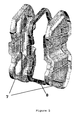
- the intermediate frame or plate insert may be of single-part or multi-part design, and its shape has to adapt to the edge profile of the mold. It will therefore have curvature as required by the mold parting. Even though the parting surface may be complex, the selection of the contact surface for the frame may be such as to maximize the simplicity of the 3D profile ( Figure 5 ). If use is made of divided, multipart intermediate frames or, respectively, plate inserts, the parts are preferably independent of one another, or else movably coupled to one another.
- the multistage process of the invention first closes the mold halves onto the intermediate frame in such a way that between each mold half and the frame there is a parison which has previously undergone division into two parts, but the parisons or semifinished products do not come into direct contact with one another. After molding of the semifinished products in the mold halves in a first step, the mold is opened and the intermediate frame is removed. At this juncture, there is full access to the inside of the subsequent hollow article, and it is therefore now possible to attach even large incorporated parts and position them precisely.
- a further closure movement then provides the final closing of the mold halves together, so that the semifinished products come into direct contact with one another and can then be bonded or welded.
- the term multistage is therefore used for the process described. In the two stages described, the displacement at which the mold is regarded as closed differs by the thickness of the intermediate frame.
- the removal of the intermediate frame from the space between the mold halves may take place by translation or rotation, and a suitable robot may also be used for this purpose.
- Figure 1 shows a displacement/time diagram for the process of the invention.
- the molding cycle for the planar-surface parts begins with an open mold at the juncture to. Once the semifinished products have been placed in the mold halves, these are closed onto the intermediate frame or plate insert, and then during the period T1 the two half shells are shaped by blowing and/or thermoforming from the inside. The mold is then reopened at the end of this first stage of the process. During the period T2 there is now open access to the inside of the two half shells, providing the opportunity to position incorporated parts, for example, or coat the insides of the half shells. The intermediate frame is removed at the same time.
- the mold halves, this time without intermediate frame, are then closed together, whereupon the semifinished products are bonded or welded together.
- a second stage of the process now uses blowing and, where appropriate, thermoforming to provide substantially complete shaping and cooling of the hollow article formed from the welded half shells.
- the mold is then reopened, and during the period T4 the hollow article is removed from the mold and the intermediate frame is reinserted, permitting recommencement of the cycle from the start.
- stage 1 For example, if the time selected for stage 1 (T1) is longer than the second closure time without intermediate frame T3, the result is substantially molding by thermoforming. In the reverse case, if the second closure time T3 is longer, the hollow article is formed substantially by blow molding. Between these, it is possible to set any of the intervening levels for the ratio of the molding methods to one another, i.e. any desired single- or multistage combinations of thermoforming procedures and blow molding procedures.
- stage 1 is approximately that of the entire cycle time
- the process corresponds to the production of thermoformed half shells which are individually removed in order to be subjected to completion subsequently.
- the duration (T1) selected for stage 1 is such that the half shells can retain their shape, for example to allow incorporation of parts in the period T2, but at the same time the plastic is sufficiently hot to be welded during the second closure time T3.
- One way of improving shape retention is to apply a vacuum between the mold and the plastic, for example via suitable holes through the mold extending to the cavity.
- the duration of the first stage of the process (closing with frame) is shortened so greatly that it approaches zero, the process corresponds to the known blow molding process.
- This variability of the process of the invention permits precise individual adaptation of the molding steps to the structural requirements of the molds and of the hollow article to be produced.
- blow molding and thermoforming steps can be selected as appropriate for the rheology of the respective plastics used, so as to allow the semifinished product to fit into the mold halves in an ideal manner and with consistent thickness.
- Another particular advantage is that, in the process of the invention, when the mold is opened to remove the intermediate frame the two half shells are fully accessible, considerably facilitating the incorporation of components in the interior of the container. Because the semifinished products or half shells remain in the mold halves here, appropriate temperature-control of the mold and of the intermediate frame/plate insert can avoid any excessive cooling of the plastic, particularly at the subsequent inside of the hollow article, thus permitting direct welding of incorporated parts to the plastic which retains melt heat and ensuring that the half shells are still sufficiently hot to be welded to one another directly in the subsequent step.
- planar-surface parts by way of a blow molding plant also permits accurate and reproducible wall-thickness control and high design freedom, due to the high flexibility of the molding steps.
- layers made from barrier polymers can be integrated into the semifinished product. If a single-layer semifinished product is manufactured on a blow molding plant, barrier layers can be employed subsequently, for example by fluorination or painting.
- the coating procedures may advantageously take place on the fully accessible half shells after opening of the mold, prior to or after the attachment of incorporated parts.
- the intermediate frame of the invention fulfils a number of functions.
- the main function is to hold or secure the peripheral edge of the semifinished product in the mold half during the molding procedure.
- the frame also serves as a surface which applies pressure during pinch-off of the semifinished product by way of the pinch-off edge of the mold.
- the functions of securing and pinch-off are decisively affected by the geometry and design of the edge regions, both of the intermediate frame and of the mold.
- the manner of sealing-off of the semifinished product is such as to permit at least some degree of blowing of the semifinished product before the first molding stage has ended, without hindering the subsequent formation of a clean pinch-off weld.
- the intermediate frame or plate insert can assume other functions, for example the controlled introduction or dissipation of compressed air via appropriate holes. This permits the function of flushing or ventilation to be exercised. It is also possible for additional functional units, including moveable functional units, such as stamps or jaws, to be arranged on, or integrated on or in, the frame.
- the intermediate frame may also be used as a support for components to be introduced.
- this may have equipment for the cooling or heating of at least one subregion of the frame.
- the temperature control may provide differences as a function of time and/or of location, and certain regions of the frame/plate may therefore, where appropriate, be capable of control to different temperatures during a process cycle.
- An example of a method for temperature control is to pass a suitable cooling medium or heating medium through channels. It is also possible to use electrical cartridge heaters or thermocouples. Particular preference is given to precise temperature control, preferably heating of the pinch-off edge of the mold, in order to achieve greater homogeneity and freedom from stress at the pinch-off edge.
- the edge region of the half shell is locally heated or locally temperature-controlled.
- the temperature control of the plate insert in the region in contact with the pinch-off edge of the mold preferably takes place on both sides of the edge of the plate, or else may be present only on one side.
- the present invention also provides a hollow plastic article which can be produced by the process described above.
- the invention provides preferred use of the hollow plastic articles prepared by the process of the invention as plastic fuel tanks in motor vehicles, or else as a gasoline canister, a plastic tank for storage or transport of heating oil, diesel, or the like, or a transport container on a utility vehicle, for example for crop sprays, or a solvent container, plastic bottle, or the like.
- Another advantage of the production process of the present invention is that, prior to the bonding of the molded semifinished products, it is possible without difficulty where appropriate to attach incorporated parts, such as components of a fuel system, to the inside of the half shells.
- the invention therefore provides for incorporated parts, such as ventilation lines for pressure equilibration within the tank, fuel lines for equilibration of liquids within the tank, valves, anti-surge cups, or pump-related and/or tank sensor modules, for example, to be attached to the inside of the half shells before welding the thermoformed semifinished products.
- the semifinished products may be bonded by adhesive bonding with suitable adhesives or by hot welding, or by a combination of these two. Preference is given to welding.
- the welding of the semifinished products preferably takes place "while still hot", i.e. the edges of the half shells which still retain melt heat after molding in stage 1 and removal of the intermediate frame are brought directly into contact with one another by closing the mold halves in stage 2, and the half shells are directly welded to one another, with flash pinch-off.
- this may be achieved by providing equipment for cooling or heating in the intermediate frame, as described above.
- Another substantial advantage of the process of the invention is that precise control is possible of the wall thickness of the plastic parison on the coextrusion blow molding plant used.
- the precise control of the wall thickness of the parison on the coextrusion blow molding plant gives a significant improvement in wall-thickness control in the subsequent thermoforming process.
- the diameter or circumference of the plastic parison is set by way of the diameter of the parison die, and has to be adapted to the requirements of the subsequent steps of the process.
- the wall thickness of the plastic parison may be controlled in an axial direction during the extrusion process with the aid of the variable die gap. Radial wall thickness control may also be implemented by using profiled die/mandrel pairs or flexible die rings which can be deformed using suitable actuators (partial wall-thickness control).
- the parison is cut open to give at least one, preferably two, or else more, for example three or four, planar-surface parts.
- the cutting of the plastic parison takes place prior to separation from the die, i.e. before the extrusion process is complete, or immediately afterward.
- the plastic parison is extended perpendicularly to the direction of extrusion with the aid of a stretching device prior to cutting. If only one side of the tubular parison is cut open, the result is a large-surface-area semifinished product which can be placed over a thermoforming mold with two chambers for the upper shell and lower shell in such a way that two half shells are produced and are then separated from one another and welded. It is preferable for two sides of the tubular parison to be cut open so that two planar-surface parts are obtained, each of which is molded into a thermoforming mold.
- the invention also provides for the parison to be cut open to give more than two parts and, where appropriate, for the finished part to be manufactured from more than two subshells.
- thermoforming process to give semifinished products of half-shell type.
- Existing coextrusion blow molding plants may also be used advantageously for the process of the invention. It is merely necessary for the blow molding plants to be supplemented by appropriate cutting units, preferably robots, and thermoforming units, and it is in principle also possible here to use the existing clamping units of the blow molding plants for the thermoforming, completion, and welding processes.
- the manner of cutting the plastic parison is therefore as follows:
- the nature of the surface of the cutting device or of the knife or parts thereof may be smooth or else grooved. Depending on the requirement, part or all of the cutting device or of the knife itself may be heated or cooled.
- Suitable coatings encompass polytetrafluoroethylene (PTFE), for example, or other fluorinated hydrocarbons.
- the arrangement of the knife or of the cutting device may be at the mandrel and/or at the die of the extrusion equipment. In some instances it has proved advantageous to cut the parison up immediately on discharge from the die.
- the arrangement of the cutting device or of the knives may be either horizontal or vertical.
- the plastic melt may be separated with the aid of flow dividers arranged in the interior of the blow molding head.
- flow dividers may be used simply as displacers which create a point of weakness in the parison tube with severity sufficient for the parison to break apart spontaneously or with slight assistance.
- the second possibility is a procedure similar to the process for producing a window strip, in which a transparent plastic is fed in by way of the flow dividers.
- the plastic used for the purpose of separating the tube is incompatible with the plastics of the parison. Due to the incompatibility, the "separator strip" thus introduced can be pulled away without any great effort, whereupon the remaining tube sections (curtains) are then used as planar-surface parts in the process of the invention.
- suitable incompatible polymers are polyamides, polystyrene, and, where appropriate, also polypropylene.
- Another way of separating the tube or the parison uses a glowing wire.
- the abovementioned glowing wire may either be fixed or movable. Lasers may also be used to separate the melt or the parison into curtains.
- the abovementioned cutting devices including knives, flow dividers, glowing wire, and lasers, may have a rigid arrangement, or else oscillate. They may also pass over the melt rapidly in order to avoid undesirable displacement of material. As an alternative, the abovementioned cutting devices may be of movable design.
- One particularly preferred draw-off system encompasses one or more roller-type draw-off units per semifinished product, for example driven rollers, especially pneumatically floating driven rollers.
- driven rollers especially pneumatically floating driven rollers.
- the driven units or driven rollers exert tension on the parison or the curtains. This tension acts together with the compression generated by the extrusion process to guide the parison consistently in the desired manner over the cutting device.
- driven rollers or rolls has the additional advantage that the parison section is immediately distanced from the cutting knife after separation of the parison, thus avoiding any adhesion.
- the driven rollers are integrated within the cutting device, preferably a triangular cutting knife.
- the driven rollers may also be attached separately, i.e. outside the cutting device.
- the driven units have a profile or groove or a suitable coating, in order to ensure sufficient friction or, respectively, continuous transporting of the thermoplastic composition.
- the velocity of the parison or parison section relative to that of the driven unit may be from 0 to a positive difference in favor of the velocity of the driven unit.
- a positive difference in favor of the driven unit is preferred.
- the equipment for guiding the parison or the parison sections also comprises guide rollers.
- These guide rollers may, where appropriate, also be driven.
- An example of the use of these guide rollers is to control the distance between the parison sections obtained, or else to deform, and in particular flatten, the parison sections.
- the cutting or guiding devices have guide rollers as well as the abovementioned driven rollers.
- roller-type drive units for example driven rollers, and particularly preferably pneumatic floating rollers.
- the driven units or driven rollers exert tension on the parison or the curtains. This tension acts together with the compression generated by the extrusion process to guide the parison consistently in the desired manner over the cutting device.
- driven rollers or rolls has the additional advantage that the parison section is immediately distanced from the cutting knife after separation of the parison, thus avoiding any adhesion.
- the driven rollers are integrated within the cutting device, preferably a triangular cutting knife.
- the driven rollers may also be attached separately, i.e. outside the cutting device.
- the invention provides for the use of robots for individual operations in the process, in particular for the separation, transport, and cutting of the plastic parison, and also the insertion of incorporated parts into the hollow article.
- the hollow plastic articles produced by the process of the invention preferably have a structure of two or more layers, since the plastic material is subject to high stress levels and requirements are stringent, for example with respect to barrier action.
- the hollow plastic articles of the invention preferably have a structure of at least two layers. These layers always involve a supporting base layer which usually forms the inner surface of the hollow article. This layer is therefore of decisive importance for the leakproof nature of the container and its mechanical stability.
- the plastic parison produced has at least one layer made from polymeric material, preferably selected from the group consisting of polyethylene, polypropylene, polyvinyl chloride, polyamide, polyketone, polyester, and mixtures of these.
- the plastic parison produced preferably has at least one layer made from polyethylene, in particular polyethylene with a density of 0.93 to 0.97 g/cm 3 .
- the plastic parison has a structure composed of two or more layers, preferably encompassing base layer, regrind layer, adhesion-promoter layer, and/or barrier layer.
- the layer thickness distribution within the finished part and therefore the parison depends on the number of layers. Given below is the layer thickness distribution in a plastic parison produced by the process of the invention and having a structure composed of six layers.
- a particularly preferred embodiment produces a plastic parison and, respectively, a hollow plastic article with a structure composed of six layers, encompassing, from the outside to the inside:
- Suitable base materials encompass high-density polyethylene (HDPE) with a density of from 0.940 to 0.960 g/cm 3 , in particular from 0.943 to 0.955 g/cm 3 , and particularly preferably from 0.943 to 0.950 g/cm 3 .
- the melt flow ratio of polyethylene materials suitable for the invention is from 1.5 to 20 g/10 min (MFR (190°C/21.6 kg)), in particular from 2 to 10 g/min, and particularly preferably from 3 to 8 g/10 min.
- MFR 190°C/21.6 kg
- Other abovementioned polymeric materials are, of course, also suitable as supporting base material.
- Suitable barrier materials encompass ethylene-vinyl alcohol copolymer (EVOH), polyamide, and also other barrier polymers, such as polyesters, in particular polybutylene terephthalate, fluoropolymers, such as polyvinylidene fluoride, ethylene-tetrafluoroethylene copolymer (ETFE), tetrafluoroethylene-hexafluoropropylene-vinylidene fluoride copolymer (THV), and also liquid-crystalline polymers (LCPs).
- EVOH ethylene-vinyl alcohol copolymer
- polyamide polyamide
- other barrier polymers such as polyesters, in particular polybutylene terephthalate
- fluoropolymers such as polyvinylidene fluoride, ethylene-tetrafluoroethylene copolymer (ETFE), tetrafluoroethylene-hexafluoropropylene-vinylidene fluoride copolymer (THV), and also liquid-crystalline poly
- nanoparticles are inorganic phyllosilicates whose atomic layers have been parted and thus loosened by intercalated organic molecules.
- the atomic layers can be separated by incorporation into polymeric materials, bringing about extremely fine distribution of the particles.
- the surface of the dispersed particles brings about extreme lengthening of the diffusion path for any permeating molecule, the result being reduced permeation.
- Adhesion promoters suitable for the invention encompass polar-modified polyethylenes (HDPE or LLDPE and LDPE).
- the grafted polyethylenes may also be chemically modified in downstream reactions, for example by introducing amino groups.
- Other materials suitable in principle as adhesion promoters are copolymers of ethylene with vinyl acetate, acrylic acid, or its esters.
- the layer which may be called the regrind layer is preferably produced from what is known as flash, for example that produced during production of the hollow plastic articles and taking the form of residual materials or of production residues.
- the half shells or the hollow plastic article prior to and, respectively, after the welding of the two thermoformed semifinished products are/is given an additional permeation-reducing coating.
- the permeation-reducing coating may be obtained on the plastic containers by direct fluorination, painting, or plasma polymerization, for example.
- a plastic parison is first produced, for example using a 6-layer coextrusion blow molding plant as produced and marketed by the company Krupp Kautex Maschinenbau.
- the coextrusion process gives a tubular parison composed of six layers.
- the layer structure of the parison corresponds to the structure described above (from the outside to the inside: HDPE, regrind, adhesion-promoter, barrier polymer, adhesion-promoter, HDPE).
- the layer thickness distribution of the parison is likewise within the ranges given above.
- the parison wall thickness is adapted to the geometry of the finished part in such a way as to give maximum consistency of wall thickness distribution in the finished part, with no thin areas.
- the parison wall thickness here is controlled by a suitable program which controls the die gap as a function of time (WDS), and, where appropriate, also by radial die gap control (PWDS).
- WDS die gap as a function of time
- PWDS radial die gap control
- the wall thickness distribution depends on the requirements placed upon the mechanical performance of the material, and also in the case of plastic fuel tanks on the required fire performance.
- the diameter or circumference of the parison tube is adapted to the requirements of the mold and can be set without difficulty by way of the selection of the diameter of the die.
- the plastic parison is extruded to the length required for the respective mold.
- the invention provides that the parison can be extruded by way of a suitable stretching device, which in the simplest case is composed of two bars mounted vertically and capable of being moved away from one another hydraulically, for example. If the two bars arranged parallel or else at an angle to one another and located in the interior of the parison tube are moved away from one another, the melt over the entire length of the parison tube experiences extension transversely to the direction of extrusion.
- the stretching device described above may, of course, also be of multipart design, permitting the parison tube to be subjected to various controlled degrees of extension or spreading in an axial direction.
- the use of a stretching device to shape the material provides not only a method of controlled preshaping of the coextruded tube but also a method of controlling the wall thickness of the parison.
- the resultant plastic parison is separated below the die of the extrusion head.
- the molten parison stretched and held in the stretching device is then swung out of the parison extrusion area so that in the next operation it can be cut open along at least two lines matched to the requirements of the subsequent steps of the process and of the finished part.
- holding devices are brought up to both sides of the plastic parison. These are capable of securing and positioning the halves of the parison which are produced in the cutting process. Examples of suitable holding devices are suction heads.
- the separation and transporting of melt tubes is a step known in the prior art and is described in detail in EP 0 653 286 , for example.
- the partitioning of the plastic parison in an axial direction preferably takes place using robots, which permit three-dimensional control of the cutting tools.
- the planar-surface shape of the semifinished product preferably be adapted to the edge curvature of the thermoforming mold, and this makes it possible to minimize the proportion of flash produced.
- the melt tube it is also possible for the melt tube to be cut up in an axial direction before completion of the extrusion process, or else immediately after, prior to separation from the die. If the cutting-up process takes place during the extrusion process, the planar-surface part may itself be stretched perpendicularly to the direction of extrusion.
- the next step then brings the resultant planar-surface parts, which mostly have the shape of sheets, to the two thermoforming mold halves, preferably located opposite one another. Robots may also carry out this function. Where appropriate, the thermoforming mold halves have different shapes, for the upper and, respectively, lower portion of the hollow plastic article to be manufactured.
- the two mold halves are closed onto the intermediate frame, each mold half closing onto one side of the frame. The design of the intermediate frame is such that contact of the two semifinished products is prevented.
- Subatmospheric pressure is applied within the mold halves, and/or compressed air is injected from the center of the closed mold, thus sucking the molten semifinished products into the mold or, respectively, pressing these against the mold by virtue of the compressed air, and use of an appropriate pressure-time profile here can further optimize the multiaxial extension of the melt and thus also the wall thickness distribution in the half shells to be manufactured. It is also possible for the thermoforming steps and blow molding steps to be carried out in succession or simultaneously in any desired sequence and combination.
- the mold After molding of the semifinished products into the mold halves, the mold is opened and the intermediate frame removed. Where appropriate, incorporated parts are then assembled into the half shells, and/or the insides of the half shells are coated.
- incorporated parts are then assembled into the half shells, and/or the insides of the half shells are coated.
- ventilation lines for pressure equilibration within the tank fuel lines for equilibration of liquids within the tank, valves, anti-surge cups, or pump-related and/or tank sensor modules for refuelling into the tank half shells, and to weld these to the inner surface, which retains the melt heat.
- the two half shells still located in the molds are brought together and are bonded to one another by pressing the two molds together, by again closing the mold, this time with no intermediate frame.
- those portions of the two semifinished products which lie on the face sides of the mold halves are brought into contact with one another and preferably welded.
- the design of the molds and of their closing movements are such that when the half shells are pressed together material can flow into suitable chambers during the welding procedure, so that the geometry of the weld can be adapted to the requirements placed upon component strength and resistance to fuel permeation.
- FIG. 2A is a diagram of the device of the invention for partitioning a plastic parison.
- the plastic parison is in the form of a tube when discharged from the die of the extrusion equipment (1).
- the equipment also encompasses a heatable holder (4) on which the cutting device has been attached.
- Two pneumatically driven rolls (2) arranged in the immediate vicinity of the cutting device function as an inventive means of drive.
- Installation in the immediate vicinity of the body (3) has the advantage that the two resultant parison sections (6) are distanced from the cutting device immediately after separation of the parison, thus avoiding any adhesion of the semifinished sheets to the device.
- the tension exerted by the driven rolls (2) guides the plastic parison consistently over the cutting device, so that the resultant semifinished sheets have no, or comparatively very low levels of, creasing or irregularity, in particular at the margins, i.e. at the cut edges.
- Figure 2B is a diagram of another device of the invention for partitioning a plastic parison.
- the device shown in Figure 2 differs from the device of Figure 1 merely by way of two guide rollers (5) additionally installed. These guide rollers eliminate undesired contact between the semifinished products (6) after the separation procedure, and also give the desired free space for components and devices to be introduced.
- the guide rollers (5) may be moved transversely to the direction of extrusion. The movability of the guide rollers transversely to the direction of extrusion permits controlled setting of the distance between the semifinished products obtained.
- the driven rolls (2) in the device of Figure 2 have been set into or integrated into the cutting device (3).
- Figure 3 depicts the distortion of the parison when using devices not according to the invention (without means of drive). This gives considerable deformation of the resultant cut edges and also of the semifinished products themselves.
- Figure 4 depicts the device of the invention and the resultant partitioned parisons or resultant semifinished sheets. These have no creasing or irregularity, in particular at the margins, i.e. at the cut edges.
- the polymer processed was the same as in Figure 3 .
- Figure 5 illustrates a intermediate frame (8) between two half shells (7).
Landscapes
- Engineering & Computer Science (AREA)
- Mechanical Engineering (AREA)
- Manufacturing & Machinery (AREA)
- Physics & Mathematics (AREA)
- Thermal Sciences (AREA)
- Life Sciences & Earth Sciences (AREA)
- Forests & Forestry (AREA)
- Geometry (AREA)
- Blow-Moulding Or Thermoforming Of Plastics Or The Like (AREA)
- Cooling, Air Intake And Gas Exhaust, And Fuel Tank Arrangements In Propulsion Units (AREA)
Claims (17)
- Verfahren zur Herstellung von Kunststoffhohlkörpern, das die folgenden Schritte umfasst:a) Herstellen eines schlauchförmigen Kunststoffvorformlings mittels Extrusion oder Koextrusion;b) Aufschneiden des Kunststoffvorformlings zur Herstellung von zwei planaren Oberflächenteilen mit pneumatisch angetriebenen Walzen (2), die in der unmittelbaren Umgebung der Schneidevorrichtung (3) zum Abstand der beiden sich ergebenden Vorformlingsteile (6) von der Schneidevorrichtung (3) unmittelbar nach der Trennung des Vorformlings angeordnet sind;c) Formen der planaren Oberflächenteile in zwei Formhälften zum Erhalt von Halbschalen (7), wobei ein herausnehmbarer Zwischenrahmen (8) die Formhälften mindestens entlang den peripheren Kanten dergestalt voneinander trennt, dass die Halbzeuge/Halbschalen (7) nicht in Kontakt miteinander kommen;d) Öffnen der Formhälften und Herausnehmen des Zwischenrahmens (8);e) Schließen der Formhälften, mit dem Ergebnis, dass die Halbschalen (7) entlang dem peripheren Rand in Kontakt miteinander kommen; undf) Verbinden der Halbschalen (7) zum Erhalt eines Hohlkörpers.
- Verfahren nach Anspruch 1, worin die Einbauteile, nach Herausnahme des Zwischenrahmens (8), auf der Innenseite von mindestens einer der geformten Halbschalen (7) befestigt werden können.
- Verfahren nach Anspruch 2, worin die Einbauteile zum Beispiel Lüftungsleitungen für den Druckausgleich im Tank, Kraftstoffleitungen für den Flüssigkeitsausgleich im Tank, Ventile, Schwalltöpfe oder Pumpen- und/oder Tank-Sensormodule sind.
- Verfahren nach einem der vorangehenden Ansprüche, worin die planaren Oberflächenteile zum Erhalt von Halbschalen (7) in den Formhälften mittels Thermoformen und/oder Blasformen geformt werden.
- Verfahren nach einem der vorangehenden Ansprüche, worin das Verbinden der Halbschalen (7) durch Klebebondieren und/oder Schweißen erfolgt.
- Verfahren nach Anspruch 5, worin die Wärme vom Thermoformen zum Verschweißen der Halbschalen eingesetzt wird.
- Verfahren nach einem der vorangehenden Ansprüche, worin nach dem Verbinden der Halbschalen (7) weiteres Formen der Hohlkörper mittels Thermoformen und/oder Blasformen erfolgt.
- Verfahren nach einem der vorangehenden Ansprüche, worin der verwendete Zwischenrahmen (8) einen Platteneinsatz umfasst, der im Wesentlichen das vollständige Ausfüllen des Bereichs zwischen den beiden Formhälften vorsieht.
- Verfahren nach einem der vorangehenden Ansprüche, worin der Zwischenrahmen (8) Vorrichtungen zum Kühlen oder Erwärmen besitzt.
- Verfahren nach einem der vorangehenden Ansprüche, worin der Zwischenrahmen (8) Vorrichtungen zum kontrollierten Erwärmen der Kanten der geformten Halbschalen (7) besitzt.
- Verfahren nach einem der vorangehenden Ansprüche, worin der Zwischenrahmen (8) Vorrichtungen zum Erwärmen der Quetschkante von mindestens einer Formhälfte, bevorzugt von beiden, besitzt.
- Verfahren nach einem der vorangehenden Ansprüche, worin der Zwischenrahmen (8) oder der Platteneinsatz eine einteilige oder mehrteilige Konstruktion ist.
- Verfahren nach einem der vorangehenden Ansprüche, das ohne zusätzliche Erwärmungs- oder Kühlungsschritte abläuft.
- Verfahren nach einem der vorangehenden Ansprüche, worin der Kunststoffvorformling aus mindestens einer Schicht aus polymerem Material hergestellt ist, die bevorzugt aus der Gruppe ausgewählt ist, die aus Polyethylen, Polypropylen, Polyvinylchlorid, Polyamid, Polyketon, Polyester und Gemischen derselben besteht.
- Verfahren nach einem der vorangehenden Ansprüche, worin der Kunststoffvorformling eine Struktur aufweist, die sich aus zwei oder mehr Schichten zusammensetzt, die bevorzugt eine Basisschicht, Mahlgutschicht, Haftvermittlungsschicht und/oder Barriereschicht umfassen.
- Verfahren nach einem der vorangehenden Ansprüche, worin der Kunststoffvorformling eine Struktur aufweist, die aus zwei oder mehr Schichten besteht, umfassend von außen nach innen:• eine HDPE-Schicht mit einer Dicke von 5 bis 30 %,• eine Mahlgutschicht mit einer Dicke von 10 bis 82 %,• eine Haftvermittlungsschicht mit einer Dicke von 1 bis 5 %,• eine Barriereschicht mit einer Dicke von 1 bis 10 %,• eine Haftvermittlungsschicht mit einer Dicke von 1 bis 5 %,• eine HDPE-Schicht mit einer Dicke von 10 bis 40 %,
jeweils bezogen auf die Gesamtdicke der Behälterwand. - Verwendung des Verfahrens nach einem der Ansprüche 1 bis 16 zum Erhalt eines Kunststoffhohlkörpers, der als Kraftstoffbehälter aus Kunststoff in Kraftfahrzeugen, als Benzinkanister, Kunststofftank zur Lagerung oder zum Transport von Heizöl oder Diesel, oder Transportbehälter auf einem Nutzfahrzeug, zum Beispiel für Nutzpflanzenspritzmittel, oder Lösungsmittelbehälter oder Kunststoffflasche nützlich ist.
Priority Applications (1)
| Application Number | Priority Date | Filing Date | Title |
|---|---|---|---|
| EP10008406.0A EP2253457B1 (de) | 2002-07-12 | 2003-07-09 | Mehrstufenverfahren zur Herstellung hohler Kunststoffartikel aus Halbschalen |
Applications Claiming Priority (5)
| Application Number | Priority Date | Filing Date | Title |
|---|---|---|---|
| DE10231866A DE10231866A1 (de) | 2002-07-12 | 2002-07-12 | Mehrstufiges Verfahren zur Herstellung von Kunststoffhohlkörpern aus Halbschalen |
| DE10231866 | 2002-07-12 | ||
| US41699002P | 2002-10-08 | 2002-10-08 | |
| US416990P | 2002-10-08 | ||
| PCT/EP2003/007353 WO2004007182A1 (en) | 2002-07-12 | 2003-07-09 | Multistage process for producing hollow plastic articles from half shells |
Related Child Applications (2)
| Application Number | Title | Priority Date | Filing Date |
|---|---|---|---|
| EP10008406.0A Division EP2253457B1 (de) | 2002-07-12 | 2003-07-09 | Mehrstufenverfahren zur Herstellung hohler Kunststoffartikel aus Halbschalen |
| EP10008406.0 Division-Into | 2010-08-12 |
Publications (2)
| Publication Number | Publication Date |
|---|---|
| EP1534496A1 EP1534496A1 (de) | 2005-06-01 |
| EP1534496B1 true EP1534496B1 (de) | 2010-10-27 |
Family
ID=30116637
Family Applications (1)
| Application Number | Title | Priority Date | Filing Date |
|---|---|---|---|
| EP20030763751 Expired - Lifetime EP1534496B1 (de) | 2002-07-12 | 2003-07-09 | MEHRSTUFENPROZESS ZUR HERSTELLUNG VON HOHLEN KUNSTSTOFFGEGENSTûNDEN AUS HALBSCHALEN |
Country Status (7)
| Country | Link |
|---|---|
| US (2) | US20060141184A1 (de) |
| EP (1) | EP1534496B1 (de) |
| JP (1) | JP2005532204A (de) |
| KR (1) | KR20090128510A (de) |
| CN (1) | CN100548640C (de) |
| AU (1) | AU2003250916A1 (de) |
| WO (1) | WO2004007182A1 (de) |
Cited By (1)
| Publication number | Priority date | Publication date | Assignee | Title |
|---|---|---|---|---|
| CN110248796A (zh) * | 2017-02-17 | 2019-09-17 | 株式会社日本制钢所 | 坯料分离装置,中空成型机及中空成型制品制造方法 |
Families Citing this family (40)
| Publication number | Priority date | Publication date | Assignee | Title |
|---|---|---|---|---|
| DE10231867A1 (de) | 2002-07-12 | 2004-01-22 | Basell Polyolefine Gmbh | Führung eines aufgeschnittenen Vorformlings |
| US7789987B2 (en) * | 2004-06-03 | 2010-09-07 | Mitsui Chemicals, Inc | Method of manufacturing resin hollow body using a blow molding die assembly |
| FR2873321B1 (fr) | 2004-07-23 | 2008-05-09 | Inergy Automotive Systems Res | Procede pour la fixation d'un accessoire dans un reservoir a carburant en matiere plastique |
| FR2877256B1 (fr) * | 2004-10-28 | 2008-10-03 | Inergy Automotive Systems Res | Procede pour la fabrication d'un reservoir a carburant en matiere plastique comprenant une goulotte integree |
| FR2879122B1 (fr) * | 2004-12-15 | 2008-10-03 | Inergy Automotive Systems Res | Procede pour la fabrication d'un reservoir a carburant en matiere plastique ayant une resistance au fluage amelioree |
| FR2879494B1 (fr) * | 2004-12-16 | 2007-03-09 | Inergy Automotive Systems Res | Procede pour la fabrication d'un corps creux multicouche comprenant au moins une soudure |
| FR2882962B1 (fr) † | 2005-03-11 | 2009-07-10 | Inergy Automotive Systems Res | Procede pour la fabrication d'un reservoir a carburant en matiere plastique |
| CN101208188A (zh) * | 2005-06-28 | 2008-06-25 | 因勒纪汽车系统研究公司 | 用于生产设置有内部附件的燃料箱的方法 |
| JP2008546574A (ja) | 2005-06-28 | 2008-12-25 | イナジー・オートモーティブ・システムズ・リサーチ・(ソシエテ・アノニム) | 内部付属品を備える燃料タンクの製造方法 |
| JP5378802B2 (ja) * | 2006-02-03 | 2013-12-25 | イナジー・オートモーティブ・システムズ・リサーチ・(ソシエテ・アノニム) | 内部付属品を備えた燃料タンクを製造するための方法および装置 |
| FR2901190B1 (fr) * | 2006-05-16 | 2009-01-23 | Inergy Automotive Systems Res | Reservoir liquide et procede pour le fabriquer |
| DE102006027254B4 (de) | 2006-06-09 | 2009-01-15 | Kautex Textron Gmbh & Co. Kg | Verfahren zur Herstellung von Hohlkörpern aus thermoplastischem Kunststoff durch Extrusionsblasformen |
| US7922949B2 (en) * | 2006-07-07 | 2011-04-12 | Kautex Textron Gmbh & Co. Kg | Procedure for producing hollow bodies of thermoplastic material |
| DE102006042065B4 (de) | 2006-09-05 | 2021-05-12 | Kautex Textron Gmbh & Co. Kg | Verfahren und Vorrichtung zur Herstellung von bandförmigen Kunststoffvorformlingen |
| JP5006400B2 (ja) * | 2006-10-05 | 2012-08-22 | イナジー・オートモーティブ・システムズ・リサーチ・(ソシエテ・アノニム) | パリソンからプラスチック中空体を製造するための方法およびパリソン押出し用ダイ |
| DE102007037422A1 (de) * | 2007-08-08 | 2009-02-19 | Perma-Tec Gmbh & Co. Kg | Schmierstoffspender |
| US7976754B2 (en) * | 2007-08-29 | 2011-07-12 | Inergy Automotive Systems Research (S.A.) | Process for manufacturing a plastic hollow body, device and equipment for the implementation thereof |
| DE102007059839A1 (de) * | 2007-12-11 | 2009-06-25 | Harald Dipl.-Ing. Feuerherm | Schlauchförmiger Vorformling und Herstellung blasgeformter Teile und Verfahren sowie Vorrichtung zur Herstellung des Vorformlings |
| DE102008027823B3 (de) * | 2008-06-11 | 2010-02-11 | Kautex Textron Gmbh & Co. Kg | Verfahren zur Herstellung eines Kraftstoffbehälters für Kfz sowie Kraftstoffbehälter für Kfz |
| DE102008027824A1 (de) * | 2008-06-11 | 2009-12-17 | Kautex Textron Gmbh & Co. Kg | Verfahren zur Herstellung von Hohlkörpern aus thermoplastischem Kunststoff sowie Vorrichtung zur Herstellung von Hohlkörpern aus thermoplastischem Kunststoff |
| CN102066086B (zh) * | 2008-06-23 | 2014-06-04 | 因勒纪汽车系统研究公司 | 用于制造燃料储箱的方法 |
| DE102008030318A1 (de) * | 2008-06-30 | 2009-12-31 | Ti Automotive Technology Center Gmbh | Verfahren zur Herstellung eines Kunststoffbehälters |
| EP2141000B1 (de) * | 2008-06-30 | 2014-02-26 | TI Automotive Technology Center GmbH | Verfahren und Vorrichtung zur Herstellung eines Artikels |
| CN102639308B (zh) * | 2009-12-09 | 2016-08-17 | 赫斯基注塑系统有限公司 | 包括一体化加工至歧管主体的熔体流动控制结构的热流道系统 |
| US8721956B2 (en) | 2010-03-03 | 2014-05-13 | Ti Automotive Technology Center Gmbh | Method of forming a fluid receptacle |
| FR2957018B1 (fr) * | 2010-03-08 | 2012-10-12 | Inergy Automotive Systems Res | Procede et appareillage pour la fabrication d'un corps creux en matiere plastique a partir de deux feuilles |
| DE102010025006A1 (de) * | 2010-06-24 | 2011-12-29 | Kautex Textron Gmbh & Co. Kg | Verfahren zur Herstellung von Hohlkörpern aus thermoplastischem Kunststoff sowie Vorrichtung zur Durchführung des Verfahrens |
| DE102010027096A1 (de) * | 2010-07-13 | 2012-01-19 | Kautex Textron Gmbh & Co. Kg | Kraftstoffbehälter aus Kunststoff und Verfahren zu dessen Herstellung |
| WO2012075355A1 (en) | 2010-12-03 | 2012-06-07 | Salflex Polymers Limited | Deployable fuel tank baffle and fuel tank system |
| CN102173047B (zh) * | 2010-12-09 | 2013-04-17 | 亚普汽车部件股份有限公司 | 一种两片型坯成型方法及其成型组合装置 |
| EP2484509A1 (de) * | 2011-02-02 | 2012-08-08 | Inergy Automotive Systems Research (Société Anonyme) | Verfahren zur Herstellung eines Kraftstofftanks |
| JP5554743B2 (ja) * | 2011-04-05 | 2014-07-23 | 株式会社日本製鋼所 | 中空成形方法及び装置 |
| DE102012001928A1 (de) | 2012-02-02 | 2013-08-08 | Kautex Maschinenbau Gmbh | Verfahren zur Herstellung eines Kunststoffartikels sowie Teil des Blasformwerkzeuges |
| DE102013203085A1 (de) | 2013-02-25 | 2014-08-28 | Ti Automotive Technology Center Gmbh | Blasformverfahren |
| JP2015101000A (ja) * | 2013-11-25 | 2015-06-04 | トヨタ自動車株式会社 | 樹脂シートの製造装置、樹脂シートの製造方法及び燃料タンクの製造方法 |
| CN104986033B (zh) * | 2015-07-13 | 2018-05-01 | 亚普汽车部件股份有限公司 | 油箱成型刚性组件及油箱成型方法 |
| WO2017210784A1 (en) * | 2016-06-06 | 2017-12-14 | Nureva Inc. | Time-correlated touch and speech command input |
| DE102017217468B4 (de) | 2017-09-29 | 2021-01-14 | Kautex Textron Gmbh & Co. Kg | Verfahren zur herstellung von kunststoffhohlkörpern |
| CN108372670A (zh) * | 2018-02-09 | 2018-08-07 | 佛山市顺德区瑞良塑料制品有限公司 | 一种塑料瓶子的生产方法及生产装置 |
| CN111136895B (zh) * | 2019-12-31 | 2021-12-24 | 佛山市顺德区耀森智能科技有限公司 | 一种涂抹涂料用防溅涂料桶材料的制备方法 |
Family Cites Families (25)
| Publication number | Priority date | Publication date | Assignee | Title |
|---|---|---|---|---|
| NL264467A (de) * | 1960-05-06 | 1900-01-01 | ||
| US3849286A (en) * | 1962-12-13 | 1974-11-19 | American Can Co | Treatment of thermoplastic tubing |
| GB1305619A (de) * | 1970-12-16 | 1973-02-07 | ||
| CA993165A (en) * | 1971-11-22 | 1976-07-20 | Peter T. Schurman | Plastic article and blow molding method and apparatus |
| US4028034A (en) * | 1973-01-24 | 1977-06-07 | Cosden Oil & Chemical Company | Method and apparatus for blow molding plastic |
| US4022559A (en) * | 1975-10-06 | 1977-05-10 | Flexible Plastics Corporation | Parison slicer for plastic molding machines |
| US4170449A (en) * | 1978-01-12 | 1979-10-09 | Shuman Jack N | Clamping frame for plastic forming apparatus |
| FR2420415A1 (fr) * | 1978-03-22 | 1979-10-19 | Frame Sa | Procede de fabrication par extrusion de pieces en matiere thermoplastique |
| US4550008A (en) * | 1981-06-15 | 1985-10-29 | Excell Corporation | Method for molding plastic products |
| JPS61261021A (ja) | 1985-05-15 | 1986-11-19 | Kyoraku Co Ltd | 中空成形方法 |
| DE3721459A1 (de) * | 1987-06-30 | 1989-01-12 | Focke & Co | Verfahren und vorrichtung zum zufuehren von verpackungs-zuschnitten zu einem faltaggregat |
| GB9125297D0 (en) * | 1991-11-28 | 1992-01-29 | Kodak Ltd | Photographic processing apparatus |
| JPH06218792A (ja) | 1993-01-21 | 1994-08-09 | Japan Steel Works Ltd:The | プラスチックシートの製造方法及び装置 |
| GB9323267D0 (en) | 1993-11-11 | 1994-01-05 | Hans Schochert | Transportation device for melted plastics |
| DE19814314B4 (de) | 1998-03-31 | 2016-07-28 | Volkswagen Ag | Verfahren zur Herstellung von Hohlkörpern aus thermoplastischem Kunststoff sowie nach diesem Verfahren hergestellter Hohlkörper |
| US6294114B1 (en) * | 1998-08-20 | 2001-09-25 | Scott A. W. Muirhead | Triple sheet thermoforming apparatus, methods and articles |
| US6749418B2 (en) * | 1998-08-20 | 2004-06-15 | Scott A. W. Muirhead | Triple sheet thermoforming apparatus |
| JP4270624B2 (ja) | 1999-01-29 | 2009-06-03 | キョーラク株式会社 | 樹脂中空成形品のブロー成形方法 |
| BE1013191A3 (fr) * | 1999-12-22 | 2001-10-02 | Solvay | Procede de fabrication de corps creux en matiere plastique. |
| US6661339B2 (en) * | 2000-01-24 | 2003-12-09 | Nextreme, L.L.C. | High performance fuel tank |
| DE10010900A1 (de) | 2000-03-07 | 2001-09-13 | Ludwig Kreth | Kombiniertes Extrusions-Press-Verfahren zur Herstellung von Kunststoffteilen aller Art |
| DE10042121A1 (de) * | 2000-08-28 | 2002-03-14 | Basell Polyolefine Gmbh | Verfahren zur Herstellung von Kunststoffhohlkörpern |
| US20020105115A1 (en) * | 2001-02-08 | 2002-08-08 | Changize Sadr | Multiple part molding process |
| US20030090024A1 (en) * | 2001-11-14 | 2003-05-15 | Rubbermaid Incorporated | Method and apparatus for separating molded articles |
| DE10231867A1 (de) | 2002-07-12 | 2004-01-22 | Basell Polyolefine Gmbh | Führung eines aufgeschnittenen Vorformlings |
-
2003
- 2003-07-09 US US10/520,536 patent/US20060141184A1/en not_active Abandoned
- 2003-07-09 EP EP20030763751 patent/EP1534496B1/de not_active Expired - Lifetime
- 2003-07-09 AU AU2003250916A patent/AU2003250916A1/en not_active Abandoned
- 2003-07-09 CN CNB038166224A patent/CN100548640C/zh not_active Expired - Lifetime
- 2003-07-09 KR KR1020097022247A patent/KR20090128510A/ko not_active Withdrawn
- 2003-07-09 JP JP2005505060A patent/JP2005532204A/ja active Pending
- 2003-07-09 WO PCT/EP2003/007353 patent/WO2004007182A1/en not_active Ceased
-
2012
- 2012-09-28 US US13/631,610 patent/US8617344B2/en not_active Expired - Fee Related
Cited By (4)
| Publication number | Priority date | Publication date | Assignee | Title |
|---|---|---|---|---|
| CN110248796A (zh) * | 2017-02-17 | 2019-09-17 | 株式会社日本制钢所 | 坯料分离装置,中空成型机及中空成型制品制造方法 |
| EP3584061A4 (de) * | 2017-02-17 | 2020-12-09 | The Japan Steel Works, Ltd. | Trennvorrichtung für vorformling, hohlformmaschine und verfahren zur herstellung von hohlformkörpern |
| CN110248796B (zh) * | 2017-02-17 | 2021-08-27 | 株式会社日本制钢所 | 坯料分离装置,中空成型机及中空成型制品制造方法 |
| US11179866B2 (en) | 2017-02-17 | 2021-11-23 | The Japan Steel Works, Ltd. | Parison separation device, blow molding machine, and method for manufacturing blow-molded article |
Also Published As
| Publication number | Publication date |
|---|---|
| WO2004007182A1 (en) | 2004-01-22 |
| CN100548640C (zh) | 2009-10-14 |
| US20130025778A1 (en) | 2013-01-31 |
| US20060141184A1 (en) | 2006-06-29 |
| CN1668452A (zh) | 2005-09-14 |
| AU2003250916A1 (en) | 2004-02-02 |
| EP1534496A1 (de) | 2005-06-01 |
| KR20090128510A (ko) | 2009-12-15 |
| US8617344B2 (en) | 2013-12-31 |
| JP2005532204A (ja) | 2005-10-27 |
Similar Documents
| Publication | Publication Date | Title |
|---|---|---|
| US8617344B2 (en) | Multistage process for producing hollow plastic articles from half shells | |
| EP2253457B1 (de) | Mehrstufenverfahren zur Herstellung hohler Kunststoffartikel aus Halbschalen | |
| US6893603B2 (en) | Production of hollow plastic articles | |
| US6866812B2 (en) | Process for manufacturing hollow plastic bodies | |
| CN102802914B (zh) | 容器制造 | |
| CA2663350C (en) | Process for manufacturing a plastic hollow body from a parison and die for extruding a parison | |
| EP2544873B1 (de) | Verfahren und ausrüstung zur herstellung eines kunststoffhohlkörpers aus zwei folien | |
| JP2002254501A (ja) | プラスチック中空体の製造法 | |
| EP2864105B1 (de) | Verfahren und vorrichtung zum thermoformen | |
| US8500437B2 (en) | Process for manufacturing a plastic hollow body, device and equipment for the implementation thereof | |
| WO2009007384A1 (en) | Process and equipment for manufacturing a plastic hollow body from two sheets |
Legal Events
| Date | Code | Title | Description |
|---|---|---|---|
| PUAI | Public reference made under article 153(3) epc to a published international application that has entered the european phase |
Free format text: ORIGINAL CODE: 0009012 |
|
| 17P | Request for examination filed |
Effective date: 20041218 |
|
| AK | Designated contracting states |
Kind code of ref document: A1 Designated state(s): AT BE BG CH CY CZ DE DK EE ES FI FR GB GR HU IE IT LI LU MC NL PT RO SE SI SK TR |
|
| AX | Request for extension of the european patent |
Extension state: AL LT LV MK |
|
| RAP1 | Party data changed (applicant data changed or rights of an application transferred) |
Owner name: BASELL POLYOLEFINE GMBH |
|
| DAX | Request for extension of the european patent (deleted) | ||
| 17Q | First examination report despatched |
Effective date: 20070905 |
|
| GRAP | Despatch of communication of intention to grant a patent |
Free format text: ORIGINAL CODE: EPIDOSNIGR1 |
|
| GRAS | Grant fee paid |
Free format text: ORIGINAL CODE: EPIDOSNIGR3 |
|
| GRAA | (expected) grant |
Free format text: ORIGINAL CODE: 0009210 |
|
| REG | Reference to a national code |
Ref country code: DE Ref legal event code: R081 Ref document number: 60334698 Country of ref document: DE Owner name: BASELL POLYOLEFINE GMBH, DE Free format text: FORMER OWNER: BASELL POLYOLEFINE GMBH, 65926 FRANKFURT, DE |
|
| AK | Designated contracting states |
Kind code of ref document: B1 Designated state(s): AT BE BG CH CY CZ DE DK EE ES FI FR GB GR HU IE IT LI LU MC NL PT RO SE SI SK TR |
|
| REG | Reference to a national code |
Ref country code: GB Ref legal event code: FG4D |
|
| REG | Reference to a national code |
Ref country code: CH Ref legal event code: EP |
|
| REG | Reference to a national code |
Ref country code: IE Ref legal event code: FG4D |
|
| REF | Corresponds to: |
Ref document number: 60334698 Country of ref document: DE Date of ref document: 20101209 Kind code of ref document: P |
|
| REG | Reference to a national code |
Ref country code: DE Ref legal event code: R096 Ref document number: 60334698 Country of ref document: DE Effective date: 20101209 |
|
| REG | Reference to a national code |
Ref country code: NL Ref legal event code: VDEP Effective date: 20101027 |
|
| PG25 | Lapsed in a contracting state [announced via postgrant information from national office to epo] |
Ref country code: AT Free format text: LAPSE BECAUSE OF FAILURE TO SUBMIT A TRANSLATION OF THE DESCRIPTION OR TO PAY THE FEE WITHIN THE PRESCRIBED TIME-LIMIT Effective date: 20101027 Ref country code: PT Free format text: LAPSE BECAUSE OF FAILURE TO SUBMIT A TRANSLATION OF THE DESCRIPTION OR TO PAY THE FEE WITHIN THE PRESCRIBED TIME-LIMIT Effective date: 20110228 Ref country code: BG Free format text: LAPSE BECAUSE OF FAILURE TO SUBMIT A TRANSLATION OF THE DESCRIPTION OR TO PAY THE FEE WITHIN THE PRESCRIBED TIME-LIMIT Effective date: 20110127 Ref country code: FI Free format text: LAPSE BECAUSE OF FAILURE TO SUBMIT A TRANSLATION OF THE DESCRIPTION OR TO PAY THE FEE WITHIN THE PRESCRIBED TIME-LIMIT Effective date: 20101027 Ref country code: SE Free format text: LAPSE BECAUSE OF FAILURE TO SUBMIT A TRANSLATION OF THE DESCRIPTION OR TO PAY THE FEE WITHIN THE PRESCRIBED TIME-LIMIT Effective date: 20101027 Ref country code: SI Free format text: LAPSE BECAUSE OF FAILURE TO SUBMIT A TRANSLATION OF THE DESCRIPTION OR TO PAY THE FEE WITHIN THE PRESCRIBED TIME-LIMIT Effective date: 20101027 Ref country code: NL Free format text: LAPSE BECAUSE OF FAILURE TO SUBMIT A TRANSLATION OF THE DESCRIPTION OR TO PAY THE FEE WITHIN THE PRESCRIBED TIME-LIMIT Effective date: 20101027 |
|
| PG25 | Lapsed in a contracting state [announced via postgrant information from national office to epo] |
Ref country code: GR Free format text: LAPSE BECAUSE OF FAILURE TO SUBMIT A TRANSLATION OF THE DESCRIPTION OR TO PAY THE FEE WITHIN THE PRESCRIBED TIME-LIMIT Effective date: 20110128 |
|
| PG25 | Lapsed in a contracting state [announced via postgrant information from national office to epo] |
Ref country code: EE Free format text: LAPSE BECAUSE OF FAILURE TO SUBMIT A TRANSLATION OF THE DESCRIPTION OR TO PAY THE FEE WITHIN THE PRESCRIBED TIME-LIMIT Effective date: 20101027 Ref country code: CZ Free format text: LAPSE BECAUSE OF FAILURE TO SUBMIT A TRANSLATION OF THE DESCRIPTION OR TO PAY THE FEE WITHIN THE PRESCRIBED TIME-LIMIT Effective date: 20101027 Ref country code: ES Free format text: LAPSE BECAUSE OF FAILURE TO SUBMIT A TRANSLATION OF THE DESCRIPTION OR TO PAY THE FEE WITHIN THE PRESCRIBED TIME-LIMIT Effective date: 20110207 |
|
| PG25 | Lapsed in a contracting state [announced via postgrant information from national office to epo] |
Ref country code: DK Free format text: LAPSE BECAUSE OF FAILURE TO SUBMIT A TRANSLATION OF THE DESCRIPTION OR TO PAY THE FEE WITHIN THE PRESCRIBED TIME-LIMIT Effective date: 20101027 Ref country code: RO Free format text: LAPSE BECAUSE OF FAILURE TO SUBMIT A TRANSLATION OF THE DESCRIPTION OR TO PAY THE FEE WITHIN THE PRESCRIBED TIME-LIMIT Effective date: 20101027 Ref country code: SK Free format text: LAPSE BECAUSE OF FAILURE TO SUBMIT A TRANSLATION OF THE DESCRIPTION OR TO PAY THE FEE WITHIN THE PRESCRIBED TIME-LIMIT Effective date: 20101027 |
|
| PLBE | No opposition filed within time limit |
Free format text: ORIGINAL CODE: 0009261 |
|
| STAA | Information on the status of an ep patent application or granted ep patent |
Free format text: STATUS: NO OPPOSITION FILED WITHIN TIME LIMIT |
|
| 26N | No opposition filed |
Effective date: 20110728 |
|
| REG | Reference to a national code |
Ref country code: DE Ref legal event code: R097 Ref document number: 60334698 Country of ref document: DE Effective date: 20110728 |
|
| PG25 | Lapsed in a contracting state [announced via postgrant information from national office to epo] |
Ref country code: IT Free format text: LAPSE BECAUSE OF FAILURE TO SUBMIT A TRANSLATION OF THE DESCRIPTION OR TO PAY THE FEE WITHIN THE PRESCRIBED TIME-LIMIT Effective date: 20101027 |
|
| PG25 | Lapsed in a contracting state [announced via postgrant information from national office to epo] |
Ref country code: MC Free format text: LAPSE BECAUSE OF NON-PAYMENT OF DUE FEES Effective date: 20110731 |
|
| REG | Reference to a national code |
Ref country code: CH Ref legal event code: PL |
|
| GBPC | Gb: european patent ceased through non-payment of renewal fee |
Effective date: 20110709 |
|
| REG | Reference to a national code |
Ref country code: IE Ref legal event code: MM4A |
|
| PG25 | Lapsed in a contracting state [announced via postgrant information from national office to epo] |
Ref country code: CH Free format text: LAPSE BECAUSE OF NON-PAYMENT OF DUE FEES Effective date: 20110731 Ref country code: LI Free format text: LAPSE BECAUSE OF NON-PAYMENT OF DUE FEES Effective date: 20110731 |
|
| PG25 | Lapsed in a contracting state [announced via postgrant information from national office to epo] |
Ref country code: GB Free format text: LAPSE BECAUSE OF NON-PAYMENT OF DUE FEES Effective date: 20110709 |
|
| PG25 | Lapsed in a contracting state [announced via postgrant information from national office to epo] |
Ref country code: IE Free format text: LAPSE BECAUSE OF NON-PAYMENT OF DUE FEES Effective date: 20110709 |
|
| PG25 | Lapsed in a contracting state [announced via postgrant information from national office to epo] |
Ref country code: CY Free format text: LAPSE BECAUSE OF EXPIRATION OF PROTECTION Effective date: 20101027 Ref country code: LU Free format text: LAPSE BECAUSE OF NON-PAYMENT OF DUE FEES Effective date: 20110709 |
|
| PG25 | Lapsed in a contracting state [announced via postgrant information from national office to epo] |
Ref country code: TR Free format text: LAPSE BECAUSE OF FAILURE TO SUBMIT A TRANSLATION OF THE DESCRIPTION OR TO PAY THE FEE WITHIN THE PRESCRIBED TIME-LIMIT Effective date: 20101027 |
|
| PG25 | Lapsed in a contracting state [announced via postgrant information from national office to epo] |
Ref country code: HU Free format text: LAPSE BECAUSE OF FAILURE TO SUBMIT A TRANSLATION OF THE DESCRIPTION OR TO PAY THE FEE WITHIN THE PRESCRIBED TIME-LIMIT Effective date: 20101027 |
|
| REG | Reference to a national code |
Ref country code: FR Ref legal event code: PLFP Year of fee payment: 14 |
|
| REG | Reference to a national code |
Ref country code: FR Ref legal event code: PLFP Year of fee payment: 15 |
|
| REG | Reference to a national code |
Ref country code: FR Ref legal event code: PLFP Year of fee payment: 16 |
|
| PGFP | Annual fee paid to national office [announced via postgrant information from national office to epo] |
Ref country code: BE Payment date: 20220620 Year of fee payment: 20 |
|
| PGFP | Annual fee paid to national office [announced via postgrant information from national office to epo] |
Ref country code: FR Payment date: 20220616 Year of fee payment: 20 |
|
| PGFP | Annual fee paid to national office [announced via postgrant information from national office to epo] |
Ref country code: DE Payment date: 20220615 Year of fee payment: 20 |
|
| REG | Reference to a national code |
Ref country code: DE Ref legal event code: R071 Ref document number: 60334698 Country of ref document: DE |
|
| REG | Reference to a national code |
Ref country code: BE Ref legal event code: MK Effective date: 20230709 |