EP1535451B1 - Basisstation für privates lokales fünkkommunikationsnetzwerk und fünkkommunikationssystem mit einer solchen basisstation - Google Patents
Basisstation für privates lokales fünkkommunikationsnetzwerk und fünkkommunikationssystem mit einer solchen basisstation Download PDFInfo
- Publication number
- EP1535451B1 EP1535451B1 EP03769555A EP03769555A EP1535451B1 EP 1535451 B1 EP1535451 B1 EP 1535451B1 EP 03769555 A EP03769555 A EP 03769555A EP 03769555 A EP03769555 A EP 03769555A EP 1535451 B1 EP1535451 B1 EP 1535451B1
- Authority
- EP
- European Patent Office
- Prior art keywords
- central base
- radio
- interface circuit
- interface
- central
- Prior art date
- Legal status (The legal status is an assumption and is not a legal conclusion. Google has not performed a legal analysis and makes no representation as to the accuracy of the status listed.)
- Expired - Lifetime
Links
Images

Classifications
-
- H—ELECTRICITY
- H04—ELECTRIC COMMUNICATION TECHNIQUE
- H04M—TELEPHONIC COMMUNICATION
- H04M1/00—Substation equipment, e.g. for use by subscribers
- H04M1/72—Mobile telephones; Cordless telephones, i.e. devices for establishing wireless links to base stations without route selection
- H04M1/725—Cordless telephones
- H04M1/72502—Cordless telephones with one base station connected to a single line
-
- H—ELECTRICITY
- H04—ELECTRIC COMMUNICATION TECHNIQUE
- H04B—TRANSMISSION
- H04B3/00—Line transmission systems
- H04B3/54—Systems for transmission via power distribution lines
-
- H—ELECTRICITY
- H04—ELECTRIC COMMUNICATION TECHNIQUE
- H04B—TRANSMISSION
- H04B2203/00—Indexing scheme relating to line transmission systems
- H04B2203/54—Aspects of powerline communications not already covered by H04B3/54 and its subgroups
- H04B2203/5429—Applications for powerline communications
- H04B2203/5441—Wireless systems or telephone
-
- H—ELECTRICITY
- H04—ELECTRIC COMMUNICATION TECHNIQUE
- H04B—TRANSMISSION
- H04B2203/00—Indexing scheme relating to line transmission systems
- H04B2203/54—Aspects of powerline communications not already covered by H04B3/54 and its subgroups
- H04B2203/5429—Applications for powerline communications
- H04B2203/5445—Local network
-
- H—ELECTRICITY
- H04—ELECTRIC COMMUNICATION TECHNIQUE
- H04B—TRANSMISSION
- H04B2203/00—Indexing scheme relating to line transmission systems
- H04B2203/54—Aspects of powerline communications not already covered by H04B3/54 and its subgroups
- H04B2203/5462—Systems for power line communications
- H04B2203/5491—Systems for power line communications using filtering and bypassing
-
- H—ELECTRICITY
- H04—ELECTRIC COMMUNICATION TECHNIQUE
- H04M—TELEPHONIC COMMUNICATION
- H04M2250/00—Details of telephonic subscriber devices
- H04M2250/02—Details of telephonic subscriber devices including a Bluetooth® interface
Definitions
- the present invention relates to the central bases for private radio local area networks to radiocommunication systems including such bases, and private local radio networks including such devices.
- EP 0 668 686A discloses a telephone system.
- US 5,553,101 A discloses a wireless telephone system.
- US 4 701945 A discloses a carrier current telephone system.
- EP 1 076 443 discloses a method of communication.
- the central base can of course communicate with an external device by radio according to said radio communication protocol, but this communication involves providing the external device with radio communication capabilities in accordance with this protocol and therefore increases the said external device substantially.
- radio communication implies that the outdoor unit is set up in accordance with the configuration of the central base, which can cause problems, in particular when the manufacturer of the outdoor unit in question is different from the manufacturer of the base. and / or when the manufacturer or installer of the external device is not a radiocommunication specialist.
- the present invention therefore aims to provide a central base of the type defined above, which can communicate with at least one external device without additional connector, without inducing significant additional cost of said central base and without complicating the installation of this base and said external device.
- a central base of the kind in question is characterized in that comprises an interface circuit which is controlled by the electronic central unit of said central base and which is connected to said supply line, this interface circuit being adapted to transmit and pick up messages on said power line, and. in that the interface circuit of the central base is adapted to transmit and receive periodic high frequency signals representative of transmitted and received messages, and the central base comprises a low-pass filter adapted to filter said periodic high frequency signals. between the interface circuit of the central base and at least a portion of the electronic circuits of the central base.
- the central base may also be adapted to transmit outgoing alphanumeric messages to at least one radio communication device using said radio communication protocol, and to receive incoming alphanumeric messages from said radio communication device (the service messages can thus also be exchanged with LAN radio devices, including mobile phones).
- the invention relates to a private radio local area network operating under a digital bidirectional telecommunication protocol, preferably the "DECT" protocol or the "BLUETOOTH” protocol.
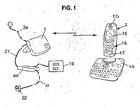
- This local radiocommunication network comprises a central base 1, generally fixed, and one or more peripherals 2 generally mobile and constituted for example by wireless portable telephone handsets.
- the central base 1 is connected to the network public telephone 3, generally via a wired link 3a constituting a private connection to said public telephone network and connected to a telephone line of this network.
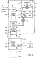
- connection 3a is connected to an interface circuit 4 (INT) which communicates bidirectionally with a central processing unit (BBP) or baseband processor ("BASE BAND PROCESSOR").
- BBP central processing unit
- BASE BAND PROCESSOR baseband processor
- the central unit 5 is generally also connected to an external memory 11 (EXT MEM) such as an EEPROM memory and a radio transmission and reception circuit 12 (E / R) itself. connected to one or more transmitting / receiving antennas 13, 14.
- EXT MEM external memory 11
- E / R radio transmission and reception circuit 12
- each peripheral 2 which communicates with the central base 1 by radio, also comprises a central unit (not shown) identical or similar to the central unit 5 of the central base 1, a radio circuit and antennas (no shown) identical or similar to those 12, 13, 14 of the central base 1, and optionally an external memory (not shown) identical or similar to that 11 of the central base 1.
- the central unit of each device 2 is connected to an output interface such as a screen 15 ( figure 1 ) and an input interface such as a keyboard 16, as well as a microphone 17 and a listener 17a.
- the device or devices 2 can of course conventionally be used to establish a voice communication, either with each other or with the outside via the public telecommunications network 3, but they can also be used to send or to consult alphanumeric messages. SMS type (corresponding for example to the ETSI ES 201 912 standard), for example as explained in the document FR-A-2,819,972 .
- peripherals 2 When the peripherals 2 are to be used to send alphanumeric messages, these alphanumeric messages can be entered into the peripherals 2 either by means of their own keyboard 16 or by connecting said peripherals to a more complete supplementary keyboard 18, as described, for example in the French patent application No. 02 07644 filed on June 20, 2002 by INVENTEL SYSTEMES.
- the alphanumeric messages in question are also used to make one or more external electronic devices 19 (DOM DEV.) Communicate, in particular home automation devices, with the outside and / or with the peripheral device (s). 2, through the central base 1.
- DOM DEV. external electronic devices 19
- each home automation apparatus 19 is connected to an external interface box 20 at the central base 1, by wire, by radio (according to a unidirectional or bidirectional radio communication protocol), by infra-red or the like, which interface box 20 is connected to to the power supply cable 21 of the central base 1.
- This power cable 21 connects the central base 1 to a power supply box 22 which connects to the network.
- alternating electric and which is generally adapted to produce a rectified periodic current of lower voltage than the current of the electrical network, at a frequency generally below 300 Hz, in particular of the order of 100 Hz when the network provides an AC voltage to 50 Hz.
- the power supply cable 21 comprises a connector 23 which is connected to an additional connector 24 of the central base 1.
- the power supply cable 21 comprises at least one live line 25 and a line 26 connected to the ground , the line 25 being connected by the connectors 23, 24 to a live line 27 inside the central base 1 while the line 26 is connected via the connectors 23 and 24 to a line 28 connected to the base inside the central base 1.
- the lines 27, 28 are connected to a power supply circuit 29 (CIRCLE SUPPLY) which supplies at least some of the electronic circuits of the central base 1.
- CIRCLE SUPPLY a power supply circuit 29 which supplies at least some of the electronic circuits of the central base 1.
- the power supply cable 21 could comprise several pairs of conductive lines possibly supplying several internal supply circuits to the central base 1, in which case the interface box 20 and its internal components could only be connected to one another. to one of these pairs of conductive lines and isolated from the others.
- the cable power supply 21 could comprise two pairs of conductive lines, including a pair of conductive lines reserved for, the power supply of a charger (not shown) integrated with the central base 1 and intended to recharge the batteries of the device 2, this pair of conductive lines being electrically isolated from the interface box components. 20.
- the interface box 20 communicates with the base. central 1 through two interface circuits 30, 31 (COM.) respectively belonging to the central base 1 and the interface housing 20.
- the interface circuit 30 is connected in shunt between the conductive lines 27, 28, while the interface circuit 31 is connected in shunt between the conductive lines 25, 26.
- These two interface circuits 30, 31 are adapted for exchanging messages in the form of modulated electrical signals, obtained by modulation (in particular amplitude modulation) of a carrier having a frequency preferably greater than 50 kHz and advantageously included between 100 and 500 kHz, which carrier is transmitted on the supply line formed by the live lines 25, 27.
- the emission of a bit equal to 0 by one of the two interface circuits 30, 31 may result in the transmission of the carrier on the live lines 25, 27, while the transmission of a bit equal to 1 may result in the absence of a carrier on the live lines 25, 27, it being understood that the interface circuits 30, 31 do not transmit any carrier when they have not been transmitted. no message to exchange between them.
- a low-pass filter is advantageously provided on the live line 27 between the interface circuit 30 and the supply circuit 29, this low-pass filter being advantageously constituted by an inductance L1, a value for example of the order of 100 ⁇ H; mounted in series on the conductive line 27.
- the interface box 20 may also include a low-pass filter between the interface circuit 31 and the power supply box 22, this low-pass filter may advantageously be constituted by an inductor L2, a waltzer for example of the order of 100 ⁇ H, arranged in series on the live line 25.
- Each of the interface circuits 30, 31 can advantageously be controlled by a serial interface controller, in particular a universal asynchronous transmitter / receiver (UART).
- a serial interface controller in particular a universal asynchronous transmitter / receiver (UART).
- the serial interface controller 32 of the base 1 communicates itself with the electronic central unit 5 of said base, while the serial interface controller 33 of the interface box 20 communicates with a microcontroller or microprocessor 34 (MC ) belonging to said interface box.
- This microcontroller 34 also communicates with the home automation device (s) 19.
- the interface circuit 30 may comprise an input / output terminal 35 connected to the live line 27, a clock signal input terminal 36 (CLOCK) connected to a clock signal output terminal of the serial interface controller 32, a data input terminal (UART-TX) connected to the data transmission terminal of the serial interface controller 32, and a data output terminal 38 (UART-RX) connected to the data receiving terminal of the serial interface controller 32.
- CLOCK clock signal input terminal 36
- UART-TX data input terminal
- UART-RX data output terminal 38
- the clock signal input terminal 36 is connected, via a resistor R1 (having for example a value of the order of 4.7 k ⁇ ), at the base of a PNP transistor Q1 (for example BC807 type).
- the emitter of this transistor is also connected to a power supply terminal at a DC voltage VCC equal for example to 3 volts, or if necessary to 5 volts, this power terminal being itself connected to a circuit DC power supply (not shown), which itself feeds via the live line 27.
- VCC DC voltage
- the base of the transistor Q1 is connected to the supply terminal VCC via a resistor R2 (for example of the order of 4.7 k ⁇ ), and the collector of the transistor Q1 is connected to the transmitter a PNP transistor Q2 (for example of type BC807).
- the collector of this transistor Q2 is connected to ground via a resistor R5 (for example of the order of 100 k ⁇ ), the emitter of which is connected to the data input terminal 37 by intermediate of a resistor R3 (for example of the order of 4.7 k ⁇ ), the base of the transistor Q2 being furthermore connected to the supply terminal VCC via a resistor R4 (equal to example of the order of 4.7 k ⁇ ).
- a resistor R5 for example of the order of 100 k ⁇
- the emitter of which is connected to the data input terminal 37 by intermediate of a resistor R3 (for example of the order of 4.7 k ⁇ )
- the base of the transistor Q2 being furthermore connected to the supply terminal VCC via a resistor R4 (equal to example of the order of 4.7 k ⁇ ).
- the collector of the transistor Q2 is also connected to the input / output terminal 35, via a capacitor C2 serving as a high-pass filter and being for example of the order of 10 nF.
- the transistor Q2 when the data input terminal 37 receives a high signal, corresponding to a bit equal to 1, the transistor Q2 is not on, so that no signal is transmitted to the input terminal / output 35, whereas when the data input terminal 37 receives a low signal, corresponding to a bit equal to 0, the transistor Q2 is on and passes the carrier received by the clock signal terminal 36, towards the input / output terminal 35.
- the emitter of the transistor Q3 is connected to ground and its collector is connected on the one hand to the data storage terminal 38 and on the other hand to the supply terminal VCC via a resistor R8 which can be of the order of 33 k ⁇ .
- a resistor R10 having a value of the order of 100 k ⁇ and connected to the supply terminal VCC (this value is valid for a supply voltage of 3 volts, and would advantageously be increased to about 150 k ⁇ for a supply voltage of 5 volts), and secondly, a resistance R9 connected to ground and having for example a value of about 33 kV. kW.
- Capacities C2 and C3 allow voltage variations of relatively low frequencies present on the live line 27 when it is powered by a rectified periodic voltage do not disturb the operation of the electronic components of the interface circuit 31.
- the capacitor C1 makes it possible to smooth the high frequency signal received from the input / output terminal 35 to transform it into a continuous signal when such a signal is present on the live line 27, so that the output terminal 38 transmits either a low signal or a high signal, depending on whether or not the high frequency carrier is present at the input / output terminal 35.
- the interface circuit 31 of the interface box 20 is moreover identical to the interface circuit 30 described above, except that its input / output terminal 35 is connected to the live line 25 and that its terminals 36, 37, 38 are connected to the corresponding terminals of the serial interface controller 33.
- the interface box 20 can be made to communicate with the central base 1 according to a conventional RS 232 serial protocol of the half-duplex type, the data being coded for example on 8 bits with a start bit and a bit of end.
- the serial interface controllers 32, 33 are also adapted to detect message collisions, that is to say the simultaneous transmission of messages by each of them, and to retransmit, with different delays, messages or messages. the parts of messages that were the subject of collisions.
- this interface box 20 can generate alphanumeric messages which are transmitted to the central base 1 and that the latter can, at least in certain cases, transform into messages SMS type, to send them to a recipient outside the local radio network, via the public network 3.
- the central base 1 can also transmit the alphanumeric messages from the interface box 20 to one or more peripherals 2 of the local radio network.
- this incoming alphanumeric message is recognized by the central unit 5 of the base station 1
- this message comprises a predetermined code that the electronic central unit 5 of the base 1 is adapted. to recognize.
- the alphanumeric message is identified as a so-called "service" message, intended for the interface box 20, and said alphanumeric message is transformed by the central base 1 into a message according to the serial communication protocol for transmitted to the serial interface controller 32 which then transmits corresponding signals to the interface circuit 30.
- This interface circuit 30 then generates corresponding modulated signals on the live lines 27, 25, so that these signals are received by the interface circuit 31, then transmitted to the serial interface controller 33, which controller serial interface 33 itself transmits this message to the microcontroller 34.
- said interface box 20 can then respond to it, in which case the microcontroller 34 generates a message intended to be retransmitted as an alphanumeric message SMS, which message is transmitted from firstly to the serial interface controller 33, then to the interface circuit 31, then to the interface circuit 30, to the serial interface controller 32 and finally to the electronic central unit 5 of the central base 1, which unit central electronic generates the alphanumeric SMS outgoing message (here said outgoing service message since from the interface box 20) to be transmitted to the public telecommunication network 3 or to one or more peripherals 2 of the local radio network.
- the microcontroller 34 When such an incoming service message has been transmitted to the interface box 20, said interface box 20 can then respond to it, in which case the microcontroller 34 generates a message intended to be retransmitted as an alphanumeric message SMS, which message is transmitted from firstly to the serial interface controller 33, then to the interface circuit 31, then to the interface circuit 30, to the serial interface controller 32 and finally to the electronic central unit 5 of the central base 1, which unit central electronic generates the alphan
- the messages transmitted according to the serial protocol between the central unit 1 and the interface box 20 can advantageously be transmitted in the form of predetermined frames.
- interface housing 20 instead of being mounted in series on the power supply cable 21, could be mounted as a bypass either on this cable, or on a specific connector for example to connect this cable at the central base 1.
- interface boxes 20 could be connected to the same central base 1 as previously described, and that several home automation devices 19 could communicate with each interface box 20.
Landscapes
- Engineering & Computer Science (AREA)
- Computer Networks & Wireless Communication (AREA)
- Signal Processing (AREA)
- Power Engineering (AREA)
- Mobile Radio Communication Systems (AREA)
- Sub-Exchange Stations And Push- Button Telephones (AREA)
- Transmitters (AREA)
Claims (14)
- Zentrale Basisstation (1) für ein privates lokales Funkkommunikationsnetzwerk, wobei diese zentrale Basisstation elektronische Schaltkreise aufweist, die eine elektronische Zentraleinheit (5) umfassen und über mindestens eine unter Spannung stehende Versorgungsleitung (27), die dazu bestimmt ist, an eine Außenquelle elektrischer Energie angeschlossen zu werden, elektrisch gespeist werden, wobei die zentrale Basisstation geeignet ist, einerseits mit einem öffentlichen Telekommunikationsnetzwerk (3) und andererseits mit mindestens einem Funkkommunikationsperipheriegerät (2) gemäß einem digitalen bidirektionalen Funkkommunikationsprotokoll für privates lokales Funkkommunikationsnetzwerk zu kommunizieren, wobei die Basisstation einen Schnittstellenschaltkreis (30) aufweist, der durch die elektronische Zentraleinheit (5) der zentralen Basisstation gesteuert wird und mit der Versorgungsleitung (27) verbunden ist, wobei dieser Schnittstellenschaltkreis geeignet ist, Nachrichten über die Versorgungsleitung zu senden und zu erfassen, und wobei der Schnittstellenschaltkreis (30) der zentralen Basisstation geeignet ist, gesendeten und erfassten Nachrichten repräsentative periodischer Hochfrequenzsignale zu senden und zu erfassen, und die zentrale Basisstation ein Tiefpassfilter (L1) aufweist, das geeignet ist, die periodischen Hochfrequenzsignale zwischen dem Schnittstellenschaltkreis (30) der zentralen Basisstation und mindestens einem Teil der elektronischen Schaltkreise der zentralen Basisstation zu filtern,
wobei die zentrale Basisstation geeignet ist, ausgehende alphanumerische Nachrichten mindestens an das öffentliche Telekommunikationsnetzwerk (3) zu senden und eingehende alphanumerische Nachrichten mindestens aus dem öffentlichen Telekommunikationsnetzwerk zu empfangen, wobei die elektronische Zentraleinheit (5) der zentralen Basisstation geeignet ist, (a) mindestens gewisse eingehende alphanumerische Nachrichten bzw. so genannte Dienstnachrichten, die für ein externes Schnittstellengehäuse (20) bestimmt sind, zu erkennen, und den Schnittstellenschaltkreis (30) der zentralen Basisstation zu veranlassen, auf der Versorgungsleitung (27) eine der jeweiligen eingehenden Dienstnachricht entsprechenden Nachricht zu erzeugen, und (b) festzulegen, wenn sie eine auf der Versorgungsleitung (27) von dem Schnittstellenschaltkreis (30) der zentralen Basisstation erfasste Nachricht empfängt, ob diese Nachricht nach außen zu übermitteln ist und in diesem Fall eine ausgehende alphanumerische Nachricht bzw. ausgehende Dienstnachricht, die der erfassten Nachricht entspricht, zu senden. - Zentrale Basisstation nach Anspruch 1, die ferner geeignet ist, ausgehende alphanumerische Nachrichten an mindestens ein Funkkommunikationsperipheriegerät (2) unter Verwendung des Funkkommunikationsprotokolls zu senden und eingehende alphanumerische Nachrichten aus dem Funkkommunikationsperipheriegerät zu empfangen.
- Zentrale Basisstation nach Anspruch 1 oder 2, bei welcher der Schnittstellenschaltkreis (30) der zentralen Basisstation in Abzweigung an der Versorgungsleitung angeordnet ist.
- Zentrale Basisstation nach einem beliebigen der vorhergehenden Ansprüche, bei welcher der Schnittstellenschaltkreis (30) der zentralen Basisstation geeignet ist, periodische Signale mit einer Frequenz zwischen 100 und 500 kHz zu senden und zu erfassen.
- Zentrale Basisstation nach einem beliebigen der vorhergehenden Ansprüche, bei welcher der Schnittstellenschaltkreis (30) der zentralen Basisstation durch die elektronische Zentraleinheit (5) der zentralen Basisstation über einen seriellen Schnittstellencontroller (32) gesteuert wird.
- Funkkommunikationssystem mit einer zentralen Basisstation (1) gemäß einem beliebigen der vorhergehenden Ansprüche und einem externen Schnittstellengehäuse (20), das sich von der zentralen Basisstation unterscheidet und selbst Folgendes umfasst: eine elektronische Zentraleinheit (34) und einen Schnittstellenschaltkreis (31), der durch die elektronische Zentraleinheit des externen Schnittstellengehäuses gesteuert wird und mit der Versorgungsleitung (25, 27) verbunden ist, wobei dieser Schnittstellenschaltkreis (31) des externen Schnittstellengehäuses geeignet ist, mit dem Schnittstellenschaltkreis (30) der zentralen Basisstation zu kommunizieren, indem Nachrichten über die Versorgungsleitung (25, 27) gesendet und erfasst werden.
- Funkkommunikationssystem nach Anspruch 6, bei dem der Schnittstellenschaltkreis (31) des externen Schnittstellengehäuses in Abzweigung an der Versorgungsleitung (25, 27) angeordnet ist.
- Funkkommunikationssystem nach Anspruch 6 oder nach Anspruch 7, bei dem der Schnittstellenschaltkreis (31) des externen Schnittstellengehäuses geeignet ist, periodische, für gesendete und erfasste repräsentative Hochfrequenzsignale zu senden und zu erfassen und das externe Schnittstellengehäuse (20) ein Tiefpassfilter (L2) aufweist, das geeignet ist, die periodischen Hochfrequenzsignale zwischen dem Schnittstellenschaltkreis (31) des externen Schnittstellengehäuses und einer elektrischen Versorgungsvorrichtung (22) zu filtern, welche dazu bestimmt ist, die Versorgungsleitung (25, 27) mit der Außenquelle elektrischer Energie zu verbinden.
- Funkkommunikationssystem nach Anspruch 6, bei dem der Schnittstellenschaltkreis (31) des externen Schnittstellengehäuses geeignet ist, periodische Signale mit einer Frequenz zwischen 100 und 500 kHz zu senden und zu erfassen.
- Funkkommunikationssystem nach einem beliebigen der Ansprüche 6 bis 9, bei dem der Schnittstellenschaltkreis (31) des externen Schnittstellengehäuses durch die elektronische Zentraleinheit (34) des externen Schnittstellengehäuses über einen seriellen Schnittstellencontroller (33) gesteuert wird.
- Funkkommunikationssystem nach einem beliebigen der Ansprüche 6 bis 10, bei dem die zentrale Basisstation (1) und das externe Schnittstellengehäuse (20) geeignet sind, zusammen gemäß einem asynchronen Halbduplexprotokoll zu kommunizieren.
- Funkkommunikationssystem nach einem beliebigen der Ansprüche 6 bis 11, umfassend ferner ein elektronisches Außengerät (19), das sich von dem externen Schnittstellengehäuse (20) unterscheidet und mit der elektronischen Zentraleinheit (31) des externen Schnittstellengehäuses kommuniziert.
- Funkkommunikationssystem nach Anspruch 12, bei dem das elektronische Außengerät (19) unter einem Sensor, einem Aktuator und einer zentralisierten Steuerungsvorrichtung, die geeignet ist, mit einer Vielzahl von Sensoren und Aktuatoren verbunden zu werden, gewählt ist.
- Funkkommunikationssystem nach einem beliebigen der Ansprüche 6 bis 13, mit einer zentralen Basisstation (1) nach Anspruch 1 und bei dem die elektronische Zentraleinheit (34) des externen Schnittstellengehäuses (20) geeignet ist, den Schnittstellenschaltkreis (31) des externen Schnittstellengehäuses zu veranlassen, auf der Versorgungsleitung (25, 27) Nachrichten zu erzeugen, die dazu bestimmt sind, von der zentralen Basisstation (1) als ausgehende Dienstnachrichten gesendet zu werden.
Applications Claiming Priority (3)
| Application Number | Priority Date | Filing Date | Title |
|---|---|---|---|
| FR0210887 | 2002-09-03 | ||
| FR0210887A FR2844125B1 (fr) | 2002-09-03 | 2002-09-03 | Base centrale pour reseau local de radiocommunication prive et dispositif de radiocommunication incluant une telle base. |
| PCT/FR2003/002628 WO2004023768A1 (fr) | 2002-09-03 | 2003-09-02 | Base centrale pour reseau local de radiocommunication prive et dispositif de radiocommunication incluant une telle base |
Publications (2)
| Publication Number | Publication Date |
|---|---|
| EP1535451A1 EP1535451A1 (de) | 2005-06-01 |
| EP1535451B1 true EP1535451B1 (de) | 2012-03-21 |
Family
ID=31503073
Family Applications (1)
| Application Number | Title | Priority Date | Filing Date |
|---|---|---|---|
| EP03769555A Expired - Lifetime EP1535451B1 (de) | 2002-09-03 | 2003-09-02 | Basisstation für privates lokales fünkkommunikationsnetzwerk und fünkkommunikationssystem mit einer solchen basisstation |
Country Status (7)
| Country | Link |
|---|---|
| US (1) | US20060035650A1 (de) |
| EP (1) | EP1535451B1 (de) |
| AT (1) | ATE550868T1 (de) |
| ES (1) | ES2382544T3 (de) |
| FR (1) | FR2844125B1 (de) |
| PT (1) | PT1535451E (de) |
| WO (1) | WO2004023768A1 (de) |
Families Citing this family (4)
| Publication number | Priority date | Publication date | Assignee | Title |
|---|---|---|---|---|
| US7519789B1 (en) * | 2005-01-20 | 2009-04-14 | National Semiconductor Corporation | Method and system for dynamically selecting a clock edge for read data recovery |
| CN101208312A (zh) * | 2005-06-27 | 2008-06-25 | 西科尔公司 | 用于合成阿那曲唑及纯化一种阿那曲唑中间体的方法 |
| US8285326B2 (en) * | 2005-12-30 | 2012-10-09 | Honeywell International Inc. | Multiprotocol wireless communication backbone |
| FR2930093A1 (fr) * | 2008-04-10 | 2009-10-16 | Somfy Sas | Dispositif de type emetteur et/ou recepteur de signaux radioelectriques |
Family Cites Families (18)
| Publication number | Priority date | Publication date | Assignee | Title |
|---|---|---|---|---|
| US4701945A (en) * | 1984-10-09 | 1987-10-20 | Pedigo Michael K | Carrier current transceiver |
| US5337044A (en) * | 1991-10-08 | 1994-08-09 | Nomadic Systems, Inc. | System for remote computer control using message broadcasting system |
| JP2749248B2 (ja) * | 1993-07-28 | 1998-05-13 | ローム株式会社 | コードレス電話機 |
| NL9400239A (nl) * | 1994-02-17 | 1995-10-02 | Grid Telecom Systems Bv | Huistelefoonsysteem. |
| US5787360A (en) * | 1995-08-09 | 1998-07-28 | Hewlett-Packard Company | Telecommunications systems |
| US6836655B1 (en) * | 1995-08-31 | 2004-12-28 | Telemac Corporation | Secure interlink receiver for remote programming of wireless telephones |
| US6324270B1 (en) * | 1998-07-13 | 2001-11-27 | Qwest Communications Int'l., Inc. | System for coordination of electronic devices |
| EP1076443A1 (de) * | 1999-08-13 | 2001-02-14 | Alcatel | Verfahren zum Verbindungsaufbau zwischen einem schnurlos Endgerät und einem anderen externen Endgerät, mit einem Analognetz und einem Elektrizitätsnetz |
| GB2358771B (en) * | 2000-01-27 | 2003-08-06 | Phillip Jarrett | Multi-purpose mobile cordless phone system |
| GB2368222B (en) * | 2000-10-17 | 2003-02-19 | Ericsson Telefon Ab L M | Method and telecommunications network for controlling an external device |
| EP1202544A1 (de) * | 2000-10-30 | 2002-05-02 | Telefonaktiebolaget L M Ericsson (Publ) | System und Verfahren zur Verteilung von Sprache und Daten |
| US7313423B2 (en) * | 2000-11-07 | 2007-12-25 | Research In Motion Limited | Communication device with multiple detachable communication modules |
| US6947736B2 (en) * | 2001-11-20 | 2005-09-20 | Texas Instruments Incorporated | Universal broadband home network for scalable IEEE 802.11 based wireless and wireline networking |
| US7573891B1 (en) * | 2001-12-05 | 2009-08-11 | Optimal Innovations, Inc. | Hybrid fiber/conductor integrated communication networks |
| KR20040078147A (ko) * | 2002-01-29 | 2004-09-08 | 코닌클리케 필립스 일렉트로닉스 엔.브이. | 스위치가능한 차단 주파수를 갖는 저역 통과 필터 및 노치필터를 포함하는 고속 세틀링 데이터 슬라이서 |
| KR100434292B1 (ko) * | 2002-02-28 | 2004-06-05 | 엘지전자 주식회사 | 홈 네트워크 시스템 |
| FR2841350B1 (fr) * | 2002-06-20 | 2004-12-10 | Inventel Systemes | Dispositif comprenant un appareil electronique portable et un appareil d'entree de donnees |
| US6727804B1 (en) * | 2002-07-23 | 2004-04-27 | Domosys Corporation | Power line communication system and method |
-
2002
- 2002-09-03 FR FR0210887A patent/FR2844125B1/fr not_active Expired - Fee Related
-
2003
- 2003-09-02 EP EP03769555A patent/EP1535451B1/de not_active Expired - Lifetime
- 2003-09-02 US US10/526,707 patent/US20060035650A1/en not_active Abandoned
- 2003-09-02 AT AT03769555T patent/ATE550868T1/de active
- 2003-09-02 PT PT03769555T patent/PT1535451E/pt unknown
- 2003-09-02 WO PCT/FR2003/002628 patent/WO2004023768A1/fr not_active Ceased
- 2003-09-02 ES ES03769555T patent/ES2382544T3/es not_active Expired - Lifetime
Also Published As
| Publication number | Publication date |
|---|---|
| PT1535451E (pt) | 2012-05-11 |
| ATE550868T1 (de) | 2012-04-15 |
| EP1535451A1 (de) | 2005-06-01 |
| FR2844125A1 (fr) | 2004-03-05 |
| US20060035650A1 (en) | 2006-02-16 |
| FR2844125B1 (fr) | 2004-12-17 |
| WO2004023768A1 (fr) | 2004-03-18 |
| ES2382544T3 (es) | 2012-06-11 |
Similar Documents
| Publication | Publication Date | Title |
|---|---|---|
| US5315645A (en) | Communication apparatus utilizing digital optical signals | |
| JP4454907B2 (ja) | テレビドアホンシステム | |
| US7626489B2 (en) | Power line communications device and method | |
| US7436321B2 (en) | Power line communication system with automated meter reading | |
| US7174176B1 (en) | Cordless security system and method | |
| CA2352061C (en) | Method and system for combining wireless phone jack and rf wireless communications | |
| EP0115362B1 (de) | Anordnung zur Fernsprechverbindung durch Funkverbindung | |
| US20050168326A1 (en) | Power line repeater system and method | |
| WO2012018526A1 (en) | Improved high bandwidth data transport system for use in a smartgrid | |
| JP2005512387A (ja) | 家庭用電気機器ネットワーク | |
| CN1423861A (zh) | 高可靠的电力线通信系统 | |
| FR2794588A1 (fr) | Systeme local combine de telephonie et d'alarme | |
| EP1535451B1 (de) | Basisstation für privates lokales fünkkommunikationsnetzwerk und fünkkommunikationssystem mit einer solchen basisstation | |
| JP2013134602A (ja) | 通信システム、ネットワークストレージ、サーバ装置及びプログラム | |
| CA2805973A1 (fr) | Module de gestion de candelabres et de services et systeme de telegestion comportant au moins un tel module | |
| EP0333172A1 (de) | Fernüberwachungsanordnung auf einem Fernsprechkanal für Einzel- oder Mehrzweck-Analogen | |
| EP2136452A2 (de) | System zur Überwachung der Stromeinspeisung in ein elektrisches Gerät und kommunikationsfähige elektrische Steckdose für ein solches System | |
| KR100824261B1 (ko) | 일반전화기의 문자메시지를 이용한 전자제품 제어 및상태감시 시스템 | |
| EP0119163A2 (de) | Verfahren und Anlage zur Nachrichtenübertragung über das Niederspannungsnetz der elektrischen Energieverteilung und Anwendung | |
| EP3816957A1 (de) | Sicherheits- und überwachungssystem und sein funktionsverfahren | |
| KR20010103938A (ko) | 휴대용 무선 전화를 이용한 개선된 원격 감시 장치 | |
| WO2009145922A1 (en) | Handheld cellular telephone conversion system for home telephone network compatibility | |
| FR2842693A1 (fr) | Dispositif automatique de retransmission d'informations | |
| FR2695494A1 (fr) | Centrale domotique multifonctions modulaire. | |
| JPH0697993A (ja) | コードレス電話装置 |
Legal Events
| Date | Code | Title | Description |
|---|---|---|---|
| PUAI | Public reference made under article 153(3) epc to a published international application that has entered the european phase |
Free format text: ORIGINAL CODE: 0009012 |
|
| 17P | Request for examination filed |
Effective date: 20050228 |
|
| AK | Designated contracting states |
Kind code of ref document: A1 Designated state(s): AT BE BG CH CY CZ DE DK EE ES FI FR GB GR HU IE IT LI LU MC NL PT RO SE SI SK TR |
|
| RIN1 | Information on inventor provided before grant (corrected) |
Inventor name: OLIVIER, HENRI-NICOLAS Inventor name: AMBERNY, OLIVIER Inventor name: CARREEL, ERIC Inventor name: DEGUET, BRUNO |
|
| 17Q | First examination report despatched |
Effective date: 20110325 |
|
| GRAP | Despatch of communication of intention to grant a patent |
Free format text: ORIGINAL CODE: EPIDOSNIGR1 |
|
| RTI1 | Title (correction) |
Free format text: CENTRAL BASE FOR PRIVATE RADIOCOMMUNICATION LOCAL NETWORK AND RADIOCOMMUNICATION SYSTEM COMPRISING THE SAME |
|
| GRAS | Grant fee paid |
Free format text: ORIGINAL CODE: EPIDOSNIGR3 |
|
| GRAA | (expected) grant |
Free format text: ORIGINAL CODE: 0009210 |
|
| AK | Designated contracting states |
Kind code of ref document: B1 Designated state(s): AT BE BG CH CY CZ DE DK EE ES FI FR GB GR HU IE IT LI LU MC NL PT RO SE SI SK TR |
|
| REG | Reference to a national code |
Ref country code: GB Ref legal event code: FG4D Free format text: NOT ENGLISH |
|
| REG | Reference to a national code |
Ref country code: CH Ref legal event code: EP |
|
| REG | Reference to a national code |
Ref country code: IE Ref legal event code: FG4D Free format text: LANGUAGE OF EP DOCUMENT: FRENCH |
|
| REG | Reference to a national code |
Ref country code: AT Ref legal event code: REF Ref document number: 550868 Country of ref document: AT Kind code of ref document: T Effective date: 20120415 |
|
| REG | Reference to a national code |
Ref country code: PT Ref legal event code: SC4A Free format text: AVAILABILITY OF NATIONAL TRANSLATION Effective date: 20120430 |
|
| REG | Reference to a national code |
Ref country code: DE Ref legal event code: R096 Ref document number: 60340361 Country of ref document: DE Effective date: 20120516 Ref country code: NL Ref legal event code: T3 |
|
| REG | Reference to a national code |
Ref country code: ES Ref legal event code: FG2A Ref document number: 2382544 Country of ref document: ES Kind code of ref document: T3 Effective date: 20120611 |
|
| PG25 | Lapsed in a contracting state [announced via postgrant information from national office to epo] |
Ref country code: FI Free format text: LAPSE BECAUSE OF FAILURE TO SUBMIT A TRANSLATION OF THE DESCRIPTION OR TO PAY THE FEE WITHIN THE PRESCRIBED TIME-LIMIT Effective date: 20120321 Ref country code: GR Free format text: LAPSE BECAUSE OF FAILURE TO SUBMIT A TRANSLATION OF THE DESCRIPTION OR TO PAY THE FEE WITHIN THE PRESCRIBED TIME-LIMIT Effective date: 20120622 |
|
| PG25 | Lapsed in a contracting state [announced via postgrant information from national office to epo] |
Ref country code: CY Free format text: LAPSE BECAUSE OF FAILURE TO SUBMIT A TRANSLATION OF THE DESCRIPTION OR TO PAY THE FEE WITHIN THE PRESCRIBED TIME-LIMIT Effective date: 20120321 |
|
| PG25 | Lapsed in a contracting state [announced via postgrant information from national office to epo] |
Ref country code: EE Free format text: LAPSE BECAUSE OF FAILURE TO SUBMIT A TRANSLATION OF THE DESCRIPTION OR TO PAY THE FEE WITHIN THE PRESCRIBED TIME-LIMIT Effective date: 20120321 Ref country code: RO Free format text: LAPSE BECAUSE OF FAILURE TO SUBMIT A TRANSLATION OF THE DESCRIPTION OR TO PAY THE FEE WITHIN THE PRESCRIBED TIME-LIMIT Effective date: 20120321 Ref country code: CZ Free format text: LAPSE BECAUSE OF FAILURE TO SUBMIT A TRANSLATION OF THE DESCRIPTION OR TO PAY THE FEE WITHIN THE PRESCRIBED TIME-LIMIT Effective date: 20120321 Ref country code: SE Free format text: LAPSE BECAUSE OF FAILURE TO SUBMIT A TRANSLATION OF THE DESCRIPTION OR TO PAY THE FEE WITHIN THE PRESCRIBED TIME-LIMIT Effective date: 20120321 Ref country code: SI Free format text: LAPSE BECAUSE OF FAILURE TO SUBMIT A TRANSLATION OF THE DESCRIPTION OR TO PAY THE FEE WITHIN THE PRESCRIBED TIME-LIMIT Effective date: 20120321 |
|
| PG25 | Lapsed in a contracting state [announced via postgrant information from national office to epo] |
Ref country code: SK Free format text: LAPSE BECAUSE OF FAILURE TO SUBMIT A TRANSLATION OF THE DESCRIPTION OR TO PAY THE FEE WITHIN THE PRESCRIBED TIME-LIMIT Effective date: 20120321 |
|
| PLBE | No opposition filed within time limit |
Free format text: ORIGINAL CODE: 0009261 |
|
| STAA | Information on the status of an ep patent application or granted ep patent |
Free format text: STATUS: NO OPPOSITION FILED WITHIN TIME LIMIT |
|
| PG25 | Lapsed in a contracting state [announced via postgrant information from national office to epo] |
Ref country code: DK Free format text: LAPSE BECAUSE OF FAILURE TO SUBMIT A TRANSLATION OF THE DESCRIPTION OR TO PAY THE FEE WITHIN THE PRESCRIBED TIME-LIMIT Effective date: 20120321 |
|
| 26N | No opposition filed |
Effective date: 20130102 |
|
| PG25 | Lapsed in a contracting state [announced via postgrant information from national office to epo] |
Ref country code: IT Free format text: LAPSE BECAUSE OF FAILURE TO SUBMIT A TRANSLATION OF THE DESCRIPTION OR TO PAY THE FEE WITHIN THE PRESCRIBED TIME-LIMIT Effective date: 20120321 |
|
| BERE | Be: lapsed |
Owner name: INVENTEL SYSTEMES Effective date: 20120930 |
|
| REG | Reference to a national code |
Ref country code: DE Ref legal event code: R097 Ref document number: 60340361 Country of ref document: DE Effective date: 20130102 |
|
| PG25 | Lapsed in a contracting state [announced via postgrant information from national office to epo] |
Ref country code: MC Free format text: LAPSE BECAUSE OF NON-PAYMENT OF DUE FEES Effective date: 20120930 |
|
| REG | Reference to a national code |
Ref country code: CH Ref legal event code: PL |
|
| REG | Reference to a national code |
Ref country code: IE Ref legal event code: MM4A |
|
| PG25 | Lapsed in a contracting state [announced via postgrant information from national office to epo] |
Ref country code: BG Free format text: LAPSE BECAUSE OF FAILURE TO SUBMIT A TRANSLATION OF THE DESCRIPTION OR TO PAY THE FEE WITHIN THE PRESCRIBED TIME-LIMIT Effective date: 20120621 Ref country code: BE Free format text: LAPSE BECAUSE OF NON-PAYMENT OF DUE FEES Effective date: 20120930 Ref country code: LI Free format text: LAPSE BECAUSE OF NON-PAYMENT OF DUE FEES Effective date: 20120930 Ref country code: CH Free format text: LAPSE BECAUSE OF NON-PAYMENT OF DUE FEES Effective date: 20120930 Ref country code: IE Free format text: LAPSE BECAUSE OF NON-PAYMENT OF DUE FEES Effective date: 20120902 |
|
| PG25 | Lapsed in a contracting state [announced via postgrant information from national office to epo] |
Ref country code: TR Free format text: LAPSE BECAUSE OF FAILURE TO SUBMIT A TRANSLATION OF THE DESCRIPTION OR TO PAY THE FEE WITHIN THE PRESCRIBED TIME-LIMIT Effective date: 20120321 |
|
| PG25 | Lapsed in a contracting state [announced via postgrant information from national office to epo] |
Ref country code: LU Free format text: LAPSE BECAUSE OF NON-PAYMENT OF DUE FEES Effective date: 20120902 |
|
| PG25 | Lapsed in a contracting state [announced via postgrant information from national office to epo] |
Ref country code: HU Free format text: LAPSE BECAUSE OF FAILURE TO SUBMIT A TRANSLATION OF THE DESCRIPTION OR TO PAY THE FEE WITHIN THE PRESCRIBED TIME-LIMIT Effective date: 20030902 |
|
| REG | Reference to a national code |
Ref country code: GB Ref legal event code: 732E Free format text: REGISTERED BETWEEN 20150305 AND 20150311 |
|
| REG | Reference to a national code |
Ref country code: FR Ref legal event code: PLFP Year of fee payment: 13 |
|
| PGFP | Annual fee paid to national office [announced via postgrant information from national office to epo] |
Ref country code: ES Payment date: 20150810 Year of fee payment: 13 Ref country code: DE Payment date: 20150924 Year of fee payment: 13 Ref country code: PT Payment date: 20150901 Year of fee payment: 13 Ref country code: GB Payment date: 20150924 Year of fee payment: 13 |
|
| PGFP | Annual fee paid to national office [announced via postgrant information from national office to epo] |
Ref country code: AT Payment date: 20150825 Year of fee payment: 13 Ref country code: FR Payment date: 20150917 Year of fee payment: 13 |
|
| PGFP | Annual fee paid to national office [announced via postgrant information from national office to epo] |
Ref country code: NL Payment date: 20150909 Year of fee payment: 13 |
|
| REG | Reference to a national code |
Ref country code: DE Ref legal event code: R119 Ref document number: 60340361 Country of ref document: DE |
|
| REG | Reference to a national code |
Ref country code: NL Ref legal event code: MM Effective date: 20161001 |
|
| REG | Reference to a national code |
Ref country code: AT Ref legal event code: MM01 Ref document number: 550868 Country of ref document: AT Kind code of ref document: T Effective date: 20160902 |
|
| GBPC | Gb: european patent ceased through non-payment of renewal fee |
Effective date: 20160902 |
|
| PG25 | Lapsed in a contracting state [announced via postgrant information from national office to epo] |
Ref country code: PT Free format text: LAPSE BECAUSE OF NON-PAYMENT OF DUE FEES Effective date: 20170302 |
|
| PG25 | Lapsed in a contracting state [announced via postgrant information from national office to epo] |
Ref country code: NL Free format text: LAPSE BECAUSE OF NON-PAYMENT OF DUE FEES Effective date: 20161001 |
|
| REG | Reference to a national code |
Ref country code: FR Ref legal event code: ST Effective date: 20170531 |
|
| PG25 | Lapsed in a contracting state [announced via postgrant information from national office to epo] |
Ref country code: DE Free format text: LAPSE BECAUSE OF NON-PAYMENT OF DUE FEES Effective date: 20170401 Ref country code: GB Free format text: LAPSE BECAUSE OF NON-PAYMENT OF DUE FEES Effective date: 20160902 Ref country code: FR Free format text: LAPSE BECAUSE OF NON-PAYMENT OF DUE FEES Effective date: 20160930 |
|
| PG25 | Lapsed in a contracting state [announced via postgrant information from national office to epo] |
Ref country code: AT Free format text: LAPSE BECAUSE OF NON-PAYMENT OF DUE FEES Effective date: 20160902 |
|
| PG25 | Lapsed in a contracting state [announced via postgrant information from national office to epo] |
Ref country code: ES Free format text: LAPSE BECAUSE OF NON-PAYMENT OF DUE FEES Effective date: 20160903 |
|
| REG | Reference to a national code |
Ref country code: ES Ref legal event code: FD2A Effective date: 20181128 |