EP1536112A1 - Metallträger - Google Patents
Metallträger Download PDFInfo
- Publication number
- EP1536112A1 EP1536112A1 EP04028016A EP04028016A EP1536112A1 EP 1536112 A1 EP1536112 A1 EP 1536112A1 EP 04028016 A EP04028016 A EP 04028016A EP 04028016 A EP04028016 A EP 04028016A EP 1536112 A1 EP1536112 A1 EP 1536112A1
- Authority
- EP
- European Patent Office
- Prior art keywords
- radius
- metal
- metal sheet
- crest
- catalyst
- Prior art date
- Legal status (The legal status is an assumption and is not a legal conclusion. Google has not performed a legal analysis and makes no representation as to the accuracy of the status listed.)
- Granted
Links
Images


Classifications
-
- F—MECHANICAL ENGINEERING; LIGHTING; HEATING; WEAPONS; BLASTING
- F01—MACHINES OR ENGINES IN GENERAL; ENGINE PLANTS IN GENERAL; STEAM ENGINES
- F01N—GAS-FLOW SILENCERS OR EXHAUST APPARATUS FOR MACHINES OR ENGINES IN GENERAL; GAS-FLOW SILENCERS OR EXHAUST APPARATUS FOR INTERNAL-COMBUSTION ENGINES
- F01N3/00—Exhaust or silencing apparatus having means for purifying, rendering innocuous, or otherwise treating exhaust
- F01N3/08—Exhaust or silencing apparatus having means for purifying, rendering innocuous, or otherwise treating exhaust for rendering innocuous
- F01N3/10—Exhaust or silencing apparatus having means for purifying, rendering innocuous, or otherwise treating exhaust for rendering innocuous by thermal or catalytic conversion of noxious components of exhaust
- F01N3/24—Exhaust or silencing apparatus having means for purifying, rendering innocuous, or otherwise treating exhaust for rendering innocuous by thermal or catalytic conversion of noxious components of exhaust characterised by constructional aspects of converting apparatus
- F01N3/28—Construction of catalytic reactors
- F01N3/2803—Construction of catalytic reactors characterised by structure, by material or by manufacturing of catalyst support
- F01N3/2807—Metal other than sintered metal
- F01N3/281—Metallic honeycomb monoliths made of stacked or rolled sheets, foils or plates
-
- B—PERFORMING OPERATIONS; TRANSPORTING
- B01—PHYSICAL OR CHEMICAL PROCESSES OR APPARATUS IN GENERAL
- B01J—CHEMICAL OR PHYSICAL PROCESSES, e.g. CATALYSIS OR COLLOID CHEMISTRY; THEIR RELEVANT APPARATUS
- B01J35/00—Catalysts, in general, characterised by their form or physical properties
- B01J35/50—Catalysts, in general, characterised by their form or physical properties characterised by their shape or configuration
- B01J35/56—Foraminous structures having flow-through passages or channels, e.g. grids or three-dimensional [3D] monoliths
- B01J35/57—Honeycombs
-
- Y—GENERAL TAGGING OF NEW TECHNOLOGICAL DEVELOPMENTS; GENERAL TAGGING OF CROSS-SECTIONAL TECHNOLOGIES SPANNING OVER SEVERAL SECTIONS OF THE IPC; TECHNICAL SUBJECTS COVERED BY FORMER USPC CROSS-REFERENCE ART COLLECTIONS [XRACs] AND DIGESTS
- Y10—TECHNICAL SUBJECTS COVERED BY FORMER USPC
- Y10T—TECHNICAL SUBJECTS COVERED BY FORMER US CLASSIFICATION
- Y10T29/00—Metal working
- Y10T29/49—Method of mechanical manufacture
- Y10T29/49345—Catalytic device making
Definitions
- the present invention relates to a metal carrier for catalytic converter provided in an exhaust system of an internal combustion engine and the like.
- An exhaust system for an internal combustion engine or the like is provided with a catalytic converter which cleans emissions.
- This kind of catalytic converter generally uses metal carrier having metal sheet such as Fe-Cr-Al based ferrite stainless foil as the catalytic converter.
- metal sheet corrugated plates and metal sheet flat plates are alternately stacked on one another. These stacked plates are wound many times, forming a core having a honeycomb structure.
- the structure has a circular cross section and the like.
- a lower-corrugated plate having lower corrugation height than that of the corrugated plate may be used as the flat plate.
- a brazing foil material is wound around an outer periphery of the core, it is press-fitted into a metal outer cylinder, and this is heated in a vacuum. With this heating operation, crests of the corrugated plate and the flat plate are joined to each other using diffusion joining, and the outer cylinder and the core are brazed to each other.
- Catalyst such as platinum is added to the core, diffusers are welded to both ends of the outer cylinder, thereby forming a catalytic converter.
- wash coat solution containing catalyst is poured into the core, and a thin membrane containing the catalyst is formed on the surface of the core. See Japanese Patent Applications Laid-open Nos. 2000-61317 and No. 2003-334456.
- the metal carrier has a joint portion between the corrugated plate and the flat plate (or low-corrugated plate).
- the joint portion has a fillet (catalyst residue) produced from the wash coat solution under surface tension.
- This fillet is determined by the plate material, air (atmosphere), the surface tension of the solution and the like.
- the fillet is formed such as to draw an arc, and has large thickness. This prevents catalyst contained in the fillet from exhibiting the original performance, and the catalyst is waste.
- the first aspect of the invention provides the following metal carrier.
- the metal carrier includes a core having a thinned film containing a metal catalyst.
- the core includes a first metal sheet corrugated and having a crest with a first radius.
- the core includes a second metal sheet flattened or corrugated smaller in corrugation height than the first metal sheet.
- the first and second metal sheets are stacked on each other and are wound up.
- the crest and second metal sheet are joined to each other, having a joint therebetween.
- a fillet of the catalyst is formed between the joint, the first metal sheet, and the second metal sheet, having an arced surface of a second radius extending between the first and second metal sheets.
- the first radius is set substantially equal to the second radius.
- the first radius may be an inner radius of the crest.
- the first radius may be 1.0 to 1.2 times of the second radius.
- the second aspect of the invention provides the following metal carrier.
- the metal carrier includes a core having a thinned film containing a metal catalyst.
- the core includes a first metal sheet corrugated and having a crest of a first radius.
- the core includes a second metal sheet flattened or corrugated smaller in corrugation height than the first metal sheet.
- the first and second metal sheets are stacked on each other and are wound up.
- the crest and second metal sheet are joined to each other, having a joint therebetween.
- a fillet of the catalyst is formed between the joint, the first metal sheet, and the second metal sheet, having an arced surface of a second average radius extending between the first and second metal sheets.
- the first radius is set to the second average radius with a standard deviation ( ⁇ ) or more.
- the first metal sheet has a vertical wall set to be substantially normal to the second metal sheet.
- the first metal sheet may have a corrugation height between a crest and a trough thereof and a corrugation pitch between neighboring crests.
- the corrugation height may be greater than the corrugation pitch.
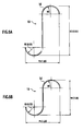
- a metal carrier 10A includes a corrugated plate 1A as a first metal sheet and a flat sheet 2 as a second metal sheet of a thinned metal plate in a band-shape.
- the corrugated plate 1A and the flat plate 2 are composed with Al of around 5%, Cu of around 20%, in addition, minute amount of metal Mn, Mo and the like, and the remains of Fe.
- the thickness of plate 1A or 2 is 20 to 50 ⁇ m.
- the corrugated plate 1A and the flat plate 2 are alternately stacked on one another, forming a layered product.
- the layered product is wound many times, forming a core 3 having a honeycomb structure.
- the honeycomb structure has a circular cross section for example.
- Wash coat solution containing catalyst such as platinum is poured into the core 3, forming a thin membrane containing the catalyst on the surface of the core 3.
- the catalyst contains a main component of alumina (Al 2 O 3 ) with another minute amount of cerium oxide (CeO 2 ) or barium oxide or the like, which contains Pt, Pd, or Rh.
- Diffusers (not shown) are welded to both ends of the outer cylinder 4, forming a catalytic converter.
- the corrugated plate 1A has thickness of 30 ⁇ m, corrugation height H1 of 2.0mm, and corrugation pitch P1 of 1.6mm.
- the corrugation height is a distance between the trough and the crest of a corrugation.
- the corrugation pitch is a distance between neighboring crests or between neighboring troughs of a corrugation.
- the corrugated plate 1A has crests 1a, 1b, and 1c whose radii R1, R2, and R3 are 0.2mm. 0.3mm, and 0.4mm, respectively.
- the cross section areas of fillets 5a, 5b, and 5c are 55, 65, and 90, respectively.
- numeric values are comparative values when a cross section area of a fillet 103 of a comparative example shown in Fig. 4 is set to 100.
- the corrugated plate 101 is interposed between two flat plates 102.
- the corrugated plate 101 has corrugation height H2 of 1.2mm, pitch P2 of 2.56mm, and crest radius R4 of 0.55mm.
- Each of the fillets 5a, 5b, and 5c has radius r1 of 0.25mm.
- a crest 1a having radius R1 of 0.2mm produces a catalyst residue inside the crest 1a.
- the crest 1c having radius R4 of 0.4mm does not produce a catalyst residue inside of the crest 1a.
- the fillet 5c is greater in area than the fillet 5a having the radius R1 of 0.2mm.
- the crest 1b having radius R2 of 0. 3mm produces little catalyst residue inside the crest 1b.
- the fillet 5b is smaller in area than the fillet 5c in correspondence with radius R3, and greater than the fillet 5a.
- the crest 1b reduces a total amount of waste catalyst as compared with the crests 5a and 5c of radius R1 and R3.
- the radii R1, R2, and R3 are outer radii of the crests 1a, 1b, and 1c, respectively.
- the inner radii of the crests 1a, 1b, and 1c are smaller than the radii R1, R2, and R3.
- the inner radius of the crest 1a having the radius R2 is 0.27mm (-0.3mm - 0. 03mm), which is substantially equal to the radius r1 of the arc, or arced surface, of the fillet 5b.
- the determination of inner radius of the crest 1a as a reference eliminates the influence due to the thickness of the corrugated plate 1, reducing the amount of the catalyst residue with higher accuracy.
- the inner radius of the crest 1a may not be completely equal to the radius r1.
- the inner radius is 0.8 to 1.2 times of the radius r1.
- the inner radius may be 1.0 to 1.2 times of the radius r1.
- the stacked corrugated plates, flat plates, and metal carrier 10A are described.
- the flat plate 2 may be replaced by a lower-corrugated plate with a lower corrugation height.
- the lower-corrugated plate and the corrugated plate 1 may be stacked on each other to form the core, which obtains the identical benefit.
- a metal carrier 10B of a second embodiment will be described.
- the basic structure of the metal carrier 10B is identical with that of the metal carrier 10A in the first embodiment.
- Corrugated plate 1B and flat plate 2 of band-shaped thinned metal plates are alternately stacked on one another, forming a layered product.
- the layered product is wound many times, forming a core 3 having a honeycomb structure.
- This honeycomb structure has a rectangular cross section.
- Brazing foil material is wound around the outer periphery of the core 3 (see Fig. 1). This is press-fitted into a metal outer cylinder 4 and heated in a vacuum. With this heating operation, the corrugated plate 1B and the flat plate 2 are joined to each other using diffusion joining, and the outer cylinder 4 and the core 3 are brazed to each other for joint (see Fig. 2).
- Wash coat solution containing catalyst such as platinum is poured into the core 3. This forms a thin membrane containing the catalyst on the surface of the core 3. Diffusers (not shown) are welded to both ends of the outer cylinder 4, forming a catalytic converter.
- the corrugated plate 1B has crests 1d each having radius R5. Each of the crests 1d has a fillet 5d. The arc of the fillet 5d is set equal to or greater than average radius r2 + ⁇ ( ⁇ : standard deviation).
- the corrugated plate 1B has a corrugated foil vertical wall 1e. The vertical wall 1e is set to be substantially normal (for example 88°, preferably 90°) relative to the flat plate 2.
- the fillet 5d has the arc having average value of 0.264mm and radius r2 having standard deviation of 0.024.
- radius R5 of the crest 1d is set to the average value +2.330 of the radius r2 of the arc of the fillet 5d, e.g., to 0.32mm for example.
- the density of a corrugated plate 1 is 600 cells, and its corrugation height H3 is 1.91mm.
- Corrugation pitch P3 is 1.28 mm which is two times of the radius R5.
- the height H3 of the corrugated plate is greater than the corrugation pitch P3 thereof.
- the corrugation pitch P4 is 1. 28mm.
- the corrugation height H4 is 1.35mm.
- the corrugation pitch P4 and the corrugation height H4 are substantially equal to each other.
- the corrugated plate 1B produces little catalyst residue inside of the crest 1d.
- radius R5 of 0.32mm does not produce the catalyst residue with a probability of 99%.
- the fillet 5d is smaller in area than the fillet 5c (see Fig. 3) with the radius R3 of 0.4mm, which reduces the total amount of waste catalyst.
- the corrugated vertical wall 1e of the corrugated plate 1B is substantially normal to the flat plate 2.
- Figs. 7A and 7B the following describes a catalyst reducing effect obtained by the substantially normal corrugated vertical wall 1e.
- Fig. 7A shows a corrugated plate 101 of a comparative example with respect to Fig. 4, and radius r of an arc of a fillet 103 is in contact with a straight line of the corrugated plate.
- the fillet 103 is formed in a range surrounded by contact points Rfa, Rfb, and Rla.
- the substantially normal corrugated vertical wall 1b allows an arc of a fillet 5 with radius r2 and the circle of the crest 1a of the corrugated plate 1B with radius R5 to be in contact with each other.
- the area of the fillet 5d is smaller than that of the fillet 5 shown in Fig. 7A.
- the radius R5 of the crest 1d of the corrugated plate 1B is slightly greater than the radius r2 of the arc of the fillet 5.
- the corrugated plate 1B has a corrugation-shape having a substantially normal corrugated vertical wall 1d. This configuration minimizes the waste catalyst, reducing the production costs.
- the standard deviation is 2.33 in this embodiment, in order to obtain the benefit of this embodiment, the standard deviation may be at least 1 ⁇ .
- This relationship reduces the representative length (equivalent diameter) which controls the coefficient of heat transfer by the current corrugated plate.
- the reduction promotes heating of the carrier, which shortens period from start of an engine to activation of the catalyst.
- This relation enhances the cleaning performance in a cold region.
- This effect enhances the cleaning performance also in the corrugation shape of the first embodiment by increasing the value of H1/P1.
- the embodiment with the substantially normal corrugated vertical wall 1e has the maximum H3/P3 value. This corrugation shape achieves the beat cleaning performance.
- H4:P4 is set to about 1:1. This relationship slightly reduces the cleaning performance in a cold region, while increases cell density. This enhances the cleaning performance as a whole.
- a carrier with a corrugation height H3 of 1.91mm has 600 cells in Fig. 6A
- a carrier with a corrugation height H4 of 1.35mm has 900 cells in Fig. 6B.
- this embodiment provides products with a high cleaning performance and the reduced cost overall.
- the corrugated plate and the flat plate are stacked on each other.
- the flat plate may be replaced by a lower-corrugated plate that is lower in corrugation height than the corrugated plate.
- the lower-corrugated plate is stacked on the corrugated plate, forming the core, which provides the identical benefit.
Landscapes
- Chemical & Material Sciences (AREA)
- Chemical Kinetics & Catalysis (AREA)
- Engineering & Computer Science (AREA)
- Health & Medical Sciences (AREA)
- Toxicology (AREA)
- Combustion & Propulsion (AREA)
- Mechanical Engineering (AREA)
- General Engineering & Computer Science (AREA)
- Catalysts (AREA)
- Exhaust Gas Treatment By Means Of Catalyst (AREA)
- Exhaust Gas After Treatment (AREA)
Priority Applications (1)
| Application Number | Priority Date | Filing Date | Title |
|---|---|---|---|
| EP06011311A EP1710410A3 (de) | 2003-11-28 | 2004-11-25 | Metallträger |
Applications Claiming Priority (4)
| Application Number | Priority Date | Filing Date | Title |
|---|---|---|---|
| JP2003399384 | 2003-11-28 | ||
| JP2003399384 | 2003-11-28 | ||
| JP2004195606 | 2004-07-01 | ||
| JP2004195606A JP2005177736A (ja) | 2003-11-28 | 2004-07-01 | メタル担体 |
Related Child Applications (1)
| Application Number | Title | Priority Date | Filing Date |
|---|---|---|---|
| EP06011311A Division EP1710410A3 (de) | 2003-11-28 | 2004-11-25 | Metallträger |
Publications (2)
| Publication Number | Publication Date |
|---|---|
| EP1536112A1 true EP1536112A1 (de) | 2005-06-01 |
| EP1536112B1 EP1536112B1 (de) | 2007-04-18 |
Family
ID=34467830
Family Applications (2)
| Application Number | Title | Priority Date | Filing Date |
|---|---|---|---|
| EP06011311A Withdrawn EP1710410A3 (de) | 2003-11-28 | 2004-11-25 | Metallträger |
| EP04028016A Expired - Lifetime EP1536112B1 (de) | 2003-11-28 | 2004-11-25 | Metallträger |
Family Applications Before (1)
| Application Number | Title | Priority Date | Filing Date |
|---|---|---|---|
| EP06011311A Withdrawn EP1710410A3 (de) | 2003-11-28 | 2004-11-25 | Metallträger |
Country Status (4)
| Country | Link |
|---|---|
| US (1) | US20050115070A1 (de) |
| EP (2) | EP1710410A3 (de) |
| JP (1) | JP2005177736A (de) |
| DE (1) | DE602004005949T2 (de) |
Cited By (1)
| Publication number | Priority date | Publication date | Assignee | Title |
|---|---|---|---|---|
| EP3401011A4 (de) * | 2016-01-08 | 2019-06-05 | Nippon Steel & Sumikin Materials Co., Ltd. | Wabenkörper zum tragen eines katalysators und katalytischer konverter |
Families Citing this family (3)
| Publication number | Priority date | Publication date | Assignee | Title |
|---|---|---|---|---|
| US6649063B2 (en) * | 2001-07-12 | 2003-11-18 | Nxstage Medical, Inc. | Method for performing renal replacement therapy including producing sterile replacement fluid in a renal replacement therapy unit |
| DE10304814C5 (de) * | 2003-02-06 | 2009-07-02 | Emitec Gesellschaft Für Emissionstechnologie Mbh | Verfahren und Werkzeug zur Herstellung von strukturierten Blechlagen; Katalysator-Trägerkörper |
| US8985513B2 (en) * | 2013-06-17 | 2015-03-24 | The Boeing Company | Honeycomb cores with splice joints and methods of assembling honeycomb cores |
Citations (4)
| Publication number | Priority date | Publication date | Assignee | Title |
|---|---|---|---|---|
| US5050790A (en) * | 1987-12-28 | 1991-09-24 | Usui Kokusai Sangyo Kabushiki Kaisha | Process for the fabrication of metal-made carrier body for exhaust gas cleaning catalyst |
| US5103641A (en) * | 1987-10-02 | 1992-04-14 | Emitec Gesellschaft Fur Emissionstechnologie Mbh | Catalyst arrangement with flow guide body |
| US5620666A (en) * | 1994-07-11 | 1997-04-15 | Usui Kokusai Sangyo Kabushiki Kaisha, Ltd. | Exhaust gas cleaning metallic substrate |
| EP1251250A1 (de) * | 2000-01-20 | 2002-10-23 | Nippon Steel Corporation | Metallplatte mit geschliffener oberfläche und guter plisierbarkeit und katalytischer unterstützungzum reinigen von abgasen |
Family Cites Families (3)
| Publication number | Priority date | Publication date | Assignee | Title |
|---|---|---|---|---|
| JPH08224444A (ja) * | 1995-02-17 | 1996-09-03 | Mitsubishi Motors Corp | 電気加熱触媒装置 |
| US6602477B2 (en) * | 1996-08-05 | 2003-08-05 | Usui Kokusai Sangyo Kaisha, Ltd. | Metal honeycomb structure |
| JP2005052743A (ja) * | 2003-08-04 | 2005-03-03 | Calsonic Kansei Corp | メタル担体 |
-
2004
- 2004-07-01 JP JP2004195606A patent/JP2005177736A/ja not_active Withdrawn
- 2004-11-24 US US10/995,346 patent/US20050115070A1/en not_active Abandoned
- 2004-11-25 DE DE602004005949T patent/DE602004005949T2/de not_active Expired - Fee Related
- 2004-11-25 EP EP06011311A patent/EP1710410A3/de not_active Withdrawn
- 2004-11-25 EP EP04028016A patent/EP1536112B1/de not_active Expired - Lifetime
Patent Citations (4)
| Publication number | Priority date | Publication date | Assignee | Title |
|---|---|---|---|---|
| US5103641A (en) * | 1987-10-02 | 1992-04-14 | Emitec Gesellschaft Fur Emissionstechnologie Mbh | Catalyst arrangement with flow guide body |
| US5050790A (en) * | 1987-12-28 | 1991-09-24 | Usui Kokusai Sangyo Kabushiki Kaisha | Process for the fabrication of metal-made carrier body for exhaust gas cleaning catalyst |
| US5620666A (en) * | 1994-07-11 | 1997-04-15 | Usui Kokusai Sangyo Kabushiki Kaisha, Ltd. | Exhaust gas cleaning metallic substrate |
| EP1251250A1 (de) * | 2000-01-20 | 2002-10-23 | Nippon Steel Corporation | Metallplatte mit geschliffener oberfläche und guter plisierbarkeit und katalytischer unterstützungzum reinigen von abgasen |
Cited By (1)
| Publication number | Priority date | Publication date | Assignee | Title |
|---|---|---|---|---|
| EP3401011A4 (de) * | 2016-01-08 | 2019-06-05 | Nippon Steel & Sumikin Materials Co., Ltd. | Wabenkörper zum tragen eines katalysators und katalytischer konverter |
Also Published As
| Publication number | Publication date |
|---|---|
| DE602004005949T2 (de) | 2007-08-30 |
| DE602004005949D1 (de) | 2007-05-31 |
| JP2005177736A (ja) | 2005-07-07 |
| EP1710410A3 (de) | 2006-10-18 |
| EP1710410A2 (de) | 2006-10-11 |
| US20050115070A1 (en) | 2005-06-02 |
| EP1536112B1 (de) | 2007-04-18 |
Similar Documents
| Publication | Publication Date | Title |
|---|---|---|
| JPH07328452A (ja) | 触媒装置用金属担体 | |
| CN1100618C (zh) | 用于金属催化剂载体的金属薄板以及采用它的金属催化转化器 | |
| US5620666A (en) | Exhaust gas cleaning metallic substrate | |
| JPH10280949A (ja) | 内燃機関用触媒コンバータの金属触媒担体 | |
| EP1536112A1 (de) | Metallträger | |
| US20050096218A1 (en) | Calibrated catalyst carrier body with corrugated casing and method for manufacturing the same | |
| JPWO1999008789A1 (ja) | 金属触媒担体用の金属薄板及びこれを用いた金属触媒コンバータ | |
| CN101960109B (zh) | 具有无连接区域的蜂窝体 | |
| CN100356043C (zh) | 具有波纹外壳的经过调校的催化剂基体及其制造方法 | |
| JPH08158863A (ja) | メタルハニカム体 | |
| US6602477B2 (en) | Metal honeycomb structure | |
| US20080113209A1 (en) | Metal reactor cell and manufacturing method thereof | |
| EP1293650A2 (de) | Metallsubstrat | |
| EP0613997B1 (de) | Katalysatorträger in einem Abgasreinigungssystem und Herstellungsverfahren des Trägerkörpers | |
| WO2020162510A1 (ja) | 排ガス浄化用のメタル基材、及びそれを用いた排ガス浄化装置 | |
| US6136450A (en) | Honeycomb body, in particular a catalytic converter carrier body, with a reinforced wall structure | |
| JPH06254410A (ja) | 排気ガス浄化装置用の触媒担体 | |
| JP3262624B2 (ja) | メタル担体 | |
| CN2474734Y (zh) | 机动车触媒转化器 | |
| JPH09323132A (ja) | メタル触媒担体の構造 | |
| JPH07171413A (ja) | メタル担体 | |
| JP2005052743A (ja) | メタル担体 | |
| JP2578212Y2 (ja) | 排気ガス浄化用積層型触媒担体 | |
| JPH09220486A (ja) | メタルハニカム体 | |
| JPS6393330A (ja) | 排気浄化装置 |
Legal Events
| Date | Code | Title | Description |
|---|---|---|---|
| PUAI | Public reference made under article 153(3) epc to a published international application that has entered the european phase |
Free format text: ORIGINAL CODE: 0009012 |
|
| AK | Designated contracting states |
Kind code of ref document: A1 Designated state(s): AT BE BG CH CY CZ DE DK EE ES FI FR GB GR HU IE IS IT LI LU MC NL PL PT RO SE SI SK TR |
|
| AX | Request for extension of the european patent |
Extension state: AL HR LT LV MK YU |
|
| 17P | Request for examination filed |
Effective date: 20050901 |
|
| AKX | Designation fees paid |
Designated state(s): DE FR GB |
|
| GRAP | Despatch of communication of intention to grant a patent |
Free format text: ORIGINAL CODE: EPIDOSNIGR1 |
|
| GRAS | Grant fee paid |
Free format text: ORIGINAL CODE: EPIDOSNIGR3 |
|
| GRAA | (expected) grant |
Free format text: ORIGINAL CODE: 0009210 |
|
| AK | Designated contracting states |
Kind code of ref document: B1 Designated state(s): DE FR GB |
|
| REF | Corresponds to: |
Ref document number: 602004005949 Country of ref document: DE Date of ref document: 20070531 Kind code of ref document: P |
|
| ET | Fr: translation filed | ||
| PLBE | No opposition filed within time limit |
Free format text: ORIGINAL CODE: 0009261 |
|
| STAA | Information on the status of an ep patent application or granted ep patent |
Free format text: STATUS: NO OPPOSITION FILED WITHIN TIME LIMIT |
|
| 26N | No opposition filed |
Effective date: 20080121 |
|
| PGFP | Annual fee paid to national office [announced via postgrant information from national office to epo] |
Ref country code: FR Payment date: 20071116 Year of fee payment: 4 |
|
| PGFP | Annual fee paid to national office [announced via postgrant information from national office to epo] |
Ref country code: DE Payment date: 20071228 Year of fee payment: 4 |
|
| GBPC | Gb: european patent ceased through non-payment of renewal fee |
Effective date: 20081125 |
|
| REG | Reference to a national code |
Ref country code: FR Ref legal event code: ST Effective date: 20090731 |
|
| PG25 | Lapsed in a contracting state [announced via postgrant information from national office to epo] |
Ref country code: DE Free format text: LAPSE BECAUSE OF NON-PAYMENT OF DUE FEES Effective date: 20090603 |
|
| PG25 | Lapsed in a contracting state [announced via postgrant information from national office to epo] |
Ref country code: GB Free format text: LAPSE BECAUSE OF NON-PAYMENT OF DUE FEES Effective date: 20081125 |
|
| PG25 | Lapsed in a contracting state [announced via postgrant information from national office to epo] |
Ref country code: FR Free format text: LAPSE BECAUSE OF NON-PAYMENT OF DUE FEES Effective date: 20081130 |