EP1536176A2 - Raccord à brides et son procédé de fabrication - Google Patents
Raccord à brides et son procédé de fabrication Download PDFInfo
- Publication number
- EP1536176A2 EP1536176A2 EP04025719A EP04025719A EP1536176A2 EP 1536176 A2 EP1536176 A2 EP 1536176A2 EP 04025719 A EP04025719 A EP 04025719A EP 04025719 A EP04025719 A EP 04025719A EP 1536176 A2 EP1536176 A2 EP 1536176A2
- Authority
- EP
- European Patent Office
- Prior art keywords
- flange
- measuring tube
- connection according
- tube
- anformung
- Prior art date
- Legal status (The legal status is an assumption and is not a legal conclusion. Google has not performed a legal analysis and makes no representation as to the accuracy of the status listed.)
- Withdrawn
Links
Images

Classifications
-
- F—MECHANICAL ENGINEERING; LIGHTING; HEATING; WEAPONS; BLASTING
- F16—ENGINEERING ELEMENTS AND UNITS; GENERAL MEASURES FOR PRODUCING AND MAINTAINING EFFECTIVE FUNCTIONING OF MACHINES OR INSTALLATIONS; THERMAL INSULATION IN GENERAL
- F16L—PIPES; JOINTS OR FITTINGS FOR PIPES; SUPPORTS FOR PIPES, CABLES OR PROTECTIVE TUBING; MEANS FOR THERMAL INSULATION IN GENERAL
- F16L23/00—Flanged joints
- F16L23/02—Flanged joints the flanges being connected by members tensioned axially
- F16L23/024—Flanged joints the flanges being connected by members tensioned axially characterised by how the flanges are joined to, or form an extension of, the pipes
- F16L23/028—Flanged joints the flanges being connected by members tensioned axially characterised by how the flanges are joined to, or form an extension of, the pipes the flanges being held against a shoulder
- F16L23/0286—Flanged joints the flanges being connected by members tensioned axially characterised by how the flanges are joined to, or form an extension of, the pipes the flanges being held against a shoulder the shoulder not being formed from the pipe
Definitions
- the invention relates to a flange connection, in particular for connecting the measuring tube a measuring device, with a process pipeline of a procedural Process, according to the preamble of claim 1, as well as a method for the production a flange connection according to the preamble of claim 27.
- a generic flange according to the prior art comprises a device-side, i. fixedly attached to the measuring tube, and a line-side, i. at the process pipeline fixed, flange. Both flanges will be usually pressed by means of clamping screws against each other and so braced, that axial forces are exerted on the measuring tubes. The measuring tube end is thereby pressed against the end of the process tube and both are strained so that over a sealing surface located between the measuring tube end and the conduit tube end then the measuring tube is fluid-tightly connected to the process tube.
- the flange washers each have an inner and an outer peripheral surface; with the inner peripheral surface they are firmly connected to their respective associated pipe end, for example screwed, welded, soldered etc.
- Measuring tubes that are used in today's measuring devices are often made of steel or off another metal. But there are also flow meters with measuring tubes Plastic or ceramics generally known. Also measuring tubes, at least to the Pipe end zones through superimposed layers of different materials are formed, for example, a metal core with plastic sheath, are has been proposed.
- a generic flange connection for example, in the integration of a Flowmeter into the process piping, where the flow is determined should, used.
- the attachment of the flange or the measuring tube must already at the beginning the production chain of a flow meter done. Because flow meter are always designed so that all necessary subsystems, such as signal transducers, Magnet system, housing, electrical connection device and transmitter to the Measuring tube to be grown.
- the for attaching the flange on the measuring tube to high-temperature processes would have a detrimental effect on the often sensitive ones and have very precisely adjusted subsystems, which is why this manufacturing step is at the beginning of the manufacturing process.
- the tube wall of the measuring tube at the Rohrendzonen one Area with larger outer diameter than in the middle tube zone, in the hereinafter also referred to as an extension area, with one on the pipe end rising edge, and when installed are from the device side Flange plate over the extension area axial forces transferable to the measuring tube end.
- a flange connection according to the invention are thus in a force introduction area at the pipe end of the device-side flange normally axial Traction forces initiated.
- the pipe end for the purpose of pipe connection pressed against the opposite end of the process tube.
- the tube wall of the measuring tube in the extension region have a radially outwardly facing Anformung, which advantageously as a bead with a tube end continuously rising towards Flank can be formed.
- Anformung advantageously as a bead with a tube end continuously rising towards Flank can be formed.
- the radial Anformung can thereby by layerwise Applying fiber composite material may be formed, for example by winding or another known layering technique. The application of the molding Faserverbundwerstoffen by the way using in the Fiber composite technology for the production of components known methods.
- the measuring tube be widened in the extension region at the pipe end such that through the Expansion of a flank rising continuously towards the tube end of the measuring tube is formed.
- the tube wall thickness determined as the difference between the pipe outside and inside pipe diameter, towards the pipe end unchanged.
- the inner pipe and the pipe outside diameter are the Pipe end larger.
- the advantage of the solution according to the invention is that only in the installed state there is a firm connection between the flange disc and the measuring tube, generated by force and form fit. In this case, axial tensile forces from the flange transmitted via the radial Anformung on the measuring tube, and the measuring tube is, as explained above, with the flange fixed to the counter flange Sides of the process tube clamped.
- the built-in state is in this sense the one in which the device-side Flange with the process tube side flange by means of the usual clamping devices connected is. Only in this installed state there is a positive and thus fluid-tight connection between the device-side flange and the Process-side flange.
- the flange disc When not installed, the flange disc can rest loosely on the Anformung, or be held on the Meßrohrende at any position. In any case, the flange does not need already at the beginning of the manufacturing process firmly connected to the measuring tube.
- This type of flange connection is similar to a known so-called Loseflansch connection. It has the flange, if they are before completion the flange joint rests on the Anformung, in each case two degrees of freedom, namely a movement in the axial direction and a movement in the radial direction. The axial Movement towards the pipe end is blocked by the radially rising forming. The axial movement in the direction opposite to the pipe end and the radial movement but they are not blocked. As an assembly aid, the flange before manufacturing the fixed flange connection therefore by mounting aid in a predetermined Be held in position.
- a particularly advantageous embodiment of the invention is characterized in that that for power transmission between the flange and the Anformung a Intermediate piece is arranged, the at least partially with the edge of the radial Anformung in connection. When installed, there is then between the flange and the Anformung or between the intermediate piece and the Anformung a positive and / or non-positive connection.
- the intermediate piece is listed in several parts.
- an intermediate piece in the embodiment just described has the great advantage that uses a standard standard part as a flange can be. But above all, the flange and possibly the Intermediate piece attached as a last step in the manufacturing chain of the meter become.
- the molding may already be at the beginning of the manufacturing process be attached to the or the Meßrohrenden. Then be in the usual way all other subsystems are attached to the measuring tube until the measuring device is ready. Only now the flange ring is pushed over. The inner diameter of the flange ring is then of course greater than the largest outer diameter of the measuring tube with attached Anformung.
- the intermediate piece can for example consist of two half-shells consisting of the sides attached to the measuring tube end and with each other be locked, in such a way that an annular spacer with an inner diameter arises, which is larger than the measuring tube diameter, but smaller than the Diameter of the molding is. Now the flange disc, as described above, braced.
- the storage for the measuring tubes can be on a limited number of measuring tubes of different nominal diameters restrict. Only when the meter is ready, the desired flange / tube combination manufactured by adding the respective desired flange disc. The Adjustment of the inner diameter of the flange disc to the outer diameter The measuring tube with Anformung can optionally through the intermediate piece respectively.
- the measuring tube with the extension area completely or partially off Fiber composite material or be formed from metal.
- the measuring tube as a metal part and the extension area could be quite or partially formed from fiber composite material.
- a particularly good power transmission between the flange and to reach the measuring tube is the longitudinal sectional contour of the inner circumferential surface the flange or the intermediate piece to the peripheral contour of Measuring tube adapted in the extension area.
- the sealing surface between measuring tube and process tube can be either with or without additional Be executed sealing ring.
- the extension area can be shaped in this way be that a second flank, which faces towards the measuring tube end, in the end of the measuring tube spanned level and thus together with the measuring tube end a forms enlarged sealing surface.
- the intermediate piece and / or the Flange washer before installation in its installation position provisionally by suitable mounting means, For example, adhesive dots and / or mechanical holding aids and / or be held by wrapping with fiber composite material.
- the counterflange on the process pipe side can either be welded in a conventional manner be, or he is also executed in the manner according to the invention.
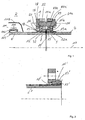
- FIG. 1 shows in the left part in longitudinal section a part of a flow meter 2, connected to a process pipe 4 via a flange connection 1 according to the invention is.
- the flow device, the piping and the flange connection are formed rotationally symmetrical, indicated by the center line 10, the same time Symmetry line is.
- the flowmeter is designed as a magnetic-inductive flowmeter. It comprises a measuring tube 6 to which the further subsystems are mounted. In the For reasons of clarity, not all of these subsystems are shown in FIG. 1, only the magnet system 90 with the exciting coil 91 and the ferromagnetic core 92, which together by means of conventional connecting elements 93 on the measuring tube are mounted wall, and the housing 94 are shown.
- the measuring tube 6 is made Made of metal, as usual in the art of stainless steel. It has an inner radius Ri, which is approximately constant over the entire tube length, and an outer diameter Ra. From the difference between the inner radius Ri and the outer radius Ra is the pipe wall thickness determined ..
- an extension region E At the end 8 of the measuring tube 6, in an extension region E, has the tube wall of the measuring tube 6 on a conical Anformung 12. It points radially outward, and has a sawtooth-shaped longitudinal contour with a first rising flat Flank 13 and a steeply sloping second edge 15.
- the pipe end 8 facing Steep flank 15 of Anformung 12 forms with the pipe end 8 together Sealing surface 14.
- the Anformung 12 was by winding a fiber composite material on the tail of the measuring tube 6 and then smoothing the flanks 13, 15, according to one of the prior art for the manufacture of components made of fiber composite material known methods that are not described here need to be.
- the effective pipe wall thickness t2 in the expansion area determined as the difference from the effective pipe outside diameter, that is the distance between the center line and the outer surface of the Anformung 12, and the tube inner diameter Ri, greater than the pipe wall thickness t1 outside the expansion area E.
- t2 grows, starting from a value t1 at the device-side beginning of the extension range E, continuously towards the tube end, the longitudinal section of the outer circumferential contour of the measuring tube in the extension region 12 a polynomial 1.
- the process tube 4 is a metal tube. Its nominal diameter is the nominal diameter adapted to the measuring tube 6. Also on the end piece 5 of the process tube 4th is a cone-shaped Anformung 12a with sawtooth-shaped longitudinal section contour, comprising a first, flat rising edge 13a and a second, towards the pipe end steeply sloping flank 15a, applied, also by winding fiber composite material and then smoothing the flanks.
- the first flank 13 In positive and non-positive contact with the Anformung 12 of the measuring tube 6 is present the first flank 13 an annular spacer 16 with its inner peripheral surface 18 at.
- the longitudinal section contour of the inner circumferential surface 18 of the intermediate piece 16, the longitudinal section contour of the first flank 13 of the Anformung 12 is adjusted.
- the outer peripheral surface 20 of the intermediate piece 16 has a step-shaped Longitudinal contour on.
- a flange 22 On the outer peripheral surface 20 of the intermediate piece 16 is in positive and non-positive Connect a flange 22 with its inner peripheral surface 24 at.
- the longitudinal sectional contour of the inner circumferential surface 24 of the flange 22 is the stepped longitudinal contour of the outer peripheral surface 20 of the intermediate piece 16 adapted.
- an intermediate piece 16a At the end piece 5 of the process tube 4 is an intermediate piece 16a in an analogous manner and a flange 22a attached.
- 22 a are in conventional Way bores for receiving the clamping screws 28 introduced.
- FIG. 1 shows only one such bore, indicated by its center line 26.
- the clamping screw 28 is screwed with a lock nut 29.
- a sealing ring 32 is attached, which facilitates the production of a fluid-tight pipe connection. If the sealing surfaces, formed by the pipe ends and the steep flanks 15, 15a of the projections 12, 12a are executed smooth enough, if necessary, can also be dispensed with the sealing ring 32 and yet a fluid tight tube connection can be made.
- the Anformung 12 on the measuring tube 6 is already at the beginning of the manufacturing process attached to the measuring tube end 8. Then in the usual way, all other subsystems attached to the measuring tube until the measuring device is ready. Only now will the Flange ring 22 pushed over. The inner diameter of the flange ring 22 is then naturally larger than the largest outer diameter of the measuring tube with attached Anformung 12.
- the intermediate piece 16 may for example consist of two half-shells, which are attached to the measuring tube end 8 from the sides and latched together be, in such a way that the annular spacer 16 with an inner diameter arises, which is larger than the measuring tube diameter, but smaller than the Diameter of the molding is.
- the Anformung 12a at the end of the process tube can already during production the process tube has been attached, or it is wound up in the installation position.
- the process tube side spacer 16a is formed in the same manner as the Both sides can be made of metal or again of fiber composite material consist. They are still loosely on the after their attachment first flanks 13, 13a of the two projections 12, 12a, but also already be mounted in a positive and / or non-positive connection.
- the flange was 22, 22 a is pushed onto the ends of the measuring tube 6 or process tube 4. They lay easy on and easy to move. Their shape, in particular outer diameter, Thickness as well as number and diameter of the holes, is customer-specific chosen and manufactured.
- both flange washers are in their mounting position brought so that their inner peripheral surfaces 24, 24 a form-fitting manner the outer peripheral surfaces 20, 20a of the intermediate pieces 16, 16 abut. Then the clamping screws 28 are inserted and both flange by means of this pressed against each other and so tightened with the lock nuts 29 that in opposite directions on the measuring tube 6 and the process tube 4 acting axial forces are exerted. The measuring tube end is thereby pressed against the end of the process tube and both become so strained that over the between the measuring tube end and the conduit end sealing surface 14 then the measuring tube 6 fluid-tight with the process tube. 4 connected is.
- Fig. 2 shows another embodiment of a flange according to the invention.
- the same, similar or equivalent components are given the same reference numerals as provided in Fig. 1, supplemented by a superscript apostrophe. It is only the portion of the flange connection located on the measuring tube 6 'is shown
- the process pipe located counterpart can be analogous to this or conventional executed by a welded flange or in the manner shown in Fig. 1 be.
- the embodiment of FIG. 2 differs from that of FIG. 1 in that the longitudinal section contour of the flat rising first edge 13 'of Anformung 12 'is formed hyperbola.
- the inner peripheral surface Adapted 18 'of the intermediate piece 16' of this hyperbolic longitudinal section contour so that both again during clamping - like the key to the lock - into each other fit and thus a positive and non-positive connection for transmitting the axial forces can be produced.
- the hyperbolic longitudinal contour has the advantage that the Power distribution can be optimally adjusted.
- FIG. 2 Another difference between Figs. 2 and 1 is that in the embodiment 2, the measuring tube 6 'with the Anformung 13' at the end of the measuring tube complete built in a manufacturing process of fiber composite material and, for example was produced in winding technology.
- the measuring tube 6 'with the Anformung 13' could also be a casting, and the Anformung 13 'when pouring directly be poured. Likewise, could also be instead a Hyperbelform another waveform for the longitudinal section contour of the Anformung 13 'are selected.
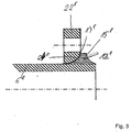
- FIG. 3 shows a third embodiment of a flange connection according to the invention.
- the same, similar or equivalent components are given the same reference numerals as provided in Fig. 1, supplemented by two superscript apostrophes.
- the formation is in the form of a bead 13 "formed with Tafelberg-like longitudinal section contour, wound on the tail of the measuring tube 6 "made of fiber composite material and provided with two flanks 13 "and 15", both a hyperbolic longitudinal cross-sectional contour exhibit.
- Fig. 1 shows a third embodiment of a flange connection according to the invention.
- the same, similar or equivalent components are given the same reference numerals as provided in Fig. 1, supplemented by two superscript apostrophes.
- the formation is in the form of a bead 13 "formed with Tafelberg-like longitudinal section contour, wound on the tail of the measuring tube 6 "made of fiber composite material and provided with two flanks 13 "and 15", both a hyperbolic longitudinal cross-sectional contour exhibit.
- the inner peripheral surface 24 "of the flange 22" formed so that their longitudinal sectional contour of those the hyperbolic longitudinal sectional contour of the rising flank 13 "of the bead 12" is adjusted so that both again when tightening - like the key to the lock - fit into each other and thus a positive and non-positive connection for transmission the axial forces can be produced.
- Fig. 3 thus shows a flange according to the invention without intermediate piece.
- the Flange plate must be pushed over the measuring tube in this embodiment before the bead 12 "is applied, either during production done or subsequently shortly before the installation of the meter in the process pipeline.
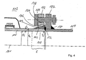
- Fig. 4 shows an embodiment of a flange according to the invention with a welded on the process pipe side in a conventional manner to the process pipe 104 Counter flange 182, leaving a weld 180 at the interface between the process tube 104 and the counter flange 182 is formed.
- the measuring tube side part of the flange connection is constructed exactly as described in Fig. 1. Same or equivalent components or assemblies wear otherwise in Fig. 4 the same Reference numerals as in Fig. 1, each increased by the value 100.
- Fig. 5 shows a further embodiment of the invention, with a conical widening of the measuring tube at the end of the measuring tube. Same, similar or equivalent components are provided with the same, but increased by 200 reference numerals as shown in Fig. 1. Only the part of the flange connection located on the measuring tube 206 is shown, the counterpart located on the process tube can be analogous to this or also conventionally by a welded flange or in the manner as in Fig. 1st be shown shown.
- the measuring tube 203 is widened in an extension region E at the measuring tube end 208, in such a way that, due to the widening, a tube end 208 of the measuring tube 206 points towards the tube end 208 rising edge 213 is formed.
- the pipe wall thickness t2 in the extension area E is unchanged here with respect to the pipe wall thickness t1 outside the expansion area E.
- the pipe inside diameter becomes larger towards the pipe end.
- the measuring tube 206 has an inner diameter R1, towards the end of the extension region E and thus of the measuring tube 206 is the inner tube diameter expanded to a value R2, where R2> R1.
- the longitudinal section of the outer circumferential contour of the measuring tube in the extension area E corresponds to a polynomial of the first degree, ie a straight line with a positive slope towards the end of the pipe. It is in the example of FIG. 5 is a conical expansion with a cone angle ⁇ shown.
- the measuring tube 206 with the extension region E is in the example of FIG. 5 from a Metal tube manufactured, for example in casting.
- the extension area E with the However, conical expansion could also in a conventional manner to the measuring tube 206 welded. It could also be the measuring tube 206 together with the Expansion in the extension area E completely in fiber composite technology, for example by winding, be prepared.
- FIG. 5 can also be considered in fluidic view Measuring tube with an inlet area - this corresponds to the extension area E - and a constricted measuring zone - this corresponds to the measuring tube area outside the expansion region E.
- the process tube by means of the invention Flange connection of Fig. 5 is connected to the measuring tube, has a Inner diameter of R2.
- the measuring zone thus has a smaller inner diameter as the process tube, therefore above the use of the term "constricted measuring zone".
- the measuring tube of a flow meter gets the flowing medium in the measuring tube due to the reduced Measuring tube cross section a higher flow velocity in the measuring tube than outside of the measuring tube in the process tube. If the meter is a magneto-inductive Flow meter is, so affects an increase in the flow velocity in the measuring tube positive on the measurement accuracy.
- a flange connection according to the invention according to the embodiment of FIG. 5 As a further advantage in addition to the simple design of the flange an increased Result in measurement accuracy.
- an angle ⁇ of 16 ° very low For flow reasons, for an embodiment of the invention shown in FIG. 5 an angle ⁇ of 16 ° very low. Other larger or smaller angles, for example 10 °, 12 °, 14 °, 18 °, 20 °, 30 ° would also be advantageous.
Landscapes
- Engineering & Computer Science (AREA)
- General Engineering & Computer Science (AREA)
- Mechanical Engineering (AREA)
- Flanged Joints, Insulating Joints, And Other Joints (AREA)
Applications Claiming Priority (2)
| Application Number | Priority Date | Filing Date | Title |
|---|---|---|---|
| DE10355848A DE10355848A1 (de) | 2003-11-26 | 2003-11-26 | Flanschverbindung und Verfahren zu deren Herstellung |
| DE10355848 | 2003-11-26 |
Publications (2)
| Publication Number | Publication Date |
|---|---|
| EP1536176A2 true EP1536176A2 (fr) | 2005-06-01 |
| EP1536176A3 EP1536176A3 (fr) | 2006-01-25 |
Family
ID=34442351
Family Applications (1)
| Application Number | Title | Priority Date | Filing Date |
|---|---|---|---|
| EP04025719A Withdrawn EP1536176A3 (fr) | 2003-11-26 | 2004-10-29 | Raccord à brides et son procédé de fabrication |
Country Status (6)
| Country | Link |
|---|---|
| US (1) | US20050146139A1 (fr) |
| EP (1) | EP1536176A3 (fr) |
| JP (1) | JP2005155919A (fr) |
| CN (1) | CN1621728A (fr) |
| CA (1) | CA2488433A1 (fr) |
| DE (1) | DE10355848A1 (fr) |
Cited By (2)
| Publication number | Priority date | Publication date | Assignee | Title |
|---|---|---|---|---|
| EP2522893A3 (fr) * | 2011-05-13 | 2013-02-06 | Veritas Ag | Agencement de tubes |
| EP2715202A2 (fr) * | 2011-05-30 | 2014-04-09 | Ensival-Moret France | Bride de raccordement d'une tuyauterie hydraulique ou pneumatique d'une machine industrielle |
Families Citing this family (15)
| Publication number | Priority date | Publication date | Assignee | Title |
|---|---|---|---|---|
| PL212621B1 (pl) * | 2009-04-30 | 2012-10-31 | Spyra Primo Poland Spolka Z Ograniczona Odpowiedzialnoscia | Rura sztywna |
| MX345431B (es) * | 2012-01-03 | 2017-01-31 | Micro Motion Inc | Método y aparato de retención de brida en un medidor de fluido. |
| WO2014129911A1 (fr) * | 2013-02-19 | 2014-08-28 | Fisher & Paykel Healthcare Limited | Appareil et procédé pour fournir des gaz à un utilisateur |
| NO337989B1 (no) * | 2014-04-08 | 2016-07-18 | Odin Connect As | Fremgangsmåte og konstruksjon for sammenkopling av rør |
| GB2532736A (en) * | 2014-11-25 | 2016-06-01 | Emstec Gmbh | An improved seawater suction system |
| GB2532735A (en) | 2014-11-25 | 2016-06-01 | Emstec Gmbh | Improvement in or relating to water suction hoses |
| CN109416141B (zh) * | 2016-07-20 | 2021-03-23 | 李相璇 | 能够防止扭曲的塑料阀 |
| US20180187819A1 (en) * | 2017-01-05 | 2018-07-05 | Salco Products, Inc. | Attachment flange assembly and method |
| TW201914724A (zh) * | 2017-09-22 | 2019-04-16 | 昆山新萊潔淨應用材料股份有限公司 | 腔體管件異質焊接結構 |
| GB2580692B (en) * | 2019-01-25 | 2022-09-28 | Danfoss Power Solutions Ii Technology As | Flange for a hose |
| RU2746030C1 (ru) * | 2020-02-27 | 2021-04-06 | Владимир Васильевич Шайдоров | Механическое соединение труб среднего диаметра |
| JP7288423B2 (ja) * | 2020-03-30 | 2023-06-07 | 積水化学工業株式会社 | 管継手 |
| CN112253863B (zh) * | 2020-10-29 | 2022-04-08 | 宝钛华神钛业有限公司 | 一种避免海绵钛氧化的单法兰机构 |
| CN117146078A (zh) * | 2023-07-05 | 2023-12-01 | 湖北大洋塑胶有限公司 | 复合管材 |
| CN117108833A (zh) * | 2023-10-09 | 2023-11-24 | 四川金元管业有限公司 | 一种连续纤维增强聚乙烯管的生产方法及连接方法 |
Family Cites Families (13)
| Publication number | Priority date | Publication date | Assignee | Title |
|---|---|---|---|---|
| US1542940A (en) * | 1923-03-05 | 1925-06-23 | Edward J Hughes | Flange joint |
| US2449265A (en) * | 1947-11-08 | 1948-09-14 | Glenn B Williams | Adjustable conduit for radiator and engine connection |
| US2880020A (en) * | 1955-10-12 | 1959-03-31 | Richard R Audette | Hose coupling with wedge hose gripping means |
| US3030253A (en) * | 1959-03-09 | 1962-04-17 | Resistoflex Corp | Method of assembling a flange to a laminated non-metallic pipe |
| US3977709A (en) * | 1975-05-08 | 1976-08-31 | Fischer & Porter Co. | Universal interface gasket |
| DE2530370C2 (de) * | 1975-07-08 | 1983-11-24 | Rheinische Braunkohlenwerke AG, 5000 Köln | Unter Verwendung von Kupplungsgliedern zu einer zugfesten Rohrleitung zusammensetzbare Asbestzementrohre |
| FR2349782A1 (fr) * | 1976-04-26 | 1977-11-25 | Clement Louis | Raccord pour les tubes utilises notamment dans le domaine du chauffage ou dans le domaine du transport de fluides tels que l'air comprime, les gaz, les hydrocarbures et autres |
| CH643341A5 (de) * | 1980-04-09 | 1984-05-30 | Fischer Ag Georg | Flanschverbindung. |
| FR2538074A1 (fr) * | 1982-12-20 | 1984-06-22 | Plastiques Agricoles Ste Medit | Procede et raccords pour connecter un tube en matiere plastique sur une piece a bride |
| US4773306A (en) * | 1986-07-08 | 1988-09-27 | Pneumo Abex Coporation | Dual tandem composite cylinder assembly including separately formed cylinder barrels |
| DE3833535C2 (de) * | 1988-10-01 | 2001-02-01 | Werner Roehrs Gmbh & Co Kg Dr | Rohrkupplung |
| US5971001A (en) * | 1997-05-29 | 1999-10-26 | Dresser Industries, Inc. | Fitting assembly and method for tapping into a conduit |
| DE10024738A1 (de) * | 2000-05-19 | 2001-11-29 | Qvf Engineering Gmbh | Glasbauteile mit einer ableitfähigen Beschichtung, ihre Verwendung und daraus hergestellte Apparate, Anlagen und Rohrleitungen |
-
2003
- 2003-11-26 DE DE10355848A patent/DE10355848A1/de not_active Ceased
-
2004
- 2004-10-29 EP EP04025719A patent/EP1536176A3/fr not_active Withdrawn
- 2004-11-25 JP JP2004341145A patent/JP2005155919A/ja active Pending
- 2004-11-25 CA CA002488433A patent/CA2488433A1/fr not_active Abandoned
- 2004-11-25 CN CNA2004100917958A patent/CN1621728A/zh active Pending
- 2004-11-26 US US10/996,386 patent/US20050146139A1/en not_active Abandoned
Cited By (2)
| Publication number | Priority date | Publication date | Assignee | Title |
|---|---|---|---|---|
| EP2522893A3 (fr) * | 2011-05-13 | 2013-02-06 | Veritas Ag | Agencement de tubes |
| EP2715202A2 (fr) * | 2011-05-30 | 2014-04-09 | Ensival-Moret France | Bride de raccordement d'une tuyauterie hydraulique ou pneumatique d'une machine industrielle |
Also Published As
| Publication number | Publication date |
|---|---|
| CA2488433A1 (fr) | 2005-05-26 |
| JP2005155919A (ja) | 2005-06-16 |
| CN1621728A (zh) | 2005-06-01 |
| US20050146139A1 (en) | 2005-07-07 |
| EP1536176A3 (fr) | 2006-01-25 |
| DE10355848A1 (de) | 2005-07-21 |
Similar Documents
| Publication | Publication Date | Title |
|---|---|---|
| EP1536176A2 (fr) | Raccord à brides et son procédé de fabrication | |
| EP0439749B1 (fr) | Raccord vissé | |
| EP3314214B1 (fr) | Débitmètre comprenant un canal de mesure et des canaux auxiliaires | |
| DE3720620A1 (de) | Verfahren zur herstellung von rohrverbindungen fuer hochdruckhydraulikleitungen | |
| DE60017902T2 (de) | Fluidzuleitung zur Herabsetzung der Druckschwankungen | |
| EP0394632A1 (fr) | Palpeur de pression et procédé pour sa fabrication | |
| DE2129900C3 (de) | Fitting | |
| DE3443943A1 (de) | Rohrverbindung | |
| EP1151251B1 (fr) | Debitmetre electromagnetique et procede permettant de le produire | |
| EP0527140B1 (fr) | Assemblage par liaison de forme d'une electrovanne avec un bloc-carter, ainsi que procede pour sa realisation | |
| DE8524633U1 (de) | Luftfeder mit pneumatischen Anschluß | |
| DE4028237C2 (fr) | ||
| DE19503346C2 (de) | Rohrbauteil | |
| DE2221674A1 (de) | Schlauchkupplung | |
| DE2330593A1 (de) | Keramik-stroemungsmesswertumformer | |
| EP1953441A2 (fr) | Conduite dotée d'une pièce de raccordement | |
| DE3719585A1 (de) | Loesbare sowie nichtloesbare dichte verbindung zweier benachbarter rohrleitungen | |
| DE60216087T2 (de) | Vorrichtung zum durchführen einer leitung oder dergleichen durch ein bauelement | |
| EP2226545A2 (fr) | Elément de conduite et utilisation correspondante | |
| DE60221513T2 (de) | Verfahren zur herstellung eines mit flansch versehenen elements und ein mit flansch versehenes element | |
| WO1996035526A1 (fr) | Procede et outils de compression servant a relier des elements tubulaires | |
| DE19757946C2 (de) | Rohrverbindung | |
| EP1662236B1 (fr) | Débitmètre massique Coriolis et methode pour fabriquer un tube de mesure pour un debitmètre massique Coriolis | |
| DE2251082A1 (de) | Zugfeste verriegelung von kanalisationselementen | |
| EP0950846B1 (fr) | Système de tuyauterie |
Legal Events
| Date | Code | Title | Description |
|---|---|---|---|
| PUAI | Public reference made under article 153(3) epc to a published international application that has entered the european phase |
Free format text: ORIGINAL CODE: 0009012 |
|
| AK | Designated contracting states |
Kind code of ref document: A2 Designated state(s): AT BE BG CH CY CZ DE DK EE ES FI FR GB GR HU IE IT LI LU MC NL PL PT RO SE SI SK TR |
|
| AX | Request for extension of the european patent |
Extension state: AL HR LT LV MK |
|
| PUAL | Search report despatched |
Free format text: ORIGINAL CODE: 0009013 |
|
| AK | Designated contracting states |
Kind code of ref document: A3 Designated state(s): AT BE BG CH CY CZ DE DK EE ES FI FR GB GR HU IE IT LI LU MC NL PL PT RO SE SI SK TR |
|
| AX | Request for extension of the european patent |
Extension state: AL HR LT LV MK |
|
| 17P | Request for examination filed |
Effective date: 20060711 |
|
| AKX | Designation fees paid |
Designated state(s): AT BE BG CH CY CZ DE DK EE ES FI FR GB GR HU IE IT LI LU MC NL PL PT RO SE SI SK TR |
|
| 17Q | First examination report despatched |
Effective date: 20060911 |
|
| STAA | Information on the status of an ep patent application or granted ep patent |
Free format text: STATUS: THE APPLICATION IS DEEMED TO BE WITHDRAWN |
|
| 18D | Application deemed to be withdrawn |
Effective date: 20080916 |