EP1536190A1 - Système de refroidissement avec circulation de réfrigérant liquide par pression - Google Patents
Système de refroidissement avec circulation de réfrigérant liquide par pression Download PDFInfo
- Publication number
- EP1536190A1 EP1536190A1 EP04025510A EP04025510A EP1536190A1 EP 1536190 A1 EP1536190 A1 EP 1536190A1 EP 04025510 A EP04025510 A EP 04025510A EP 04025510 A EP04025510 A EP 04025510A EP 1536190 A1 EP1536190 A1 EP 1536190A1
- Authority
- EP
- European Patent Office
- Prior art keywords
- refrigerant
- pumping
- refrigeration system
- pressure
- heat exchanger
- Prior art date
- Legal status (The legal status is an assumption and is not a legal conclusion. Google has not performed a legal analysis and makes no representation as to the accuracy of the status listed.)
- Withdrawn
Links
Images

Classifications
-
- F—MECHANICAL ENGINEERING; LIGHTING; HEATING; WEAPONS; BLASTING
- F25—REFRIGERATION OR COOLING; COMBINED HEATING AND REFRIGERATION SYSTEMS; HEAT PUMP SYSTEMS; MANUFACTURE OR STORAGE OF ICE; LIQUEFACTION SOLIDIFICATION OF GASES
- F25B—REFRIGERATION MACHINES, PLANTS OR SYSTEMS; COMBINED HEATING AND REFRIGERATION SYSTEMS; HEAT PUMP SYSTEMS
- F25B25/00—Machines, plants or systems, using a combination of modes of operation covered by two or more of the groups F25B1/00 - F25B23/00
- F25B25/005—Machines, plants or systems, using a combination of modes of operation covered by two or more of the groups F25B1/00 - F25B23/00 using primary and secondary systems
-
- F—MECHANICAL ENGINEERING; LIGHTING; HEATING; WEAPONS; BLASTING
- F25—REFRIGERATION OR COOLING; COMBINED HEATING AND REFRIGERATION SYSTEMS; HEAT PUMP SYSTEMS; MANUFACTURE OR STORAGE OF ICE; LIQUEFACTION SOLIDIFICATION OF GASES
- F25B—REFRIGERATION MACHINES, PLANTS OR SYSTEMS; COMBINED HEATING AND REFRIGERATION SYSTEMS; HEAT PUMP SYSTEMS
- F25B2400/00—Component parts or details not otherwise provided for in this subclass
- F25B2400/16—Receivers
- F25B2400/161—Receivers arranged in parallel
Definitions
- the invention relates to a cascade refrigerating system comprising a first high temperature refrigeration system operating with a first refrigerant, which high temperature refrigeration system comprises compressor means, connected to condensing means, where the first high temperature system further comprises heat exchanging means, where heat is exchanged from a second low temperature refrigeration system, which second low temperature refrigeration system comprises pumping means arranged to supply refrigerant to evaporating means.
- GB 1,146,428 describes improvements in a flooded coil refrigerant system where tanks are designed for collecting a recirculating excess refrigerant from the evaporators to eliminate slugging of the compressor.
- the driving force of the prior art system is the pressure difference between the compressor discharge or condenser pressure and the suction pressure of the compressor, similar to most other refrigerant systems.
- one of the receivers are connected to the condenser, and liquid refrigerant is filling the first receiver, which at the same time is connected through restriction means to flooded evaporators, from which refrigerant is led to the second receiver, where liquid is remaining and gas is led to the suction side of the compressor.
- valves are opened and closed in order to change the operation of the receivers.
- DE 3511421 A1 describes a refrigeration circuit, which comprises adjustable means for increasing the pressure in the refrigeration circuit with a low condensation temperature. In this way, it is possible to fulfil condensation by using very low refrigerant temperatures with a very low condensation pressure without circulation problems occurring.
- This system relates to energy savings using low condensing temperatures and thus maintaining sufficient refrigerant pressure for the expansion valve.
- EP 1 046 868 A2 describes a refrigeration system having a refrigeration cycle, which provides optimised energy consumption.
- This system also relates to energy savings using low condensing temperatures and thus maintaining sufficient refrigerant pressure for the expansion valve.
- GB 1,146,428 describes a liquid refrigerant recirculating system and relates to refrigerating systems and more particularly to improvements in systems in which the evaporator coils are supplied with an excess of liquid refrigerant, which excess is collected and re-circulated back through the evaporator.
- This invention relates to improvements in a flooded coil refrigerant system where tanks are designed for collecting a re-circulating excess refrigerant from the evaporators to eliminate slugging of the compressor.
- the invention relates to a refrigerating system where a liquid refrigerant is circulated in piping by means of pressure.
- the pressure is produced by using free or "low value" energy only without using any energy consuming pumps, compressor etc.
- the system includes an expansion device (i.e. expansion valve, orifice, capillary tube or similar) and an evaporator where the pressurized gas is produced by evaporating refrigerant.
- the pressurized gas is supplied into at least two receivers through each the pipe branch is provided with respective check valves and solenoid valves.
- the receivers are arranged to supply refrigerant to at least one evaporator through a check valve associated with each receiver.
- None of the prior art systems relates to the purpose of this invention, using free or "low value" energy for circulation of liquid refrigerant with pressure.
- the purpose of the invention is to provide an energy efficient refrigerating system that is suitable for refrigerant circulation with reduced energy consumption for circulation of refrigerant in refrigeration systems.
- the second low temperature refrigeration system comprises at least two pumping vessels connected through respective check valves, which pumping vessels are connected to heating means, in which refrigerant is evaporated for generating a higher pressure, which high pressure is lead to the top of the pumping vessels for pressing refrigerant with high pressure towards the evaporation means.
- the circulation system can operate with refrigerant completely without oil since the system does not include any compressors or pumps. This leads to better performance and better heat transfer.
- the heating means can be heated by any low temperature waste energy. Low value energy sources as air, water, and waste heat can be used for heating the heating means. The supplied energy must be removed by the first high temperature refrigeration system so these systems are not energy neutral.
- the heating means might be formed as at least one heat exchanger, which heat exchanger can be heated by the first refrigerant, which heat exchanger has an inlet connected to the outlet of the condensing means through control valves, and where the outlet from the heat exchanger is connected to the inlet of the heat exchanging means through pressure reduction means. It is hereby achieved the first refrigerant is used for the heating.
- the temperature of the refrigerant is reduced in the condensing means and has been mostly liquefied in the condensing means. By passing the heat exchanger, the mostly liquefied refrigerant is sub cooled, and the content of cooling energy is increased. The energy for evaporating the liquid is removed from the high stage of the cascade system making this application energy neutral.
- the heat exchanger has an inlet for the second refrigerant connected to the lower part of the pumping vessels, where the heat exchanger has an outlet connected to the upper part of the pumping vessels. It is hereby achieved that refrigerant liquid is supplied by gravity from one of two pumping vessels to a related heat exchanger located in the same level as the lower part of the pumping vessels.
- the second refrigerant is supplied by gravity in mostly liquid form from at least one of the pumping vessels through an outlet to a related heat exchanger, which heat exchanger is located at the same level as the lower part of the pumping vessel. It is hereby achieved that the refrigerant is injected into one or more heat exchangers where the pressurized gas is produced by evaporating the second refrigerant. In this way, a pressure difference is provided with enough force to press refrigerant through the refrigeration system.
- the pressurized gas produced by the evaporating refrigerant is supplied through solenoid valves into the vessel acting as high pressure. This makes the contained liquid refrigerant flow through non-return valves into the liquid line. In the meantime, a solenoid valve equalizes the pressure between the condenser and the other vessel, which makes the refrigerant fill the vessel by gravity.
- a control circuit makes the sequence alter so the second vessel is supplying liquid, and the first vessel is filling.
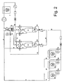
- Fig. 1 shows a cascade refrigerating system, where the cascade heat exchanger 2 is cooled by a high temperature (HT) refrigeration system 4.
- the HT refrigeration system 4 can be any suitable system using any suitable refrigerant.
- the heat exchanger 2 functions as the cascade condenser of the low temperature (LT) refrigeration system.
- Liquid flows through the pipe 6 and alternating further through the pipe 8 or 10, which leads to no-return valves 12 or 14 and through the pipe 16 or 18 into the pumping vessels 20 or 22.
- the outlet of the pumping vessels 20 or 22 are connected through pipe 24 or 26, through no-return valves 28 or 30 into the liquid line 32 which leads to flow restriction means 34,36,38 which restriction means might be electronically controlled expansion valves.
- the refrigerant is led further to evaporators 40,42,44.
- the outlet pipes 46,48,50 from the evaporators 40,42,44 are led through the common return line 52 to the cascade condenser 2.
- a part stream of the refrigerant is led from the pumping vessels 20 or 22 through the pipe 60 or 62 into the heat exchangers 64 or 66 where liquid refrigerant is evaporated when exposed to a heat source.
- the gas is led back to the related vessels 20,22 through the pipes 68,70, generating pressure for the operation of the system.
- the vessel 20,22 will in loading mode equalize pressure through pipe 72,74, onto the solenoid valves 76,78, through the pipes 80,82,84 into the common return line 52.
- the HT refrigeration system 4 is used as the heat source, where the liquid refrigerant is led through the liquid line 100, through the solenoid valves 102,104, into the heat exchangers 64,66 in operation.
- the sub-cooled HT liquid refrigerant is led through the pipes 106, 108, 110 into the HT expansion device 112.
- Operation mode A The vessel 20 is empty and loading, and the vessel 22 is full and supplying.
- the solenoid valve 102 is closed and the solenoid valve 76 is open equalizing the pressure between the vessel 20 and cascade condenser 2. Liquid refrigerant is led from the cascade condenser 2, through the pipe 6,8, non-return valve 12, and pipe 16, loading the vessel 20.
- the pressure is higher in the pipe 32 than in the pipe 24, so the non-return valve 28 is closed.
- Liquid refrigerant liquid is supplied by gravity from the vessel 22 to the heat exchanger 66 located at the same level as the lower part of the vessel 22.
- the liquid refrigerant When the liquid refrigerant is exposed to the heat source in the heat exchanger 66, the liquid evaporates and generates higher pressure in the vessel 22.
- the non-return valve 30 opens supplying liquid refrigerant into the liquid line 32.
- the vessel 22 is empty which could be detected by detection means or by using a timer (not shown).
- the detection or the timer means might communicate to an electronic system (also not shown), and when the vessel 22 is empty, the vessel 20 is probably more or less full of a liquid. In this situation, the system alternates into operation mode B.
- Operation mode B The vessel 22 is empty and loading, and the vessel 20 is full and supplying.
- the solenoid valve 104 is closed, and the solenoid valve 78 is open equalizing the pressure between the vessel 22 and the cascade condenser 2. Liquid refrigerant is led from the cascade condenser 2 through the pipe 6, 10, the non-return valve 14, and the pipe 18 loading the vessel 22.
- the pressure is higher in the pipe 32 is higher than in the pipe 26 so the non-return valve 30 is closed.
- Liquid refrigerant liquid is supplied by gravity from the vessel 20 to the heat exchanger 64 located at the same level as the lower part of the vessel 20.
- the non-return valve 28 opens supplying liquid refrigerant into the liquid line 32.
- the vessel 20 is empty which could be detected by detection means or by using a timer (not shown).
- the detection or the timer means might communicate with an electronic system (also not shown), and when the vessel 20 is empty, the vessel 22 is probably more or less full of a liquid. In this situation, the system alternates back into operation mode A.
- the system can operate by changing between an active (supplying) and an inactive (loading) vessel during the whole operation.
- Fig. 2 shows an alternative embodiment of the invention where only the heat exchangers 64,66 are changed in the fig. 2. Because of these very few changes, the description is the same for both fig. 1 and fig. 2. The only difference between the two figures is that the heat exchangers on fig. 2 are placed as separate components outside the pumping vessels 20,22 where the heat exchangers in fig. 2 are integrated into the pumping vessels 20,22.
Landscapes
- Engineering & Computer Science (AREA)
- Physics & Mathematics (AREA)
- Mechanical Engineering (AREA)
- Thermal Sciences (AREA)
- General Engineering & Computer Science (AREA)
- Devices That Are Associated With Refrigeration Equipment (AREA)
Priority Applications (1)
| Application Number | Priority Date | Filing Date | Title |
|---|---|---|---|
| EP04025510A EP1536190A1 (fr) | 2003-11-28 | 2004-10-27 | Système de refroidissement avec circulation de réfrigérant liquide par pression |
Applications Claiming Priority (3)
| Application Number | Priority Date | Filing Date | Title |
|---|---|---|---|
| EP03027254 | 2003-11-28 | ||
| EP03027254A EP1536192A1 (fr) | 2003-11-28 | 2003-11-28 | Système frigorifique |
| EP04025510A EP1536190A1 (fr) | 2003-11-28 | 2004-10-27 | Système de refroidissement avec circulation de réfrigérant liquide par pression |
Publications (1)
| Publication Number | Publication Date |
|---|---|
| EP1536190A1 true EP1536190A1 (fr) | 2005-06-01 |
Family
ID=34466332
Family Applications (1)
| Application Number | Title | Priority Date | Filing Date |
|---|---|---|---|
| EP04025510A Withdrawn EP1536190A1 (fr) | 2003-11-28 | 2004-10-27 | Système de refroidissement avec circulation de réfrigérant liquide par pression |
Country Status (1)
| Country | Link |
|---|---|
| EP (1) | EP1536190A1 (fr) |
Cited By (3)
| Publication number | Priority date | Publication date | Assignee | Title |
|---|---|---|---|---|
| EP1816415A2 (fr) | 2006-02-07 | 2007-08-08 | Birton A/S | Système de refroidissement avec circulation de réfrigérant liquide par pression |
| EP2333458A1 (fr) * | 2009-12-03 | 2011-06-15 | Samsung Electronics Co., Ltd. | Circuit hydraulique et appareil de cycle de réfrigération l'utilisant |
| JP2016017697A (ja) * | 2014-07-08 | 2016-02-01 | 株式会社前川製作所 | アイスリンクの冷却設備及び冷却方法 |
Citations (4)
| Publication number | Priority date | Publication date | Assignee | Title |
|---|---|---|---|---|
| EP0857936A1 (fr) * | 1995-10-24 | 1998-08-12 | Daikin Industries, Limited | Systeme de transport de chaleur |
| JPH1123079A (ja) * | 1997-06-27 | 1999-01-26 | Mitsubishi Heavy Ind Ltd | 冷凍装置 |
| JPH11132507A (ja) * | 1997-10-29 | 1999-05-21 | Daikin Ind Ltd | 冷凍装置 |
| JP2002048422A (ja) * | 2000-07-31 | 2002-02-15 | Kyoritsu Reinetsu Kk | ヒートポンプ |
-
2004
- 2004-10-27 EP EP04025510A patent/EP1536190A1/fr not_active Withdrawn
Patent Citations (4)
| Publication number | Priority date | Publication date | Assignee | Title |
|---|---|---|---|---|
| EP0857936A1 (fr) * | 1995-10-24 | 1998-08-12 | Daikin Industries, Limited | Systeme de transport de chaleur |
| JPH1123079A (ja) * | 1997-06-27 | 1999-01-26 | Mitsubishi Heavy Ind Ltd | 冷凍装置 |
| JPH11132507A (ja) * | 1997-10-29 | 1999-05-21 | Daikin Ind Ltd | 冷凍装置 |
| JP2002048422A (ja) * | 2000-07-31 | 2002-02-15 | Kyoritsu Reinetsu Kk | ヒートポンプ |
Non-Patent Citations (3)
| Title |
|---|
| PATENT ABSTRACTS OF JAPAN vol. 1999, no. 04 30 April 1999 (1999-04-30) * |
| PATENT ABSTRACTS OF JAPAN vol. 1999, no. 10 31 August 1999 (1999-08-31) * |
| PATENT ABSTRACTS OF JAPAN vol. 2002, no. 06 4 June 2002 (2002-06-04) * |
Cited By (4)
| Publication number | Priority date | Publication date | Assignee | Title |
|---|---|---|---|---|
| EP1816415A2 (fr) | 2006-02-07 | 2007-08-08 | Birton A/S | Système de refroidissement avec circulation de réfrigérant liquide par pression |
| EP1816415A3 (fr) * | 2006-02-07 | 2010-11-24 | Birton A/S | Système de refroidissement avec circulation de réfrigérant liquide par pression |
| EP2333458A1 (fr) * | 2009-12-03 | 2011-06-15 | Samsung Electronics Co., Ltd. | Circuit hydraulique et appareil de cycle de réfrigération l'utilisant |
| JP2016017697A (ja) * | 2014-07-08 | 2016-02-01 | 株式会社前川製作所 | アイスリンクの冷却設備及び冷却方法 |
Similar Documents
| Publication | Publication Date | Title |
|---|---|---|
| CN102109239B (zh) | 制冷装置 | |
| JP3743861B2 (ja) | 冷凍空調装置 | |
| CN102326035A (zh) | 热泵系统 | |
| EP2959239B1 (fr) | Gestion de lubrifiant dans un système de chauffage, de ventilation, et de climatisation | |
| EP1662212A2 (fr) | Conditionneur d'air et procédé de commande de celui-ci | |
| JP3637786B2 (ja) | ブライン冷却装置 | |
| CN102109241B (zh) | 制冷装置 | |
| CN102109240A (zh) | 制冷装置 | |
| KR101190317B1 (ko) | 냉동장치 | |
| KR20110097367A (ko) | 칠러 | |
| JP2009257684A (ja) | 圧縮式冷凍機及びその潤滑油回収方法 | |
| CN102109260A (zh) | 制冷装置 | |
| EP1816415A2 (fr) | Système de refroidissement avec circulation de réfrigérant liquide par pression | |
| US7721559B2 (en) | Multi-type air conditioner and method for controlling the same | |
| KR20220073416A (ko) | 하이브리드 멀티 공조 시스템 및 그의 제어 방법 | |
| US20090223232A1 (en) | Defrost system | |
| JP5543093B2 (ja) | 圧縮式冷凍機、及びその運転方法 | |
| FI92432B (fi) | Kompressiojäähdytysjärjestelmä öljynerottimella | |
| KR200267362Y1 (ko) | 냉동시스템 | |
| KR100378531B1 (ko) | 터보냉동기의 냉매와 오일 분리/회수장치 | |
| KR101509575B1 (ko) | 오일분배장치 및 이를 포함하는 공기 조화기 | |
| EP1616136B1 (fr) | Systeme de refrigeration et son mode de fonctionnement | |
| RU2000108131A (ru) | Способ работы холодильной установки с аккумуляцией холода и система для его осуществления | |
| KR102901010B1 (ko) | 냉동싸이클 시스템의 수액기 온도를 낮추기 위한 냉매순환장치 및 냉매순환방법 | |
| EP1536192A1 (fr) | Système frigorifique |
Legal Events
| Date | Code | Title | Description |
|---|---|---|---|
| PUAI | Public reference made under article 153(3) epc to a published international application that has entered the european phase |
Free format text: ORIGINAL CODE: 0009012 |
|
| AK | Designated contracting states |
Kind code of ref document: A1 Designated state(s): AT BE BG CH CY CZ DE DK EE ES FI FR GB GR HU IE IT LI LU MC NL PL PT RO SE SI SK TR |
|
| AX | Request for extension of the european patent |
Extension state: AL HR LT LV MK |
|
| RAP1 | Party data changed (applicant data changed or rights of an application transferred) |
Owner name: BIRTON A/S |
|
| 17P | Request for examination filed |
Effective date: 20051130 |
|
| AKX | Designation fees paid |
Designated state(s): AT BE BG CH CY CZ DE DK EE ES FI FR GB GR HU IE IT LI LU MC NL PL PT RO SE SI SK TR |
|
| RAP1 | Party data changed (applicant data changed or rights of an application transferred) |
Owner name: CARRIER REFRIGERATION DENMARK A/S |
|
| RAP1 | Party data changed (applicant data changed or rights of an application transferred) |
Owner name: CARRIER CORPORATION |
|
| 17Q | First examination report despatched |
Effective date: 20111130 |
|
| STAA | Information on the status of an ep patent application or granted ep patent |
Free format text: STATUS: THE APPLICATION IS DEEMED TO BE WITHDRAWN |
|
| 18D | Application deemed to be withdrawn |
Effective date: 20120411 |