EP1536210A2 - Procédé de fonctionnement d'un appareil de mesure - Google Patents
Procédé de fonctionnement d'un appareil de mesure Download PDFInfo
- Publication number
- EP1536210A2 EP1536210A2 EP04024764A EP04024764A EP1536210A2 EP 1536210 A2 EP1536210 A2 EP 1536210A2 EP 04024764 A EP04024764 A EP 04024764A EP 04024764 A EP04024764 A EP 04024764A EP 1536210 A2 EP1536210 A2 EP 1536210A2
- Authority
- EP
- European Patent Office
- Prior art keywords
- measuring operation
- normal
- diagnostic
- normal measuring
- interruption
- Prior art date
- Legal status (The legal status is an assumption and is not a legal conclusion. Google has not performed a legal analysis and makes no representation as to the accuracy of the status listed.)
- Ceased
Links
Images

Classifications
-
- G—PHYSICS
- G01—MEASURING; TESTING
- G01F—MEASURING VOLUME, VOLUME FLOW, MASS FLOW OR LIQUID LEVEL; METERING BY VOLUME
- G01F1/00—Measuring the volume flow or mass flow of fluid or fluent solid material wherein the fluid passes through a meter in a continuous flow
- G01F1/56—Measuring the volume flow or mass flow of fluid or fluent solid material wherein the fluid passes through a meter in a continuous flow by using electric or magnetic effects
- G01F1/58—Measuring the volume flow or mass flow of fluid or fluent solid material wherein the fluid passes through a meter in a continuous flow by using electric or magnetic effects by electromagnetic flowmeters
-
- G—PHYSICS
- G01—MEASURING; TESTING
- G01D—MEASURING NOT SPECIALLY ADAPTED FOR A SPECIFIC VARIABLE; ARRANGEMENTS FOR MEASURING TWO OR MORE VARIABLES NOT COVERED IN A SINGLE OTHER SUBCLASS; TARIFF METERING APPARATUS; MEASURING OR TESTING NOT OTHERWISE PROVIDED FOR
- G01D18/00—Testing or calibrating apparatus or arrangements provided for in groups G01D1/00 - G01D15/00
Definitions
- the invention relates to a method for operating a measuring device, wherein the meter is provided with a plurality of diagnostic functions.
- diagnostic functions should be used to check the operation of the measuring instruments in order to: to improve their reliability.
- diagnostic functions are known, which have no influence on the measuring operation, and on the other hand those that interfere with normal measuring operation, ie only when switched off Measuring operation can be performed.
- the previously derived and indicated object is achieved by that such a sequence control for performing the diagnostic functions takes place that the normal measuring operation of the meter is interrupted while the interruption of the normal measuring operation, a first diagnostic function is performed, the normal measuring operation after performing the first Diagnostic function is resumed, the normal measuring operation of the Meter is interrupted again and during the interruption of the normal measuring operation, a second diagnostic function is performed.
- Essential to the invention is therefore that the operation of the meter for performing of diagnostic functions is subjected to a flow control, namely such that the normal measuring operation is interrupted and in these interruptions consecutively different diagnostic functions be performed.
- Sequence control can be ensured that different Diagnostic functions do not interfere or affect one another and that too the normal measuring operation by the diagnostic functions not to a greater extent is impaired.
- the various diagnostic functions can so be repeated after different times, so that in total basically any number of diagnostic functions in the invention Flow control can be integrated.
- the repetition of diagnostic functions is basically arbitrary namely in particular not be periodic. However, one is periodic Repeated execution of the diagnostic function provided, so In principle all diagnostic functions can be repeated with the same frequency become. However, according to a preferred embodiment of the invention provided that the individual diagnostic functions with different Frequencies are repeated periodically. This way can be special important diagnostic functions are repeated more often. It can on the one hand be provided that the repetition frequency for the diagnostic functions preset is. On the other hand, the refresh rate for the diagnostic functions but also be adjustable by the user of the meter.
- the respective duration of the interruption of the normal Measuring mode for all diagnostic functions is controlled.
- the interruptions of the normal measuring operation must therefore not for all diagnostic functions be the same length, so that z. B. very quickly performed diagnostic functions also only with a very short interruption of the normal measuring operation accompanied.
- the respective duration of the interruption of the normal Measuring operation is controlled in the range of 10 to 200 ms.
- the time interval between two interruptions of the normal measuring operation is controlled in the range of 1 to 100 s.
- the interruption of the normal measuring operation can basically be provided that no measured value is output. According to a preferred Development of the invention, however, is provided that during a Interruption of the normal measuring operation as measured value of the last determined Measured value is output. Alternatively, according to a preferred embodiment the invention provided that during an interruption of normal Meß ceremoniess a Hilfsmeß prepare takes place in the context of a Measured value with lower accuracy is determined and output.
- the invention provided that the initiation of a Hilfsmeß ists during an interruption of the normal measuring operation in dependence on the type of diagnostic function is controlled.
- This embodiment of the method takes into account that some diagnostic functions due to their Interaction with equipment of the meter any kind of measuring operation and thus exclude an auxiliary measuring operation. But with it not entirely on an auxiliary measuring operation during the interruptions of the having to forego normal measuring operation, in such diagnostic functions, which basically allow a measuring operation, individually a Hilfsmeß compassion started.
- the results of the individual diagnostic functions ie the ones determined Values can be output directly.
- the invention provides that the results of the individual Diagnostic functions are averaged over time. In this way are only short Interruptions of the normal measuring operation required, and it will be the Reliability of the determined diagnostic values increased. In doing so, diagnostic functions, which require multiple averagings, are repeated more often than other.
- the entire sequence control repeats periodically becomes.
- the entire process control ie all diagnostic functions, be deactivated, which can also be provided that only individual Diagnostic functions are disabled. This can on the one hand by the user itself, typically directly at the meter, or via a control input done electronically by a control system.
- Magnetic-inductive flowmeters are well known in the art and typically are a flowed through by a flowing medium measuring tube, two along a running at least substantially perpendicular to Meßrohrachse Connecting line arranged measuring electrodes and that at least in essentially perpendicular to the measuring tube axis and perpendicular to the connecting line the measuring electrodes extending magnetic field generating magnetic coils.
- a voltage is compared with one or both measuring electrodes a reference potential.
- the principle of the magnetic-inductive flow measurement is based on of electrodynamic induction: According to Faraday's law of induction arises in a flowing medium that carries charge carriers with it and passing through a magnetic field, an electric field strength perpendicular to Flow direction and perpendicular to the magnetic field. Within the magnetic field each one moves through the magnetic field and delivers a certain number Volume element of the flowing medium having charge carriers contributing to the field strength arising in this volume element a tapped over the measuring electrodes measuring voltage.
- a magnetic-inductive flowmeter can now as Diagnostic functions which, as described above, an inventive Sequential control are subjected to, inter alia, the following functions be provided: an electrode impedance measurement by a test current the electrodes of the magnetic inductive flowmeter, a linearity test by deliberately changing the field current, an addition of a known Test signal to the normal electrode signal to control the Pre-amplification and / or A / D conversion and the generation of an inhomogeneous Magnetic field. It should be noted that the generation of an inhomogeneous Magnetic field z. B. by opposing, in opposite directions current-carrying magnetic coils can be achieved.
- the sequence control for a magneto-inductive Flow meter can with respect to the timing provided in particular according to a preferred embodiment of the invention be that the time interval between two interruptions of the normal Controlled measuring operation of the magnetic inductive flowmeter so is that the time interval is a multiple of half the period corresponds to the magnetic field.
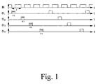
- Fig. 1 the control of the normal measuring operation M and on the other hand, the control of four different diagnostic functions D 1 , D 2 , D 3 and D 4 is shown schematically on the one hand.
- the normal measuring operation is interrupted regularly, wherein in the interruptions of the normal measuring operation successively the individual diagnostic functions are performed.
- the diagnostic functions are all repeated at the same frequency and that the respective interruption of the normal measuring operation for the individual diagnostic functions is always the same length.
- this is not absolutely necessary, but on the one hand, the repetition frequencies for the individual diagnostic functions and on the other hand, the respective durations of the interruptions of the normal measuring operation for the individual diagnostic functions may be different, namely adapted to the respective needs.
- the regular interruption of the normal measuring operation corresponds to the regular repetition, namely resumption of the normal measuring operation with a predetermined frequency f.
- the period T for the normal measuring operation is in the range between 1 and 100 s, while the duration ⁇ t for interrupting the normal measuring operation for performing a diagnostic function is only in the range of 10 to 200 ms lies.
- the ratios shown in FIG. 1 thus do not correspond to the actual chosen ratios of the durations.
- FIG. 2 shows diagrammatically a magnetic-inductive flowmeter. that with a flow control according to a preferred embodiment the invention is operated.
- the magnetic-inductive flowmeter has a measuring tube 1 through which a not further shown, electrically conductive medium flows.
- a substantially perpendicular to Flow direction of the medium extending magnetic field is using two magnetic coils 2, 3 generated.
- two measuring electrodes 4, 5 the are arranged such that their connecting line substantially perpendicular to the flow direction and perpendicular to the magnetic field direction, can the induced voltage can be tapped.
- a reference electrode 6 is provided, which is grounded.
- a power supply and measuring device. 7 provided with the two measuring electrodes 4, 5 with respect to a reference potential can be acted upon by an alternating current and the Impedance of the applied with the alternating current measuring electrode 4, 5 measured can be. For the sake of simplicity, however, this is only for the right measuring electrode 5 is shown.
- a solenoid coil 8 is provided by means of which the Solenoids 2, 3 are supplied with a predetermined field current.
- the solenoid coil 8 via the power supply and measuring device 7 detected induced voltage a linearity test of the magnetic-inductive flowmeter possible.
- a test current on the electrodes 4, 5 of the magneto-inductive Flowmeter and with respect to the linearity test by deliberately changing the field current of the field coils 2, 3 is explicitly on The prior art, namely to DE 101 18 002 A1 and the DE 100 64 738 A1.
- the two diagnostic functions - test current on the one hand and linearity test on the other hand - are now performed at such times, to which the normal Measuring operation of the magnetic inductive flowmeter interrupted becomes.
- An interruption of the normal measuring operation of the magnetic-inductive Flow meter takes place here in a time interval, which corresponds to a multiple of half the period of the magnetic field.
- a test current is alternately applied on the one hand and on the other hand performed the linearity test.
- the durations for each Interruptions essentially correspond to the periods of time required for the Performing the diagnostic functions are required. That means that the Diagnostic function immediately after interruption of normal measuring operation is recorded and the normal measurement operation then continued immediately when the diagnostic function is finished.
Landscapes
- Physics & Mathematics (AREA)
- General Physics & Mathematics (AREA)
- Electromagnetism (AREA)
- Fluid Mechanics (AREA)
- Measuring Volume Flow (AREA)
- Analysing Materials By The Use Of Radiation (AREA)
- Finish Polishing, Edge Sharpening, And Grinding By Specific Grinding Devices (AREA)
- Constituent Portions Of Griding Lathes, Driving, Sensing And Control (AREA)
- Testing Or Calibration Of Command Recording Devices (AREA)
Applications Claiming Priority (2)
| Application Number | Priority Date | Filing Date | Title |
|---|---|---|---|
| DE10356008A DE10356008B4 (de) | 2003-11-27 | 2003-11-27 | Verfahren zum Betreiben eines Meßgeräts |
| DE10356008 | 2003-11-27 |
Publications (2)
| Publication Number | Publication Date |
|---|---|
| EP1536210A2 true EP1536210A2 (fr) | 2005-06-01 |
| EP1536210A3 EP1536210A3 (fr) | 2009-04-01 |
Family
ID=34442374
Family Applications (1)
| Application Number | Title | Priority Date | Filing Date |
|---|---|---|---|
| EP04024764A Ceased EP1536210A3 (fr) | 2003-11-27 | 2004-10-18 | Procédé de fonctionnement d'un appareil de mesure |
Country Status (7)
| Country | Link |
|---|---|
| US (1) | US7171336B2 (fr) |
| EP (1) | EP1536210A3 (fr) |
| JP (1) | JP4908752B2 (fr) |
| CN (1) | CN100371687C (fr) |
| CA (1) | CA2488471C (fr) |
| DE (1) | DE10356008B4 (fr) |
| NO (1) | NO340733B1 (fr) |
Families Citing this family (15)
| Publication number | Priority date | Publication date | Assignee | Title |
|---|---|---|---|---|
| DE102005018179A1 (de) * | 2005-04-19 | 2006-10-26 | Krohne Messtechnik Gmbh & Co. Kg | Verfahren zum Betrieb eines Meßgeräts |
| JP5998504B2 (ja) * | 2012-02-08 | 2016-09-28 | 横河電機株式会社 | 流量計および流量計の診断方法 |
| DE102012016404B4 (de) * | 2012-08-21 | 2021-08-05 | Krohne Ag | Magnetisch-induktives Durchflussmessgerät mit einer Mehrzahl von Funktionseinheiten |
| DE102014007426B4 (de) * | 2013-07-01 | 2022-07-07 | Krohne Messtechnik Gmbh | Magnetisch-induktives Durchflussmessgerät und Verfahren zum Betreiben eines magnetisch-induktiven Durchflussmessgeräts |
| JP6135924B2 (ja) * | 2013-07-08 | 2017-05-31 | 横河電機株式会社 | 電磁流量計 |
| US10663331B2 (en) * | 2013-09-26 | 2020-05-26 | Rosemount Inc. | Magnetic flowmeter with power limit and over-current detection |
| DE102014004122B3 (de) | 2014-03-24 | 2015-08-06 | Krohne Messtechnik Gmbh | Magnetisch-Induktives Durchflussmessgerät und Verfahren zum Betreiben eines magnetisch-induktiven Durchflussmessgeräts |
| GB2544286A (en) * | 2015-11-10 | 2017-05-17 | Abb Ltd | Method and apparatus for electrode impedance measurement |
| CN109297523A (zh) * | 2018-10-11 | 2019-02-01 | 中车青岛四方机车车辆股份有限公司 | 一种绝对定位传感器检测系统 |
| NO20190208A1 (en) * | 2019-02-14 | 2020-08-17 | Roxar Flow Measurement As | Impedance layer estimation |
| DE102019107904B3 (de) * | 2019-03-27 | 2020-08-13 | Krohne Messtechnik Gmbh | Magnetisch-induktives Durchflussmessgerät mit Leitfähigkeitsmesseinrichtung und Verfahren zum Betreiben eines magnetisch-induktiven Durchflussmessgerätes mit Leitfähigkeitsmesseinrichtung |
| DE102020123492A1 (de) * | 2020-09-09 | 2022-03-10 | Krohne Messtechnik Gmbh | Magnetisch-induktives Durchflussmessgerät und Verfahren zur Funktionsüberwachung eines magnetisch-induktiven Durchflussmessgerätes |
| CN112461305B (zh) * | 2020-11-16 | 2022-04-29 | 西南石油大学 | 多线圈阵列的流量电磁测量装置及测量方法 |
| US20240280390A1 (en) * | 2023-02-22 | 2024-08-22 | Micro Motion, Inc. | Bootstrapped impedance measurement for flow meter electrode |
| DE102023131031B3 (de) * | 2023-11-09 | 2025-05-15 | Krohne Ag | Verfahren zur Bestimmung eines Defektes in einem Messkreis eines magnetisch-induktiven Durchflussmessgeräts |
Family Cites Families (15)
| Publication number | Priority date | Publication date | Assignee | Title |
|---|---|---|---|---|
| JPS61204521A (ja) * | 1985-03-08 | 1986-09-10 | Hitachi Ltd | 電磁流量計 |
| CH678978A5 (fr) * | 1989-09-29 | 1991-11-29 | Mettler Toledo Ag | |
| KR910020404A (ko) * | 1990-05-11 | 1991-12-20 | 강진구 | 자기 진단 기능을 가진 냉장고 |
| DE4027803A1 (de) * | 1990-09-01 | 1992-03-05 | Abb Patent Gmbh | Multimeter mit einem messbereichsschalter |
| DE4122225A1 (de) * | 1991-07-04 | 1993-01-07 | Fischer & Porter Gmbh | Schaltungsanordnung zur ermittlung von fehlern in einer magnetisch-induktiven durchflussmessanordnung |
| DE9205313U1 (de) * | 1992-04-16 | 1992-07-30 | Conducta Gesellschaft für Meß- und Regeltechnik mbH & Co, 7016 Gerlingen | Vorrichtung zur Überwachung des Betriebszustands von elektrochemischen Sensoren |
| US20020186000A1 (en) * | 1993-03-26 | 2002-12-12 | Briese Forrest Wayne | Electronic revenue meter with automatic service sensing |
| JPH08241185A (ja) * | 1994-11-03 | 1996-09-17 | Motorola Inc | 統合型試験および測定手段ならびにグラフィカル・ユーザ・インタフェースを採用する方法 |
| GB9703066D0 (en) * | 1997-02-14 | 1997-04-02 | Schlumberger Ind Ltd | EMS testing system |
| DE19756081A1 (de) * | 1997-12-17 | 1999-06-24 | Bosch Gmbh Robert | Verfahren zur Überwachung und Fehlererkennung |
| CN2353080Y (zh) * | 1998-07-27 | 1999-12-08 | 机械工业部北京机电研究所 | 一种用于电动汽车公共场所充电装置的控制器 |
| BR0006863A (pt) * | 1999-06-30 | 2001-06-05 | Gen Electric | Método e aparelho para endereçamento e comunicação da placa de i/o do medidor |
| DE10064738B4 (de) * | 2000-12-22 | 2004-02-12 | Krohne Meßtechnik GmbH & Co KG | Verfahren zur Prüfung eines magnetisch-induktiven Durchflußmeßgeräts |
| DE10118002B4 (de) * | 2001-04-10 | 2004-12-30 | Krohne Meßtechnik GmbH & Co KG | Magnetisch-induktives Durchflußmeßverfahren und magnetisch-induktives Durchflußmeßgerät |
| US6639669B2 (en) * | 2001-09-10 | 2003-10-28 | Xerox Corporation | Diagnostics for color printer on-line spectrophotometer control system |
-
2003
- 2003-11-27 DE DE10356008A patent/DE10356008B4/de not_active Expired - Fee Related
-
2004
- 2004-10-18 EP EP04024764A patent/EP1536210A3/fr not_active Ceased
- 2004-11-25 NO NO20045176A patent/NO340733B1/no not_active IP Right Cessation
- 2004-11-25 CA CA002488471A patent/CA2488471C/fr not_active Expired - Fee Related
- 2004-11-26 JP JP2004343009A patent/JP4908752B2/ja not_active Expired - Fee Related
- 2004-11-26 CN CNB2004100958801A patent/CN100371687C/zh not_active Expired - Fee Related
- 2004-11-29 US US10/998,431 patent/US7171336B2/en not_active Expired - Fee Related
Also Published As
| Publication number | Publication date |
|---|---|
| DE10356008A1 (de) | 2005-07-07 |
| US20060116854A1 (en) | 2006-06-01 |
| JP2005156567A (ja) | 2005-06-16 |
| DE10356008B4 (de) | 2010-04-08 |
| CN1621782A (zh) | 2005-06-01 |
| CA2488471A1 (fr) | 2005-05-27 |
| US7171336B2 (en) | 2007-01-30 |
| CA2488471C (fr) | 2009-07-07 |
| NO340733B1 (no) | 2017-06-06 |
| NO20045176L (no) | 2005-05-30 |
| EP1536210A3 (fr) | 2009-04-01 |
| JP4908752B2 (ja) | 2012-04-04 |
| CN100371687C (zh) | 2008-02-27 |
Similar Documents
| Publication | Publication Date | Title |
|---|---|---|
| EP1536211B1 (fr) | Procédé pour faire fonctionner un débitmètre magnéto-inductif | |
| EP1536210A2 (fr) | Procédé de fonctionnement d'un appareil de mesure | |
| EP2821756B1 (fr) | Débitmètre à induction magnétique, et procédé de fonctionnement d'un débitmètre à induction magnétique | |
| DE10243748A1 (de) | Elektromagnetischer Durchflussmesser | |
| DE102004057680A1 (de) | Verfahren zur Funktionsüberwachung eines Magnetisch Induktiven Durchflussmessaufnehmers | |
| EP4078100B1 (fr) | Procédé de fonctionnement d'un débitmètre magnétique inductif | |
| DE102016124977B4 (de) | Verfahren zum Betreiben eines magnetisch-induktiven Durchflussmessgeräts und ein solches Durchflussmessgerät | |
| DE10118002B4 (de) | Magnetisch-induktives Durchflußmeßverfahren und magnetisch-induktives Durchflußmeßgerät | |
| EP3293499A1 (fr) | Procédé de fonctionnement d'un débitmètre magnétique inductif et débitmètre magnétique inductif | |
| EP1584902B1 (fr) | Débitmètre électromagnétique et procédé de fontionnement d'un débitmètre électromagnétique | |
| DE102016124976A1 (de) | Verfahren zum Betreiben eines magnetisch-induktiven Durchflussmessgeräts und ein solches Durchflussmessgerät | |
| EP1431716A1 (fr) | Débitmètre électromagnétique | |
| EP2568262A1 (fr) | Procédé de fonctionnement de plusieurs débitmètres voisins à induction magnétique | |
| EP1079212B1 (fr) | Procédé pour la mesure magnéto-inductive d'un débit | |
| DE10357514B3 (de) | Magnetisch-induktives Durchflußmeßgerät und Meßverfahren für ein magnetisch-induktives Durchflußmeßgerät | |
| DE10312058A1 (de) | Vorrichtung zum Messen des Volumenstroms eines Messmediums in einem Messrohr | |
| EP1715301A2 (fr) | Procédé destiné au fonctionnement d'un appareil de mesure | |
| EP1363108B1 (fr) | Méthode pour déterminer l'incertitude d'un débitmètre magnéto-inductif | |
| DE102021105516B3 (de) | Verfahren zum Bestimmen einer Leitfähigkeit, Betriebsverfahren eines magnetisch-induktiven Durchflussmessgeräts und magnetisch-induktives Durchflussmessgerät | |
| DE10317456B4 (de) | Verfahren zum Betreiben eines magnetisch-induktiven Durchflußmessers | |
| DE102021127230B3 (de) | Magnetisch-induktives Durchflussmessgerät und Verfahren zum Betreiben eines solchen | |
| EP1273892A1 (fr) | Procédé pour activer un débitmètre électromagnétique | |
| EP1273891A1 (fr) | Procédé d'alimentation d'un débitmètre électromagnétique | |
| EP1348936A1 (fr) | Procédé de mesure de débit magnéto-inductif | |
| DE102024118322A1 (de) | Verfahren zum Betreiben eines magnetisch-induktiven Durchflussmessgeräts und magnetisch-induktives Durchflussmessgerät |
Legal Events
| Date | Code | Title | Description |
|---|---|---|---|
| PUAI | Public reference made under article 153(3) epc to a published international application that has entered the european phase |
Free format text: ORIGINAL CODE: 0009012 |
|
| AK | Designated contracting states |
Kind code of ref document: A2 Designated state(s): AT BE BG CH CY CZ DE DK EE ES FI FR GB GR HU IE IT LI LU MC NL PL PT RO SE SI SK TR |
|
| AX | Request for extension of the european patent |
Extension state: AL HR LT LV MK |
|
| PUAL | Search report despatched |
Free format text: ORIGINAL CODE: 0009013 |
|
| AK | Designated contracting states |
Kind code of ref document: A3 Designated state(s): AT BE BG CH CY CZ DE DK EE ES FI FR GB GR HU IE IT LI LU MC NL PL PT RO SE SI SK TR |
|
| AX | Request for extension of the european patent |
Extension state: AL HR LT LV MK |
|
| 17P | Request for examination filed |
Effective date: 20090925 |
|
| AKX | Designation fees paid |
Designated state(s): AT BE BG CH CY CZ DE DK EE ES FI FR GB GR HU IE IT LI LU MC NL PL PT RO SE SI SK TR |
|
| 17Q | First examination report despatched |
Effective date: 20110331 |
|
| STAA | Information on the status of an ep patent application or granted ep patent |
Free format text: STATUS: THE APPLICATION HAS BEEN REFUSED |
|
| 18R | Application refused |
Effective date: 20160326 |