EP1536221B1 - Appareil optique et procédé d'amélioration de la résolution de spectres de fréquence à variation temporelle - Google Patents
Appareil optique et procédé d'amélioration de la résolution de spectres de fréquence à variation temporelle Download PDFInfo
- Publication number
- EP1536221B1 EP1536221B1 EP04257269.3A EP04257269A EP1536221B1 EP 1536221 B1 EP1536221 B1 EP 1536221B1 EP 04257269 A EP04257269 A EP 04257269A EP 1536221 B1 EP1536221 B1 EP 1536221B1
- Authority
- EP
- European Patent Office
- Prior art keywords
- vector
- spectrum
- gain
- offset
- resolution
- Prior art date
- Legal status (The legal status is an assumption and is not a legal conclusion. Google has not performed a legal analysis and makes no representation as to the accuracy of the status listed.)
- Expired - Lifetime
Links
Images

Classifications
-
- G—PHYSICS
- G01—MEASURING; TESTING
- G01J—MEASUREMENT OF INTENSITY, VELOCITY, SPECTRAL CONTENT, POLARISATION, PHASE OR PULSE CHARACTERISTICS OF INFRARED, VISIBLE OR ULTRAVIOLET LIGHT; COLORIMETRY; RADIATION PYROMETRY
- G01J3/00—Spectrometry; Spectrophotometry; Monochromators; Measuring colours
- G01J3/28—Investigating the spectrum
-
- G—PHYSICS
- G01—MEASURING; TESTING
- G01N—INVESTIGATING OR ANALYSING MATERIALS BY DETERMINING THEIR CHEMICAL OR PHYSICAL PROPERTIES
- G01N21/00—Investigating or analysing materials by the use of optical means, i.e. using sub-millimetre waves, infrared, visible or ultraviolet light
- G01N21/17—Systems in which incident light is modified in accordance with the properties of the material investigated
- G01N21/25—Colour; Spectral properties, i.e. comparison of effect of material on the light at two or more different wavelengths or wavelength bands
- G01N21/31—Investigating relative effect of material at wavelengths characteristic of specific elements or molecules, e.g. atomic absorption spectrometry
Definitions
- the present invention relates to a spectroscopic analyzing apparatus and method. More particularly, the present invention relates to a method and apparatus for improving a resolution of a time-varying spectrum.
- a spectroscopic analyzing method In a spectroscopic analyzing method, light is projected onto a specimen and a reference material, respectively. The respective detected spectrum amplitudes are compared, and the components of the specimen are analyzed. In reviewing an entire spectral band of a specimen, a main component of the specimen has a meaningful spectrum, which is isolated from the remaining components. By analyzing the amplitude of this meaningful spectrum, the components of the specimen and the content of each of the components can be estimated.
- One conventional spectroscopic analyzing method uses infrared radiation from a lamp passing through selected filters so that a specific frequency of radiation is incident upon a sample.
- a photocell detects the reflected signals, and the detected signals are amplified and output through an amplifier.
- a gain error of the amplifier is compensated for with a sample and hold circuit.
- each channel has its own corresponding sample and hold circuit. Thus, as the number of channels increases, fabrication cost of the spectral analysis system increases.
- a spectrum is detected using a plurality of amplifiers.
- the plurality of amplifiers complicates the system, and the addition of channels causes the overall operating costs to be increased. Also, since each of the plurality of amplifiers has a gain error, the accuracy of the analysis is reduced.
- spectral amplitude of a specimen being analyzed has a constant size, a spectrum may be readily analyzed by amplifying an optical signal. However, if the spectral amplitudes of the specimen vary across the spectrum, the signal-to-noise ratio (SNR) may not be sufficiently high to analyze the entire spectrum. Accordingly, analysis of that specimen component should be abandoned or another wavelength should be selected.
- SNR signal-to-noise ratio
- Patent document US 3,708,227 discloses a spectral analysis instrument.
- the weighting vector may select a spectral ROI (region of interest) to increase resolution in a corresponding spectrum of the plurality of spectra obtained by dividing.
- the gain and offset vector may amplify the corresponding spectrum of the ROI to adjust a peak amplitude of the corresponding spectrum into a dynamic active region.
- a method for analyzing a spectroscopic component including projecting light onto a specimen, detecting an optical spectrum from the specimen, temporally dividing the detected spectrum into a plurality of spectra, generating a weighting vector representing a region of interest (ROI) from the divided spectra, generating a gain and offset vector for amplifying an original form of each spectra of the ROI, generating a synthesis vector for restoring the divided spectra to the original form thereof, multiplying the weighting vector by the optical spectrum to generate an ROI vector, multiplying the gain and offset vector by the ROI vector to generate a resolution vector, multiplying the resolution vector by the synthesis vector to generate a restoring vector, and adding the restoring vectors to obtain a spectrum of the original form having enhanced resolution.
- ROI region of interest
- the gain and offset vector may amplify the corresponding spectrum of the ROI to adjust a peak amplitude of the corresponding spectrum into a dynamic active region.
- the invention also relates to a spectroscopic analyzer, including a light source, a specimen, a detector which detects an optical spectrum generated by projecting light from the light source to the specimen, a spectral weighting block which adjusts a weighting vector and a gain and offset vector with respect to a region of interest (ROI) of the optical spectrum, an up-down resolution block which amplifies the optical spectrum detected by the detector to generate a resolution vector in accordance with the weighting vector and the gain and offset vector, an analog-to-digital converter which receives the resolution vector output from the up-down resolution block, and converts the received resolution vector to a digital signal, and a spectrum synthesis block which multiplies an output of the analog-digital converter by a synthesis vector for restoring the optical spectrum to an original form to generate a restoring vector and adding the restoring vector to the output of the analog-digital converter to output a spectrum having the original form and enhanced resolution.
- ROI region of interest
- the weighting vector may select a region having a relatively small amplitude, and, thus, a relatively low resolution, in the optical spectra divided by a predetermined time interval as the ROI.
- the gain and offset vector may amplify the corresponding spectrum of the ROI to adjust a peak amplitude of the corresponding spectrum into a dynamic active region.
- the up-down resolution block may include a gain control unit which receives the gain vector from the spectral weighting block, an offset control unit which receives the offset vector from the spectral weighting block, and an amplifying unit which amplifies the spectrum of the ROI in accordance with the gain vector and the offset vector.
- a spectrum having a large amplitude difference is divided by a time interval and is analyzed by differentially applying the resolution by the time interval. Accordingly, the resolution, preciseness and SNR of the spectral ROI are enhanced.
- the related art spectroscopic analyzer causes the system construction thereof to be large and to be expensive, while an embodiment of the inventive analyzer allows the system construction thereof to be small and inexpensive.
- an embodiment of the inventive analyzing method decreases the measurement time of the spectrum, noise influence due to drift is reduced compared with the related art analyzing method.
- the present invention is therefore directed to a spectroscopic analyzing method and apparatus, which aims to overcome one or more of the problems due to the limitations and disadvantages of the related art.
- ROI spectral region of interest
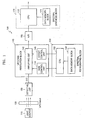
- FIG. 1 illustrates a block diagram of a spectroscopic analyzing apparatus according to an embodiment of the present invention.
- a spectroscopic analyzer 100 includes a light source 110, a specimen 120, a detecting unit 130, an up/down resolution block 140, a spectral region of interest (ROI) weighting block 150, an analog-to-digital (A/D) converter 160, and a spectral synthesis block 170.
- ROI spectral region of interest
- A/D analog-to-digital
- the detecting unit 130 converts an optical signal into an electrical signal. Electrical signals are generally expressed as a variation of voltage, and the voltage variation with respect to time is referred to as a spectrum signal. Since the voltage variation detected by the detecting unit 140 is small, the spectrum signal is modified by the up/down resolution block 140.
- the up/down resolution block 140 includes an amplifying unit 142, a gain control unit 144, and an offset control unit 146.
- the amplifying unit 142 amplifies an output spectrum signal x(n) of the detecting unit 130 and adjusts the size of the amplified signal to be matched with a dynamic active region, i.e., such that the signal can be stably amplified.
- the spectrum signal amplified by the amplifying unit 142 can be divided by a time interval depending on time or by a predetermined time interval.
- the spectra obtained by dividing the spectrum into time intervals can be amplified by the amplifying unit 142 by different values, i.e., by a gain value and an offset value that are control signals provided by the gain control unit 144 and the offset control unit 146.
- the control signals of the gain control unit 144 and the offset control unit 146 are provided from the spectral ROI weighting block 150.
- the spectral ROI weighting block 150 includes a CPU 152 and a data memory block 154.
- the data memory block 154 stores gain and offset values relative to positions in the waveform, which are read by the CPU 152 and output to the respective gain control unit 144 and the offset control unit 146.
- the spectral ROI weighting block 150 selects a spectral wavelength band to be used for the analysis of the specimen on the spectrum of the specimen 120 and divides the spectrum depending on time according to the selected wavelength band.
- the spectral portion having increased resolution is determined by a weighting vector generated in the spectral ROI weighting block 150. This weighting vector is provided to the gain control unit 144 and the offset control unit 146.
- the A/D converter 160 quantizes the amplified spectrum to convert it into a digital signal and transfers the quantized digital signal to the spectral synthesis block 170.
- the spectral synthesis block 170 includes a CPU 172 and a data memory block 174. The position in the waveform at which different amplification parameters are to be used remains the same for the reverse conversion performed by the spectral synthesis block 170. This position, as well as the reverse conversion information for the gain and offset values, is stored in the data memory block 174.
- the spectral synthesis block 170 synthesizes the spectrum having a resolution applied differentially depending on a time interval in the up/down resolution block 140 to an original shaped spectrum.
- the functions of the spectral ROI weighting block 150 and the spectral synthesis block 170 may be performed by the same CPU and data memory block.
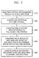
- a spectral portion to receive enhanced resolution is selected in step 210.
- the original spectrum x(n) is divided by a time interval at step 220.
- a weighting vector W is constructed with reference to the divided time interval at step 230.
- a vector R which varies the gain and offset of the x(n) spectrum depending on the weighting vector W and the time interval is constructed at step 240. For example, the offset adjustment may be selected to ensure that an amplified spectrum remains within the dynamic active region.
- a vector S for restoring the divided spectrum to the original size spectrum is constructed at step 250.
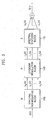
- the spectral ROI weighting block 150 multiplies the weighting vector W with the original spectrum x(n) received from the detecting unit (see 130 of FIG. 1 ) to thereby generate an ROI vector v (n).
- v n v 0 n v 1 n v 2 n . . . v k n
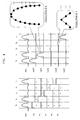
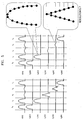
- FIG. 4 illustrates the weighting vector W and the ROI vector v (n) with respect to the original spectrum x(n). While the resolution of the second ROI vector v 1 (n) allows eight gradations to be determined, the resolution of the fourth ROI vector v 3 (n) only allows three gradations to be determined. This discrepancy arises because a peak of the fourth ROI vector v 3 (n) is smaller than that of the second ROI vector v 1 (n).
- the up/down resolution block 140 receives the ROI vector v (n) and generates a resolution vector r(n) by performing a predetermined functional product of the received ROI vector v (n) and the gain and offset vector R having a gain component H and an offset component G.
- the functional product of the resolution vector r(n) and the synthesis vector S for restoring a quantized vector to the size of the original vector x(n) is performed to generate a restoring vector z(n).
- a restored spectrum x(n) including a spectral portion with enhanced resolution is obtained by combining the spectral portions of z(n), as indicated in FIG. 3 .
- the restored spectrum again has amplitudes and shapes, i.e., form, of the original spectrum x(n).
- FIG. 5 shows the resolution vector r(n) and the restoring vector z (n) with respect to the original spectrum x(n).
- the resolution of the fourth ROI vector v 3 (n) which only allowed three gradations in FIG. 4 , is enhanced to allow seven gradations.
- a method for enhancing the resolution of the spectrum by a time interval using the spectroscopic analyzer 100 can be summarized as shown in FIG. 6 .
- Light from the light source 110 is projected onto the specimen 120 at step 610.
- Light from the specimen 120 is detected by the detecting unit 130 at step 620, which outputs a spectrum.
- the spectrum is temporally divided into a plurality of spectra at step 630 in accordance with the weighting vector W.
- the gain and offset of each spectra is adjusted in the up/down resolution block 140 in accordance with the gain and offset vector R and the weighting vector W in step 630 to form a resolution vector, with a resolution component for each spectra.
- the resolution vector is quantized by the A/D converter 160 at step 640.
- the quantized spectra, having an enhanced resolution are synthesized to form restoring spectra having enhanced resolution and the original form at step 650.
- the enhanced resolution of the restored spectra is maintained.
- the resolution enhanced spectrum is formed by combining the restored spectra at step 660.
Landscapes
- Physics & Mathematics (AREA)
- Spectroscopy & Molecular Physics (AREA)
- General Physics & Mathematics (AREA)
- Biochemistry (AREA)
- Chemical & Material Sciences (AREA)
- Analytical Chemistry (AREA)
- Life Sciences & Earth Sciences (AREA)
- General Health & Medical Sciences (AREA)
- Health & Medical Sciences (AREA)
- Immunology (AREA)
- Pathology (AREA)
- Spectrometry And Color Measurement (AREA)
- Investigating Or Analysing Materials By Optical Means (AREA)
Claims (16)
- Procédé d'analyse d'un composant spectroscopique, le procédé comprenant :la projection (610) de lumière sur un échantillon (110) ;la détection (620) d'un spectre optique à partir de l'échantillon, où le spectre optique est généré comme signal du spectre de sortie sous forme d'un signal électrique présentant une variation de tension en fonction du temps ;la génération d'un vecteur de zone d'intérêt, ZI, par division temporelle du signal du spectre de sortie en une pluralité d'intervalles de temps et en construisant un vecteur de pondération en référence à l'intervalle de temps divisé, et en multipliant le vecteur de pondération par le signal du spectre de sortie ;la génération d'un vecteur de résolution exprimé par r(n) = F[R, v(n)] = H •v(n) + G; où v(n) est le vecteur ZI et r(n) est le vecteur de résolution, à l'aide d'un vecteur de gain et de décalage R exprimé par
 la quantification (640) du vecteur de résolution pour obtenir un signal numérique ; etl'application (650) d'un vecteur de synthèse des spectres quantifiés pour redonner à chaque spectre quantifié une forme d'origine d'un spectre d'origine correspondant.
 - Procédé selon la revendication 1, où le vecteur de pondération choisit une zone d'intérêt spectrale ZI pour augmenter la résolution dans le spectre de la pluralité des spectres obtenus en divisant en fonction de la zone d'intérêt.
- Procédé selon la revendication 2, où le vecteur de gain et de décalage définit le gain et le décalage pour le spectre correspondant de la zone d'intérêt ZI pour que l'étape d'application du vecteur de gain et de décalage règle une amplitude de crête du spectre correspondant dans une région active dynamique.
- Procédé selon une quelconque des revendications précédentes, où le vecteur de synthèse S est exprimé par

- Procédé selon une quelconque des revendications précédentes, où le vecteur de pondération est exprimé par

- Procédé d'analyse d'un composant spectroscopique selon la revendication 1, le procédé comprenant :la génération du vecteur de gain et de décalage pour l'amplification d'une forme d'origine de chaque spectre de la zone d'intérêt ;la génération du vecteur de synthèse pour redonner leur forme d'origine aux spectres divisés ;la multiplication du vecteur de pondération par le spectre optique pour générer un vecteur de ZI;la multiplication du vecteur de gain et de décalage par le vecteur ZI pour générer un vecteur de résolution ;la multiplication du vecteur de résolution par le spectre de synthèse optique pour générer un vecteur de restauration ; etl'addition des vecteurs de restauration pour obtenir un spectre de la forme d'origine de résolution améliorée.
- Procédé selon la revendication 6, où le vecteur de gain et de décalage amplifie le spectre correspondant de la zone d'intérêt pour régler une amplitude de crête du spectre correspondant dans une région active dynamique.
- Procédé selon la revendication 6 ou la revendication 7, où le vecteur de pondération est exprimé par

- Procédé selon l'une des revendications 6, 7 ou 8, où le vecteur de résolution est exprimé par r(n) = F[R,v(n)] = H •v(n) + G, dans lequel le vecteur de gain et de décalage R est exprimé par

- Procédé selon l'une des revendications 6, 7 ou 8, où le vecteur de synthèse S est exprimé par

- Analyseur spectroscopique, comprenant:une source de lumière (110) ;un détecteur (130) qui est disposé pour détecter un spectre optique généré par la projection de lumière depuis la source lumineuse sur l'échantillon et pour générer un signal du spectre de sortie sous forme d'un signal électrique ayant une variation de tension en fonction du temps ;caractérisé en ce que l'analyseur spectroscopique comprendun bloc de pondération spectral (150) qui est disposé pour générer un vecteur de zone d'intérêt, ZI, par division temporelle du signal du spectre de sortie pour constituer une pluralité de spectres correspondant à une pluralité d'intervalles de temps et en construisant un vecteur de pondération en référence à l'intervalle de temps divisé, et en multipliant le vecteur de pondération par la signal du spectre de sortie ;un bloc de résolution de haut en bas (140) qui est disposé pour appliquer un vecteur de gain et de décalage pour multiplier un gain et ajouter un décalage à chaque spectre parmi la pluralité des spectres, et générer un vecteur de résolution avec une valeur de résolution de chaque spectre parmi la pluralité de spectres, où le vecteur de résolution est exprimé par r(n) = F[R,v(n)] = H •v(n) + G, dans lequel v(n) est le vecteur ZI et r(n) est le vecteur de résolution, et le vecteur de gain et de décalage R est exprimé par
 un convertisseur analogique-numérique (160) qui est disposé pour recevoir la sortie du vecteur de résolution depuis le bloc de résolution de haut en bas, et convertit le vecteur de résolution reçu en un signal numérique ; etun bloc de synthèse du spectre (170) qui est disposé pour multiplier une sortie du convertisseur analogique-numérique par un vecteur de synthèse pour redonner au spectre optique une forme d'origine afin de générer un vecteur de restauration et d'ajouter le vecteur de restauration à la sortie du convertisseur analogique-numérique pour générer un spectre présentant la forme d'origine et une résolution améliorée.
 - Analyseur spectroscopique selon la revendication 11, où le vecteur de pondération choisit une zone d'amplitude relativement faible, et, ainsi, une résolution relativement basse, dans les spectres optiques divisés par un intervalle de temps prédéterminé comme ZI.
- Analyseur spectroscopique selon la revendication 11 ou la revendication 12, où le vecteur de gain et de décalage définit des valeurs de gain et de décalage pour amplifier le spectre correspondant de la zone d'intérêt pour régler une amplitude de crête du spectre correspondant dans une région active dynamique.
- Analyseur spectroscopique selon les revendications 11, 12 ou 13, où le bloc de résolution de haut en bas comprend :une unité de contrôle de gain (144) qui reçoit le vecteur de gain en provenance du bloc de pondération spectrale ;une unité de contrôle de décalage (146) qui reçoit le vecteur de décalage en provenance du bloc de pondération spectrale ; etune unité d'amplification (142) qui amplifie le spectre de la ZI conformément au vecteur de gain vecteur et au vecteur de décalage.
- Analyseur spectroscopique selon une quelconque des revendications 11 à 14, où le vecteur de pondération est exprimé par

- Analyseur spectroscopique selon une quelconque des revendications 11 à 15, où le vecteur de synthèse S est exprimé par

Applications Claiming Priority (2)
| Application Number | Priority Date | Filing Date | Title |
|---|---|---|---|
| KR2003085825 | 2003-11-28 | ||
| KR20030085825A KR100571825B1 (ko) | 2003-11-28 | 2003-11-28 | 가변형 스펙트럼의 분해능 향상을 위한 분광 성분 분석방법 및 그 장치 |
Publications (3)
| Publication Number | Publication Date |
|---|---|
| EP1536221A2 EP1536221A2 (fr) | 2005-06-01 |
| EP1536221A3 EP1536221A3 (fr) | 2006-04-19 |
| EP1536221B1 true EP1536221B1 (fr) | 2016-09-21 |
Family
ID=34464772
Family Applications (1)
| Application Number | Title | Priority Date | Filing Date |
|---|---|---|---|
| EP04257269.3A Expired - Lifetime EP1536221B1 (fr) | 2003-11-28 | 2004-11-24 | Appareil optique et procédé d'amélioration de la résolution de spectres de fréquence à variation temporelle |
Country Status (4)
| Country | Link |
|---|---|
| US (1) | US7245372B2 (fr) |
| EP (1) | EP1536221B1 (fr) |
| JP (1) | JP2005164589A (fr) |
| KR (1) | KR100571825B1 (fr) |
Families Citing this family (19)
| Publication number | Priority date | Publication date | Assignee | Title |
|---|---|---|---|---|
| KR100763602B1 (ko) * | 2006-03-16 | 2007-10-04 | 엘에스산전 주식회사 | 디지털 데이터 분해능 조절 방법 |
| WO2013065035A1 (fr) | 2011-11-03 | 2013-05-10 | Verifood Ltd. | Système de spectrométrie à faible coût pour analyse d'aliments d'utilisateur final |
| CN105593651B (zh) | 2013-08-02 | 2019-06-07 | 威利食品有限公司 | 光谱测定系统和方法、光谱设备和系统 |
| CN106461461A (zh) | 2014-01-03 | 2017-02-22 | 威利食品有限公司 | 光谱测定系统、方法和应用 |
| CN107250739A (zh) | 2014-10-23 | 2017-10-13 | 威利食品有限公司 | 手持式光谱仪的附件 |
| WO2016125165A2 (fr) | 2015-02-05 | 2016-08-11 | Verifood, Ltd. | Système de spectrométrie comprenant un faisceau de visée visible |
| WO2016125164A2 (fr) | 2015-02-05 | 2016-08-11 | Verifood, Ltd. | Applications d'un système de spectrométrie |
| WO2016162865A1 (fr) | 2015-04-07 | 2016-10-13 | Verifood, Ltd. | Détecteur pour système de spectrométrie |
| US10066990B2 (en) | 2015-07-09 | 2018-09-04 | Verifood, Ltd. | Spatially variable filter systems and methods |
| US10203246B2 (en) | 2015-11-20 | 2019-02-12 | Verifood, Ltd. | Systems and methods for calibration of a handheld spectrometer |
| US10254215B2 (en) | 2016-04-07 | 2019-04-09 | Verifood, Ltd. | Spectrometry system applications |
| WO2018015951A1 (fr) | 2016-07-20 | 2018-01-25 | Verifood, Ltd. | Accessoires pour spectromètre portatif |
| US10791933B2 (en) | 2016-07-27 | 2020-10-06 | Verifood, Ltd. | Spectrometry systems, methods, and applications |
| CN107643269B (zh) * | 2017-08-31 | 2020-02-04 | 深圳市中达瑞和科技有限公司 | 交叉字迹时序鉴别方法、系统及计算装置 |
| CN108932923B (zh) * | 2018-07-03 | 2020-09-01 | 深圳市华星光电半导体显示技术有限公司 | Amoled的侦测系统及侦测方法 |
| EP3864384A4 (fr) | 2018-10-08 | 2022-06-29 | Verifood Ltd. | Accessoires pour spectromètres optiques |
| CN109724959B (zh) * | 2019-01-17 | 2021-01-22 | 深圳市太赫兹科技创新研究院有限公司 | 一种光谱仪及其控制器 |
| KR102217903B1 (ko) * | 2019-11-19 | 2021-02-19 | 엘아이지넥스원 주식회사 | 신호 계측 회로를 이용한 신호 계측 장치 및 방법 |
| JP7531892B2 (ja) * | 2020-11-18 | 2024-08-13 | 日本分光株式会社 | スペクトルの相違を数値化することに適したスペクトル測定装置 |
Family Cites Families (11)
| Publication number | Priority date | Publication date | Assignee | Title |
|---|---|---|---|---|
| US3708227A (en) * | 1971-04-19 | 1973-01-02 | Optical Coating Laboratory Inc | Spectral analysis instrument with programmed spectral slit width |
| US3828173A (en) * | 1972-08-01 | 1974-08-06 | Dickey John Corp | Grain analysis computer circuit |
| US4037970A (en) * | 1972-08-24 | 1977-07-26 | Neotec Corporation | Optical analyzer for agricultural products |
| US4260262A (en) * | 1978-11-28 | 1981-04-07 | Neotec Corporation | Grain quality analyzer |
| US4648051A (en) * | 1984-10-15 | 1987-03-03 | The Board Of Trustees Of The Leland Stanford Junior University | Color imaging process |
| JPS61269463A (ja) | 1985-05-23 | 1986-11-28 | Hitachi Medical Corp | 画像読取装置 |
| US5194865A (en) * | 1991-12-06 | 1993-03-16 | Interbold | Analog-to-digital converter circuit having automatic range control |
| US5784158A (en) * | 1995-11-22 | 1998-07-21 | Lastek Laboratories Pty. Ltd. | Broad spectrum spectrometer apparatus |
| JP4061765B2 (ja) * | 1999-02-09 | 2008-03-19 | コニカミノルタセンシング株式会社 | 蛍光試料の分光特性測定装置及びその測定方法 |
| US6615162B2 (en) * | 1999-12-06 | 2003-09-02 | Dmi Biosciences, Inc. | Noise reducing/resolution enhancing signal processing method and system |
| JP4459390B2 (ja) * | 2000-06-08 | 2010-04-28 | 浜松ホトニクス株式会社 | 蛍光測定方法、蛍光測定装置及びそれを用いた試料評価装置 |
-
2003
- 2003-11-28 KR KR20030085825A patent/KR100571825B1/ko not_active Expired - Fee Related
-
2004
- 2004-11-08 US US10/982,814 patent/US7245372B2/en not_active Expired - Lifetime
- 2004-11-24 EP EP04257269.3A patent/EP1536221B1/fr not_active Expired - Lifetime
- 2004-11-25 JP JP2004340993A patent/JP2005164589A/ja active Pending
Also Published As
| Publication number | Publication date |
|---|---|
| US20050117151A1 (en) | 2005-06-02 |
| EP1536221A3 (fr) | 2006-04-19 |
| US7245372B2 (en) | 2007-07-17 |
| EP1536221A2 (fr) | 2005-06-01 |
| JP2005164589A (ja) | 2005-06-23 |
| KR20050052654A (ko) | 2005-06-03 |
| KR100571825B1 (ko) | 2006-04-17 |
Similar Documents
| Publication | Publication Date | Title |
|---|---|---|
| EP1536221B1 (fr) | Appareil optique et procédé d'amélioration de la résolution de spectres de fréquence à variation temporelle | |
| US6040914A (en) | Simple, low cost, laser absorption sensor system | |
| EP0647837B1 (fr) | Analyseur d'un spectre optique et procédé | |
| US20040130725A1 (en) | Propagation measuring apparatus and a propagation measuring method | |
| KR100354852B1 (ko) | 정보획득방법 | |
| JP2001525931A (ja) | 光スペクトル測定用装置とその方法 | |
| EP0420135B1 (fr) | Appareil spectrophotométrique à correction des distorsions de la balayage rapide | |
| EP0517800B1 (fr) | Procede de reference spectral ''en ligne'' pour spectrometres | |
| Kuehl et al. | Dual-beam Fourier transform infrared spectrometer | |
| CN1300574C (zh) | 确定材料中水分的设备和分析方法 | |
| CN114755194A (zh) | 一种糖化血红蛋白检测器及其信号产生和处理方法 | |
| US9746374B2 (en) | Spectrophotometer and spectrophotometric measurement method | |
| US20020121890A1 (en) | Multiple simultaneous optical frequency measurement | |
| EP1645854B1 (fr) | Dispositif et procédé pour mesurer la linéarité d'un détecteur optique | |
| US6147762A (en) | Method of spectroscopic investigation of electromagnetic radiation by means of a fourier spectrometer | |
| EP1376099B1 (fr) | Appareil et méthode de mesure du dichroisme circulaire dans l'infrarouge | |
| JP2006284586A (ja) | 電界差分処理によるコモンモード抑圧を具えた電力比決定システムおよび方法 | |
| CN113295655B (zh) | 一种大动态范围光谱透射率测量装置及其标定与测量方法 | |
| JP3095970B2 (ja) | デコンボリューション処理方法及び装置 | |
| CN116202621B (zh) | 射频标记光谱仪及光谱测量方法 | |
| Guilloteau et al. | Imaging at the IRAM plateau de Bure interferometer | |
| JPH1048047A (ja) | インターフェログラムの測定方法 | |
| JP2818043B2 (ja) | パルス光源を用いたフーリエ変換分光法 | |
| JP2004045348A (ja) | インターフェログラムの処理回路および処理方法 | |
| JP3431777B2 (ja) | 粒度分布測定装置 |
Legal Events
| Date | Code | Title | Description |
|---|---|---|---|
| PUAI | Public reference made under article 153(3) epc to a published international application that has entered the european phase |
Free format text: ORIGINAL CODE: 0009012 |
|
| 17P | Request for examination filed |
Effective date: 20041208 |
|
| AK | Designated contracting states |
Kind code of ref document: A2 Designated state(s): AT BE BG CH CY CZ DE DK EE ES FI FR GB GR HU IE IS IT LI LU MC NL PL PT RO SE SI SK TR |
|
| AX | Request for extension of the european patent |
Extension state: AL HR LT LV MK YU |
|
| PUAL | Search report despatched |
Free format text: ORIGINAL CODE: 0009013 |
|
| AK | Designated contracting states |
Kind code of ref document: A3 Designated state(s): AT BE BG CH CY CZ DE DK EE ES FI FR GB GR HU IE IS IT LI LU MC NL PL PT RO SE SI SK TR |
|
| AX | Request for extension of the european patent |
Extension state: AL HR LT LV MK YU |
|
| AKX | Designation fees paid |
Designated state(s): DE FR GB |
|
| 17Q | First examination report despatched |
Effective date: 20101004 |
|
| RAP1 | Party data changed (applicant data changed or rights of an application transferred) |
Owner name: SAMSUNG ELECTRONICS CO., LTD. |
|
| GRAP | Despatch of communication of intention to grant a patent |
Free format text: ORIGINAL CODE: EPIDOSNIGR1 |
|
| INTG | Intention to grant announced |
Effective date: 20160401 |
|
| GRAS | Grant fee paid |
Free format text: ORIGINAL CODE: EPIDOSNIGR3 |
|
| GRAA | (expected) grant |
Free format text: ORIGINAL CODE: 0009210 |
|
| AK | Designated contracting states |
Kind code of ref document: B1 Designated state(s): DE FR GB |
|
| REG | Reference to a national code |
Ref country code: GB Ref legal event code: FG4D |
|
| REG | Reference to a national code |
Ref country code: DE Ref legal event code: R096 Ref document number: 602004049973 Country of ref document: DE |
|
| REG | Reference to a national code |
Ref country code: FR Ref legal event code: PLFP Year of fee payment: 13 |
|
| REG | Reference to a national code |
Ref country code: DE Ref legal event code: R097 Ref document number: 602004049973 Country of ref document: DE |
|
| PLBE | No opposition filed within time limit |
Free format text: ORIGINAL CODE: 0009261 |
|
| STAA | Information on the status of an ep patent application or granted ep patent |
Free format text: STATUS: NO OPPOSITION FILED WITHIN TIME LIMIT |
|
| 26N | No opposition filed |
Effective date: 20170622 |
|
| REG | Reference to a national code |
Ref country code: FR Ref legal event code: PLFP Year of fee payment: 14 |
|
| REG | Reference to a national code |
Ref country code: FR Ref legal event code: PLFP Year of fee payment: 15 |
|
| PGFP | Annual fee paid to national office [announced via postgrant information from national office to epo] |
Ref country code: FR Payment date: 20201023 Year of fee payment: 17 Ref country code: GB Payment date: 20201023 Year of fee payment: 17 Ref country code: DE Payment date: 20201020 Year of fee payment: 17 |
|
| REG | Reference to a national code |
Ref country code: DE Ref legal event code: R119 Ref document number: 602004049973 Country of ref document: DE |
|
| GBPC | Gb: european patent ceased through non-payment of renewal fee |
Effective date: 20211124 |
|
| PG25 | Lapsed in a contracting state [announced via postgrant information from national office to epo] |
Ref country code: GB Free format text: LAPSE BECAUSE OF NON-PAYMENT OF DUE FEES Effective date: 20211124 Ref country code: DE Free format text: LAPSE BECAUSE OF NON-PAYMENT OF DUE FEES Effective date: 20220601 |
|
| PG25 | Lapsed in a contracting state [announced via postgrant information from national office to epo] |
Ref country code: FR Free format text: LAPSE BECAUSE OF NON-PAYMENT OF DUE FEES Effective date: 20211130 |