EP1536263B1 - Lentille de projection grand-angulaire à grande ouverture - Google Patents
Lentille de projection grand-angulaire à grande ouverture Download PDFInfo
- Publication number
- EP1536263B1 EP1536263B1 EP04022369A EP04022369A EP1536263B1 EP 1536263 B1 EP1536263 B1 EP 1536263B1 EP 04022369 A EP04022369 A EP 04022369A EP 04022369 A EP04022369 A EP 04022369A EP 1536263 B1 EP1536263 B1 EP 1536263B1
- Authority
- EP
- European Patent Office
- Prior art keywords
- lens
- projection
- projection lens
- focal length
- positive
- Prior art date
- Legal status (The legal status is an assumption and is not a legal conclusion. Google has not performed a legal analysis and makes no representation as to the accuracy of the status listed.)
- Expired - Lifetime
Links
- 230000003287 optical effect Effects 0.000 claims description 23
- 210000001747 pupil Anatomy 0.000 claims description 14
- 239000000463 material Substances 0.000 claims description 3
- 238000013461 design Methods 0.000 claims description 2
- 241000219739 Lens Species 0.000 description 216
- 240000004322 Lens culinaris Species 0.000 description 23
- 238000005286 illumination Methods 0.000 description 13
- 238000009434 installation Methods 0.000 description 11
- 230000005540 biological transmission Effects 0.000 description 7
- 230000005499 meniscus Effects 0.000 description 6
- 230000004075 alteration Effects 0.000 description 5
- TZCXTZWJZNENPQ-UHFFFAOYSA-L barium sulfate Chemical compound [Ba+2].[O-]S([O-])(=O)=O TZCXTZWJZNENPQ-UHFFFAOYSA-L 0.000 description 5
- 238000005520 cutting process Methods 0.000 description 4
- 238000011161 development Methods 0.000 description 4
- 230000018109 developmental process Effects 0.000 description 4
- 239000006185 dispersion Substances 0.000 description 4
- 230000008901 benefit Effects 0.000 description 3
- 238000012937 correction Methods 0.000 description 3
- 238000004519 manufacturing process Methods 0.000 description 3
- 238000010276 construction Methods 0.000 description 2
- 238000003384 imaging method Methods 0.000 description 2
- 238000012546 transfer Methods 0.000 description 2
- 239000011230 binding agent Substances 0.000 description 1
- 239000011248 coating agent Substances 0.000 description 1
- 238000000576 coating method Methods 0.000 description 1
- 230000007423 decrease Effects 0.000 description 1
- 230000000694 effects Effects 0.000 description 1
- 238000005516 engineering process Methods 0.000 description 1
- 230000006872 improvement Effects 0.000 description 1
- 238000007689 inspection Methods 0.000 description 1
- 238000005457 optimization Methods 0.000 description 1
- 230000002093 peripheral effect Effects 0.000 description 1
- 239000004033 plastic Substances 0.000 description 1
- 229920003023 plastic Polymers 0.000 description 1
- 230000035945 sensitivity Effects 0.000 description 1
- 238000003860 storage Methods 0.000 description 1
- 238000012360 testing method Methods 0.000 description 1
- 238000004804 winding Methods 0.000 description 1
Images



Classifications
-
- G—PHYSICS
- G02—OPTICS
- G02B—OPTICAL ELEMENTS, SYSTEMS OR APPARATUS
- G02B13/00—Optical objectives specially designed for the purposes specified below
- G02B13/02—Telephoto objectives, i.e. systems of the type + - in which the distance from the front vertex to the image plane is less than the equivalent focal length
-
- G—PHYSICS
- G02—OPTICS
- G02B—OPTICAL ELEMENTS, SYSTEMS OR APPARATUS
- G02B9/00—Optical objectives characterised both by the number of the components and their arrangements according to their sign, i.e. + or -
- G02B9/64—Optical objectives characterised both by the number of the components and their arrangements according to their sign, i.e. + or - having more than six components
Definitions
- the invention relates to a high-aperture projection lens with focal lengths shorter than 50 mm.
- the main field of application of the invention is the 35 mm cinema projection.
- Projection objectives for the projection of cinema images must meet a number of technical constraints that affect the selection and arrangement of the optical elements.
- installation conditions relate, for example, to the spatial limitations of the space available for the projection objective given by commercial cinema projectors.
- the diameters of the optical elements used, the housing of the projection lens and the focal distance, ie the distance of the last lens surface from the film plane, must satisfy the installation conditions.
- projection lenses For small cinemas with large screens or for rear projection usually wide-angle projection lenses are required. In many cases, the total focal length of the projection lens is shorter than the specified by the installation conditions kerf. Such projection lenses are referred to as retrofocus projection lenses.
- the entrance pupil D EP is here defined as the opening of the projection lens that a viewer perceives from the direction of the film. As a rule, this is the image of a diaphragm within the projection lens. A large opening D EP thus causes a small f-number k and vice versa.
- the light source used for the projection also has a specific f-number k SP .
- a parabolic or spherical mirror with focal length f SP and edge diameter D SP is used for the illumination, it is possible to calculate a f-number k SP of the mirror from the ratio of these two quantities.
- the f-number of the projection lens is adjusted to the f-number of the mirror to reduce light losses in the projection lens (too small opening) or insufficient illumination (too large opening) to avoid.
- EP 1 134 606 B1 is a projection lens described, which is composed of at least seven on both sides of air adjacent lenses.
- the projection objective has a f-number of 1.9 and is characterized by an arrangement of lenses whose first lens viewed from the image side is designed as a positive lens.
- a bright wide-angle lens with large image-side cut which is composed of at least seven, but usually nine or ten on both sides of adjacent air lenses.
- the wide-angle objective is characterized by an arrangement of lenses whose first lens viewed from the image side is designed as a negative meniscus lens, a second lens as a positive meniscus lens and a third lens as a negative meniscus lens.
- the projection lens is designed as a lightweight retrofocus projection lens. This is achieved by the first two lenses, which have an overall negative focal length. Furthermore, the smallest f-number k min of the projection lens must be 1.8 or less (ie, k min ⁇ 1.8).
- the entrance pupil is defined as the opening of the projection lens, which perceives a fictitious, film-side positioned observer.
- the projected image is optimally illuminated even in its peripheral areas.
- the entrance pupil is arranged closer than at a distance of 100 mm, a bundle of rays emanating from an outer pixel on the same side of the optical axis as the pixel on its side remote from the optical axis is cut by the entrance pupil. Thereby light losses occur.
- the entrance pupil is arranged at a distance of more than 300 mm, the same beam on the side of the optical axis opposite to the pixel is truncated on its side remote from the optical axis by the entrance pupil.
- the projection objective has a diaphragm, in particular a variable diaphragm, between the second positive lens and the third biconvex lens.
- a diaphragm in particular a variable diaphragm, between the second positive lens and the third biconvex lens.
- the diaphragm is arranged at a position at which all beams originating from the binder have a symmetrical cross-section with respect to the optical axis. This ensures that no additional edge effects and shadowing (vignetting) occur through the aperture.
- an aspheric surface is used to correct aberrations, then it makes sense to arrange the aspherical surface on a surface adjacent to the diaphragm. Then, the aspherical surface allows optimal correction of the spherical aberrations at high f-number of the projection lens.
- optical elements typically consist of the lenses customary for the construction of projection objectives or plastics, which are selected with regard to their refractive index and their dispersion properties.
- the proposed projection lens has the advantage that it is also suitable for projectors with high-open illumination mirrors (eg with a f-number of the mirror k sp of 1.7), since the aperture angle u of the projection lens is adapted to the aperture angle ⁇ of the illumination mirrors can. As a result, the light emanating from the illumination mirror is used optimally. At the same time, the projection lens has a relatively long focal length.
- the described construction of the projection lens can be further improved by a number of optional additional features in its optical properties. These optional additional features are described below.
- the aspherical surface does not deviate by more than 10 ⁇ m from a spherical surface.
- the small deviation of the surface from the spherical shape i. E., Only 4-7 microns
- the optical quality inspection of the surface can be greatly simplified, since a test of the surface with expensive holograms can be omitted.
- a further improvement of the projection objective can be achieved by designing the projection objective in such a way that the following condition is fulfilled between the overall length Sumd, the focal distance S'F 'and the total focal length f' of the projection objective: 2 . 8th ⁇ f ' ⁇ Sumd + S'F' ⁇ 4 . 5 ⁇ f '
- the length Sumd designates the distance between the first canvas-side lens surface and the last film-side lens surface.
- the condition (3) is the result of an optimization between uniform illumination of the image and too long a length.
- Sumd + S'F' ⁇ 2 . 8th ⁇ f ' As a result of insufficient illumination and / or excessive vignetting light losses and thus losses in the light intensity of the projection lens would occur. Furthermore, for too small cutting widths, the distance between the projection lens and the film plane would be less than prescribed by the installation conditions. In the case Sumd + S'F' ⁇ 4 . 5 ⁇ f ' however, too thick and expensive lens systems would have to be used so that the transmission of the entire system and thus the light intensity decreases.
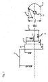
- Fig. 1 Boundary curves of the projection objective housings of two widespread cinema projectors (Ernemann Cine Tec GmbH and Fa. Kinoton GmbH) are shown as examples of typical installation conditions for projection objectives.
- the distance S'F '(in Fig. 1 designated 12) a first lens system with a maximum rim diameter 14 of 40 mm and a total thickness of 8 mm are arranged.
- a second lens system with a maximum rim diameter 16 of 46 mm and a total thickness of 15 mm can be arranged.
- a third lens system can have a maximum edge diameter 17 of 70.65 mm.
- a projection lens is designed so that the lens system meets the installation conditions of both manufacturers.
- the opening angle ⁇ of the cone of light emitted by the light source 18 and reflected by the illumination mirror 19 light illustrates.
- the f-number k SP is the ratio between the focal length f SP (not shown in FIG Fig. 1 ) and the diameter D SP of the mirror.
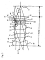
- Fig. 2 shows the basic structure of a projection lens according to a first embodiment. It is about a projection lens with a focal length of 35 mm and a minimum f-number of 1.7.
- the optical axis is designated 34. Between the second positive lens 22 and the third positive lens 24, a shutter 64 is arranged.
- the specified projection lens When the iris is open, the specified projection lens has a f-number of 1.7. So it can also extremely high open illumination mirror with an opening angle up to about 17 ° used as a light source and used efficiently.
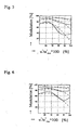
- Fig. 3 shows the resolution of the projection lens according to the first embodiment.
- the field curvature correction must take into account the curvature of the film at the edge in the direction of the projection objective of 0.1 to 0.15 mm caused by the large heat development of the projection lamp.
- the illustrated modulation transfer functions are calculated for such a curved film.
- the resolution was calculated for a color weight corresponding to the mean sensitivity of the human eye.
- Three examples were calculated: the upper two curves belong to the example with a spatial frequency of 20 line pairs per mm (LP / mm), the middle two curves to 40 LP / mm and the lower two curves to 80 LP / mm.
- the solid line shows the resolution of radial line pairs and the dashed line the resolution of tangent line pairs.
- the x-axis indicates the relative deviation from the center of the image to be magnified. On the y-axis, the modulation transfer function is shown at a f-number k of 1.7. The picture was almost infinite.
- the resolution of the projection lens according to the first embodiment corresponds to the resolution of very good projection objectives.
- FIG. 12 shows the relative illuminance of the edges of the enlarged image compared with the center for the projection lens according to the first embodiment.
- FIG. The x-axis corresponds to the x-axis according to Fig. 3 .
- Fig. 8 shows the distortion for the projection lens according to the first embodiment in% of the deviation from the ideal image size.
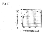
- Fig. 9 is the transmission in% for the projection lens according to Fig. 2 for the wavelength range between 400 nm and 700 nm.
- the cinema projection lens has tolerable losses in the visible wavelength range.
- the cinema projection lens according to the first embodiment has a cutting width S'F 'of 31.898 mm.
- the overall length Sumd of the entire projection lens is 90.647 mm.
- the sum of length and cutting width is thus 122.545 mm and is thus greater than 2.8 f '(98 mm) and less than 4.5 f' (157.5 mm). The above condition (3) is thus satisfied.
- the entrance pupil is located 119.87 mm to the left of the lens surface 62, so that the condition of the position of the entrance pupil is met.
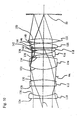
- the aperture 64 facing surface 130 of the lens 112 is again designed as an aspherical surface.
- the aspheric coefficients of this surface 130 are listed in Tab.
- the projection objective specified in the second exemplary embodiment also has a f-number of 1.7, so that once again extremely high-opening illumination mirrors can be used.
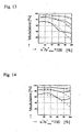
- FIGS. 11 to 14 correspond to the FIGS. 3 to 6 of the first embodiment and show the resolution of the projection lens according to the second embodiment at apertures k of 1.7, 2.0, 2.8 and 4.0.
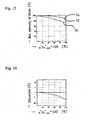
- FIGS. 15 to 17 according to the FIGS. 7 to 9 of the first embodiment and in turn show the relative illuminance, the distortion and the transmission of the cinema projection lens according to the second embodiment.
- the cinema projection lens according to the second embodiment has a focal length S'F '12 of 40.002 mm and a length Sumd of 101.943 mm.
- the total of cut and length is thus 141.945 mm and is thus greater than 2.8f '(133 mm) and less than 4.5f' (213.75 mm).
- the entrance pupil is located 233.521 mm to the left of the last lens surface 150, so that the condition of the position of the entrance pupil is also met by the projection objective according to the second embodiment.
- Tab. 1 numeral Radius / mm Thickness or distance / mm Free diameter / mm Refractive index (n d ) at 588 nm Dispersion ( ⁇ d ) at 588 nm 36 76.068 36.100 20 10.521 1.51680 64.14 38 21.464 26,800 13.354 40 -126.324 24,500 22 13.711 1.72916 54.65 42 -52,802 * 26,600 5,000 64 (Cover) 6,089 44 29.103 29,000 24 16.346 1.64050 60.15 46 -51.643 27,200 4,476 48 -29.981 24,800 26 1,800 1.59270 35,30 50 26.691 24,800 4,000 52 -153.321 24,800 32 1,800 1.80809 22,75 54 63.875 26,400 1,650 56 169.672 27,500 30 4,800
Landscapes
- Physics & Mathematics (AREA)
- General Physics & Mathematics (AREA)
- Optics & Photonics (AREA)
- Lenses (AREA)
Claims (4)
- Lentille de projection, qui convient pour projeter un film sur un écran de projection et qui se compose des éléments suivants, considérés dans l'ordre indiqué à partir de l'écran de projection:- une première lentille négative (20; 110);- une deuxième lentille positive (22; 112);- dans laquelle les deux premières lentilles présentent au total une distance focale négative pour réaliser la lentille de projection sous la forme d'une lentille de projection rétrofocus,- une troisième lentille biconvexe (24; 114);- un diaphragme (64) entre la deuxième lentille positive (22; 112) et la troisième lentille biconvexe (24; 114);- dans laquelle la surface (42; 130) de la deuxième lentille positive (22; 112) tournée vers la troisième lentille biconvexe (24; 114) est formée par une surface asphérique;- une quatrième lentille biconcave (26; 116);- une cinquième lentille biconcave (28; 118);- une sixième lentille biconvexe (30; 120);- une septième lentille biconvexe (32; 122); et- dans laquelle la distance focale totale f' de la lentille de projection remplit la condition
 - dans laquelle la plus petite valeur de diaphragme k de la lentille de projection est égale ou inférieure à 1,8;- dans laquelle la lentille de projection présente une pupille d'entrée pour un observateur fictif, positionné du côté du film;- dans laquelle la pupille d'entrée est disposée à une distance comprise entre 100 mm et 300 mm, du côté de l'écran de projection, à partir de la surface de lentille (62; 150) de la lentille de projection disposée le plus loin du côté du film; et- dans laquelle la lentille de projection est réalisée, dans ses dimensions spatiales, de telle manière qu'elle puisse être montée pour le fonctionnement dans un espace présentant les dimensions suivantes:- l'espace présente la symétrie de révolution autour de l'axe optique;- il commence dans un premier plan (13), qui est perpendiculaire à l'axe optique et qui est disposé à une distance de 30 mm du plan du film (10);- du côté de l'écran de projection, il se raccorde au premier plan (13) un premier volume cylindrique avec un diamètre de 40 mm et une hauteur de 8 mm;- au premier volume cylindrique succède, du côté de l'écran de projection, un deuxième volume cylindrique avec un diamètre de 46 mm et une hauteur de 15 mm; et- au deuxième volume cylindrique succède, du côté de l'écran de projection, un troisième volume cylindrique avec un diamètre de 70,65 mm.
 - Lentille de projection selon la revendication précédente, dans laquelle la surface asphérique (42; 130) ne s'écarte pas de plus de 10 µm d'une surface sphérique.
- Lentille de projection selon l'une quelconque des revendications précédentes, caractérisée en ce qu'elle est réalisée de telle manière qu'elle respecte la condition suivante liant la longueur de construction Sumd, la distance focale frontale S'F' (12) et la distance focale totale f' de la lentille de projection:

- Série de lentilles de projection selon l'une quelconque des revendications précédentes avec des distances focales f' différentes, caractérisée en ce qu'au moins 2 lentilles de projection à distance focale différente comprennent au moins une lentille, qui coïncide avec la surface asphérique en ce qui concerne- le matériau- l'épaisseur- les rayons de courbure et/ou la forme.
Applications Claiming Priority (2)
| Application Number | Priority Date | Filing Date | Title |
|---|---|---|---|
| DE10356338 | 2003-11-28 | ||
| DE10356338A DE10356338B4 (de) | 2003-11-28 | 2003-11-28 | Hoch geöffnetes Weitwinkel-Kinoprojektionsobjektiv |
Related Child Applications (1)
| Application Number | Title | Priority Date | Filing Date |
|---|---|---|---|
| EP10000212.0 Division-Into | 2010-01-12 |
Publications (2)
| Publication Number | Publication Date |
|---|---|
| EP1536263A1 EP1536263A1 (fr) | 2005-06-01 |
| EP1536263B1 true EP1536263B1 (fr) | 2010-07-14 |
Family
ID=34442403
Family Applications (1)
| Application Number | Title | Priority Date | Filing Date |
|---|---|---|---|
| EP04022369A Expired - Lifetime EP1536263B1 (fr) | 2003-11-28 | 2004-09-20 | Lentille de projection grand-angulaire à grande ouverture |
Country Status (4)
| Country | Link |
|---|---|
| US (1) | US7057830B2 (fr) |
| EP (1) | EP1536263B1 (fr) |
| DE (2) | DE10356338B4 (fr) |
| ES (1) | ES2346650T3 (fr) |
Cited By (1)
| Publication number | Priority date | Publication date | Assignee | Title |
|---|---|---|---|---|
| WO2010134951A2 (fr) | 2009-05-21 | 2010-11-25 | Eastman Kodak Company | Projection avec une surface arrondie d'élément de réduction de la granularité |
Families Citing this family (23)
| Publication number | Priority date | Publication date | Assignee | Title |
|---|---|---|---|---|
| JP2010079252A (ja) * | 2008-09-01 | 2010-04-08 | Fujinon Corp | 小型投写レンズおよびこれを用いた投写型表示装置 |
| JP5253126B2 (ja) * | 2008-12-12 | 2013-07-31 | 日東光学株式会社 | レンズシステムおよび表示装置 |
| US7660048B1 (en) * | 2008-12-18 | 2010-02-09 | ZAO “Impulse” | Wide angle lens with large aperture |
| US8172404B2 (en) | 2009-05-21 | 2012-05-08 | Eastman Kodak Company | Projection with lenslet arrangement on speckle reduction element |
| US8366281B2 (en) | 2009-05-21 | 2013-02-05 | Eastman Kodak Company | Out-of-plane motion of speckle reduction element |
| JP5480064B2 (ja) | 2010-08-19 | 2014-04-23 | 富士フイルム株式会社 | 投写用レンズおよび投写型表示装置 |
| JP5801679B2 (ja) * | 2011-10-11 | 2015-10-28 | 日東光学株式会社 | 投射用レンズシステムおよびプロジェクタ装置 |
| US9726859B1 (en) | 2014-03-16 | 2017-08-08 | Navitar Industries, Llc | Optical assembly for a wide field of view camera with low TV distortion |
| US10139595B1 (en) | 2014-03-16 | 2018-11-27 | Navitar Industries, Llc | Optical assembly for a compact wide field of view digital camera with low first lens diameter to image diagonal ratio |
| US9494772B1 (en) | 2014-03-16 | 2016-11-15 | Hyperion Development, LLC | Optical assembly for a wide field of view point action camera with low field curvature |
| US9091843B1 (en) | 2014-03-16 | 2015-07-28 | Hyperion Development, LLC | Optical assembly for a wide field of view point action camera with low track length to focal length ratio |
| US9316808B1 (en) | 2014-03-16 | 2016-04-19 | Hyperion Development, LLC | Optical assembly for a wide field of view point action camera with a low sag aspheric lens element |
| US9316820B1 (en) | 2014-03-16 | 2016-04-19 | Hyperion Development, LLC | Optical assembly for a wide field of view point action camera with low astigmatism |
| US10386604B1 (en) | 2014-03-16 | 2019-08-20 | Navitar Industries, Llc | Compact wide field of view digital camera with stray light impact suppression |
| US9995910B1 (en) | 2014-03-16 | 2018-06-12 | Navitar Industries, Llc | Optical assembly for a compact wide field of view digital camera with high MTF |
| US10545314B1 (en) | 2014-03-16 | 2020-01-28 | Navitar Industries, Llc | Optical assembly for a compact wide field of view digital camera with low lateral chromatic aberration |
| JP6278354B2 (ja) | 2014-04-15 | 2018-02-14 | 株式会社オプトロジック | 撮像レンズ |
| WO2016033743A1 (fr) * | 2014-09-03 | 2016-03-10 | 深圳市大族激光科技股份有限公司 | Objectif photographique |
| KR102279304B1 (ko) * | 2015-10-19 | 2021-07-21 | 삼성전기주식회사 | 촬상 광학계 |
| KR102662849B1 (ko) * | 2016-11-28 | 2024-05-03 | 삼성전기주식회사 | 촬상 광학계 |
| JP6811088B2 (ja) * | 2016-12-26 | 2021-01-13 | 天津欧菲光電有限公司Tianjin Ofilm Opto Electronics Co., Ltd | 撮像レンズおよび撮像装置 |
| RU2649053C1 (ru) * | 2016-12-28 | 2018-03-29 | Публичное акционерное общество "Красногорский завод им. С.А. Зверева" | Широкоугольный светосильный объектив |
| CN116047718A (zh) * | 2023-01-19 | 2023-05-02 | 诚瑞光学(苏州)有限公司 | 摄像光学镜头 |
Family Cites Families (9)
| Publication number | Priority date | Publication date | Assignee | Title |
|---|---|---|---|---|
| DE2436444C2 (de) * | 1974-07-29 | 1982-11-25 | Fa. Carl Zeiss, 7920 Heidenheim | Lichtstarkes photographisches Objektiv mit großem Bildwinkel |
| DD245059A1 (de) | 1985-12-23 | 1987-04-22 | Zeiss Jena Veb Carl | Siebenlinsiges lichtstarkes objektiv mit korrektionsausgleich |
| DE4212067C2 (de) | 1992-04-10 | 1994-02-03 | Isco Optic Gmbh | Weitwinkelobjektiv vom Retrofokustyp |
| JP3559623B2 (ja) * | 1995-07-14 | 2004-09-02 | 富士写真光機株式会社 | 結像レンズ |
| DE50000139D1 (de) * | 2000-01-18 | 2002-05-16 | Isco Optic Gmbh | Projektionsobjektiv |
| JP2001337271A (ja) * | 2000-03-21 | 2001-12-07 | Fuji Photo Optical Co Ltd | 画像読取用レンズおよび画像読取装置 |
| DE50007705D1 (de) | 2000-12-18 | 2004-10-14 | Optische Systeme Goettingen Is | Projektionsobjektiv |
| JP2002341242A (ja) * | 2001-05-21 | 2002-11-27 | Matsushita Electric Ind Co Ltd | 投写レンズとそれを用いたプロジェクター |
| DE10328094B4 (de) * | 2003-06-20 | 2006-04-06 | Jos. Schneider Optische Werke Gmbh | Hoch geöffnetes Projektionsobjektiv |
-
2003
- 2003-11-28 DE DE10356338A patent/DE10356338B4/de not_active Expired - Fee Related
-
2004
- 2004-09-20 DE DE502004011388T patent/DE502004011388D1/de not_active Expired - Lifetime
- 2004-09-20 ES ES04022369T patent/ES2346650T3/es not_active Expired - Lifetime
- 2004-09-20 EP EP04022369A patent/EP1536263B1/fr not_active Expired - Lifetime
- 2004-11-24 US US10/995,484 patent/US7057830B2/en not_active Expired - Fee Related
Cited By (1)
| Publication number | Priority date | Publication date | Assignee | Title |
|---|---|---|---|---|
| WO2010134951A2 (fr) | 2009-05-21 | 2010-11-25 | Eastman Kodak Company | Projection avec une surface arrondie d'élément de réduction de la granularité |
Also Published As
| Publication number | Publication date |
|---|---|
| US20050117225A1 (en) | 2005-06-02 |
| ES2346650T3 (es) | 2010-10-19 |
| DE10356338B4 (de) | 2006-02-23 |
| DE10356338A1 (de) | 2005-07-14 |
| EP1536263A1 (fr) | 2005-06-01 |
| US7057830B2 (en) | 2006-06-06 |
| DE502004011388D1 (de) | 2010-08-26 |
Similar Documents
| Publication | Publication Date | Title |
|---|---|---|
| EP1536263B1 (fr) | Lentille de projection grand-angulaire à grande ouverture | |
| DE102019009255B3 (de) | Optisches System und Bildaufnahmegerät | |
| EP2535751B1 (fr) | Objectif de caméra | |
| DE69222729T2 (de) | Optisches System zur wiederholten Abbildung mit refraktiven und diffraktiven optischen Elementen | |
| DE69618046T2 (de) | Optisches System, Bildbeobachtungsvorrichtung und Bildaufnahmevorrichtung mit Verwendung derselben | |
| DE102010035034B3 (de) | Hoch geöffnetes Weitwinkelobjektiv | |
| DE102016223429A1 (de) | Abbildungsobjektiv und Abbildungsvorrichtung | |
| EP1987386A2 (fr) | Système optique de ciné-projection numérique | |
| DE102016223427A1 (de) | Abbildungsobjektiv und Abbildungsvorrichtung | |
| EP2535752A1 (fr) | Objectif anamorphoseur | |
| DE2739488B2 (de) | Fotografisches Weitwinkelobjektiv | |
| DE4041240C2 (de) | Projektionsobjektiv | |
| DE10328094B4 (de) | Hoch geöffnetes Projektionsobjektiv | |
| DE102016125402B4 (de) | Kompaktes Kameraobjektiv höchster Abbildungsgüte für eine Kamera mit Vollformatsensor, Verwendung eines solchen Kameraobjektivs und Foto- oder Filmkamera mit einem solchen Kameraobjektiv | |
| DE112011102792T5 (de) | Projektionsanzeigeeinrichtung | |
| DE2035424C3 (de) | Afokales Vorsatzsystem für ein Objektiv fester Brennweite | |
| DE60025661T2 (de) | Weitwinkeliges katoptrisches System | |
| DE2842055C2 (de) | Weitwinkelobjektiv vom Typ umgekehrter Teleobjektive | |
| DE102016115474B4 (de) | Abbildungsobjektiv und abbildungsvorrichtung | |
| DE10353563B4 (de) | Projetionsobjektiv für die Projektion digitaler Bilddaten | |
| DE102023107006A1 (de) | Optisches System und Bildaufnahmegerät mit dem optischen System | |
| DE602004001027T2 (de) | Photoobjektiv | |
| DE102018106236B3 (de) | Objektiv mit fester Brennweite | |
| DE102023129066A1 (de) | Zoomobjektiv und bildgebendes gerät mit diesem | |
| DE69421044T2 (de) | Kompaktes optisches Linsensystem |
Legal Events
| Date | Code | Title | Description |
|---|---|---|---|
| PUAI | Public reference made under article 153(3) epc to a published international application that has entered the european phase |
Free format text: ORIGINAL CODE: 0009012 |
|
| AK | Designated contracting states |
Kind code of ref document: A1 Designated state(s): AT BE BG CH CY CZ DE DK EE ES FI FR GB GR HU IE IT LI LU MC NL PL PT RO SE SI SK TR |
|
| AX | Request for extension of the european patent |
Extension state: AL HR LT LV MK |
|
| 17P | Request for examination filed |
Effective date: 20050530 |
|
| AKX | Designation fees paid |
Designated state(s): DE ES FR GB IT |
|
| 17Q | First examination report despatched |
Effective date: 20051019 |
|
| GRAP | Despatch of communication of intention to grant a patent |
Free format text: ORIGINAL CODE: EPIDOSNIGR1 |
|
| GRAS | Grant fee paid |
Free format text: ORIGINAL CODE: EPIDOSNIGR3 |
|
| GRAA | (expected) grant |
Free format text: ORIGINAL CODE: 0009210 |
|
| AK | Designated contracting states |
Kind code of ref document: B1 Designated state(s): DE ES FR GB IT |
|
| REG | Reference to a national code |
Ref country code: GB Ref legal event code: FG4D Free format text: NOT ENGLISH |
|
| REF | Corresponds to: |
Ref document number: 502004011388 Country of ref document: DE Date of ref document: 20100826 Kind code of ref document: P |
|
| REG | Reference to a national code |
Ref country code: ES Ref legal event code: FG2A Ref document number: 2346650 Country of ref document: ES Kind code of ref document: T3 |
|
| PLBE | No opposition filed within time limit |
Free format text: ORIGINAL CODE: 0009261 |
|
| STAA | Information on the status of an ep patent application or granted ep patent |
Free format text: STATUS: NO OPPOSITION FILED WITHIN TIME LIMIT |
|
| 26N | No opposition filed |
Effective date: 20110415 |
|
| REG | Reference to a national code |
Ref country code: DE Ref legal event code: R097 Ref document number: 502004011388 Country of ref document: DE Effective date: 20110415 |
|
| PGFP | Annual fee paid to national office [announced via postgrant information from national office to epo] |
Ref country code: GB Payment date: 20120920 Year of fee payment: 9 |
|
| PGFP | Annual fee paid to national office [announced via postgrant information from national office to epo] |
Ref country code: DE Payment date: 20120927 Year of fee payment: 9 Ref country code: ES Payment date: 20120924 Year of fee payment: 9 Ref country code: IT Payment date: 20120925 Year of fee payment: 9 |
|
| PGFP | Annual fee paid to national office [announced via postgrant information from national office to epo] |
Ref country code: FR Payment date: 20121008 Year of fee payment: 9 |
|
| GBPC | Gb: european patent ceased through non-payment of renewal fee |
Effective date: 20130920 |
|
| REG | Reference to a national code |
Ref country code: DE Ref legal event code: R119 Ref document number: 502004011388 Country of ref document: DE Effective date: 20140401 |
|
| REG | Reference to a national code |
Ref country code: FR Ref legal event code: ST Effective date: 20140530 |
|
| PG25 | Lapsed in a contracting state [announced via postgrant information from national office to epo] |
Ref country code: GB Free format text: LAPSE BECAUSE OF NON-PAYMENT OF DUE FEES Effective date: 20130920 |
|
| PG25 | Lapsed in a contracting state [announced via postgrant information from national office to epo] |
Ref country code: IT Free format text: LAPSE BECAUSE OF NON-PAYMENT OF DUE FEES Effective date: 20130920 Ref country code: FR Free format text: LAPSE BECAUSE OF NON-PAYMENT OF DUE FEES Effective date: 20130930 Ref country code: DE Free format text: LAPSE BECAUSE OF NON-PAYMENT OF DUE FEES Effective date: 20140401 |
|
| REG | Reference to a national code |
Ref country code: ES Ref legal event code: FD2A Effective date: 20150428 |
|
| PG25 | Lapsed in a contracting state [announced via postgrant information from national office to epo] |
Ref country code: ES Free format text: LAPSE BECAUSE OF NON-PAYMENT OF DUE FEES Effective date: 20130921 |